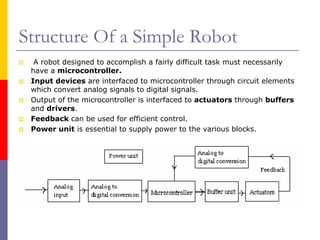
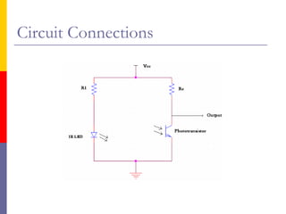
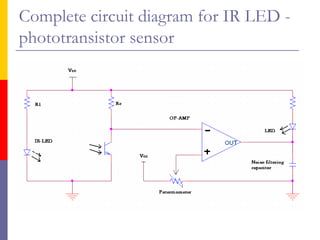
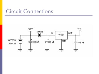
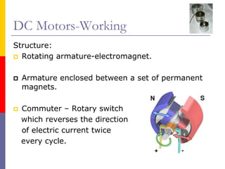
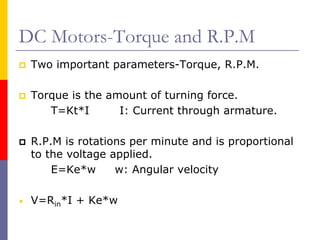
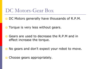
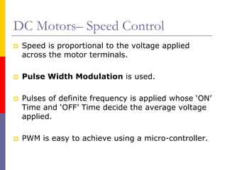
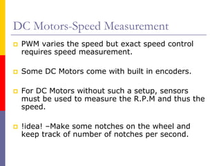
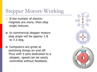
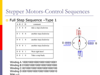
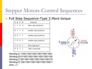
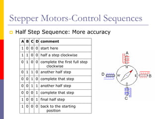
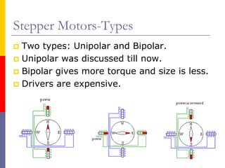
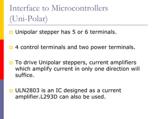
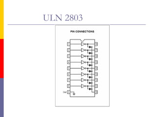
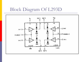
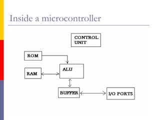
Building Automated
      Robots

       Sagar N
           &
       Sanjay R
      III year ECE
What is an automated robot?
 A machine which can
 accomplish a predefined task
 without external control.

 It must possess sufficient
 intelligence to take decisions.

 It must not receive any kind
 of aid from an external agent.
 It should have an on-board
 power source.

 Micromouse video.
Structure Of a Simple Robot
  A robot designed to accomplish a fairly difficult task must necessarily
 have a microcontroller.
 Input devices are interfaced to microcontroller through circuit elements
 which convert analog signals to digital signals.
 Output of the microcontroller is interfaced to actuators through buffers
 and drivers.
 Feedback can be used for efficient control.
 Power unit is essential to supply power to the various blocks.
A line follower…
 Sensors act as inputs to the microcontroller.
 Sensor outputs are given to the microcontroller after analog
 to digital conversion.
 Microcontroller is the basic intelligence unit which
 processes the input and controls the actuators – motors in
 this case.
 Motor drivers are either current amplifiers or pulse
 sequencers or both. They are used to drive the motors and
 prevent the microcontroller from getting burnt.
 A power supply unit is designed so as to provide proper
 voltage levels to microcontrollers, drivers and motors.
 Stabilized power to the microcontroller is an absolute
 necessity.
Sensors
 A LED is diode which emits light when forward
 biased by sufficient voltage.

 LDR: Its resistance varies with incident light intensity.

 Phototransistor is a transistor in which, the base
 current is proportional to IR Rays and, to a certain extent, visible
 light incident on it.

 IR LED: This emits infrared rays when forward biased.

 Commonly used reflective sensors:
    -LDR and LED pair
    -Phototransistor and IR LED pair
LDR and LED pair
LDR has two terminals similar to a normal resistor but the
resistance varies inversely with the light intensity.

Its response is most significant in the visible region of
spectrum.

White LEDs give better performance as compared to other
types.

A small bulb can be used instead of LED but it consumes
more power and dissipates a lot of heat.

This sensor pair is better suited for light sensing bots and
not for reflective sensing.
Phototransistor and IR LED Pair
 IR LED is similar to normal LED except that it
 emits IR Rays.

 Phototransistor generally has two terminals-
 collector and emitter –base drive is proportional
 to light intensity.

 IR LED emission strength increases by decreasing
 the series resistance and phototransistor
 sensitivity increases by increasing the collector
 resistance.

 Phototransistor response is best for IR radiation.
Spectral distribution of IR LED and
phototransistor sensitivities
Circuit Connections
Interface to microcontroller
 Microcontrollers do not recognize voltages
 other than standard TTL levels.

 Comparators are used to convert the input
 analog signals to digital.

 Op amps LM324 can be used as
 comparators; LM339 is an IC designed as
 a comparator-they can be used for higher
 frequency operations.
Complete circuit diagram for IR LED -
phototransistor sensor
Power Supply to Microcontrollers (µC)
 For proper functioning of µC a constant
 power supply is necessary.

 A Voltage regulator is used to give a
 constant 5V to the microcontroller.

 IC 7805 is generally used as a voltage
 regulator.
Circuit Connections
Motors
 Two types of motors are generally used :
 -DC Motors
 -Stepper Motors

 DC Motors:-Advantages: Small and light, cheap, consumes
 less power.

 Disadvantages: Inaccurate, Complicated closed loop
 control, needs gear boxes.

 Stepper Motors:- Advantages: Very easy to control (Open
 loop), very accurate.

 Disadvantages: Heavy, costly setup, consumes more power.
DC Motors-General
 It has two terminals. Voltage is applied to
 the terminals and the motor begins to
 rotate.

 Induced voltage opposes the current.

 Applying more load to the dc motors drops
 the speed & increases current, thus
 increasing the power consumption.

 Stall torque- A load just sufficient to stop
 the dc motor from turning.
DC Motors-Working
Structure:
  Rotating armature-electromagnet.

  Armature enclosed between a set of permanent
  magnets.

 Commuter – Rotary switch
 which reverses the direction
 of electric current twice
 every cycle.
DC Motors-Torque and R.P.M
    Two important parameters-Torque, R.P.M.

    Torque is the amount of turning force.
       T=Kt*I       I: Current through armature.

    R.P.M is rotations per minute and is proportional
    to the voltage applied.
        E=Ke*w      w: Angular velocity

•   V=Rin*I + Ke*w
DC Motors-Gear Box
 DC Motors generally have thousands of R.P.M.

 Torque is very less without gears.

 Gears are used to decrease the R.P.M and in
 effect increase the torque.

 No gears and don’t expect your robot to move.

 Choose gears appropriately.
DC Motors– Speed Control
 Speed is proportional to the voltage applied
 across the motor terminals.

 Pulse Width Modulation is used.

 Pulses of definite frequency is applied whose ‘ON’
 Time and ‘OFF’ Time decide the average voltage
 applied.

 PWM is easy to achieve using a micro-controller.
DC Motors-Speed Measurement
 PWM varies the speed but exact speed control
 requires speed measurement.

 Some DC Motors come with built in encoders.

 For DC Motors without such a setup, sensors
 must be used to measure the R.P.M and thus the
 speed.

 !idea! –Make some notches on the wheel and
 keep track of number of notches per second.
DC Motors- Motor Drivers
 Microcontrollers can supply 5V but not the
 enormous current required by motors.

 DC Motor Drivers act as buffer and in this case –
 current amplifiers.

 H –Bridge.

 Motor Driver IC-L293D.

 Different voltage can be given to motors.
L293D Circuit Connections
Stepper Motors-General
 Stepper is used for its accurate and easy control.

 Stepper motor has 4 control wires.

 4 independent pulse trains to each of the 4
 control wires.

 Two types of stepper motors:
          - Unipolar, Bipolar.
Stepper Motors-Working
 Shaft is a permanent magnet.

 Imagine a compass needle
 surrounded by four electro-
 magnets.

 Magnetising the coils one after
 the other makes the shaft
 to rotate.

 Here the step angle is 90 deg.
Stepper Motors-Working
 If the number of electro-
 magnets are more, then step
 angle reduces.

  In commercial stepper motors
 step angle will be approx 1.8
  to 7.2 deg.

  Computers are great at
 switching things on and off.
 Thus with 4 pins dedicated to a
  stepper, speed can be easily
  controlled without feedback.
Stepper Motors-Control Sequences
 Full Step Sequence –Type 1
     A B C D         comment
     1 0   0   0   take a step clockwise


     0 1   0   0   another step clockwise


     0 0   1   0   another step clockwise


     0 0   0   1   another step clockwise


     0 0   0   1   Wait right here!
     0 0   1   0   Take a step back.


 Winding A 1000100010001000100010001
 Winding B 0100010001000100010001000
 Winding C 0010001000100010001000100
 Winding D 0001000100010001000100010
Stepper Motors-Control Sequences
 Full Step Sequence-Type 2:More torque
     A B C D         comment
     1 1   0   0   take a step clockwise

     0 1   1   0   another step clockwise

     0 0   1   1   another step clockwise

     1 0   0   1   another step clockwise

     1 0   0   1   Wait right here!
     0 0   1   1   Take a step back.

 Winding A 1100110011001100110011001
 Winding B 0110011001100110011001100
 Winding C 0011001100110011001100110
 Winding D 1001100110011001100110011
 time --->
Stepper Motors-Control Sequences
 Half Step Sequence: More accuracy
   A B C D comment
   1 0 0 0 start here
   1 1 0 0 half a step clockwise
   0 1 0 0 complete the first full step
              clockwise
   0 1 1 0 another half step
   0 0 1 0 complete that step
   0 0 1 1 another half step
   0 0 0 1 complete that step
   1 0 0 1 final half step
   1 0 0 0 back to the starting
              position
Stepper Motors-Types
 Two types: Unipolar and Bipolar.
 Unipolar was discussed till now.
 Bipolar gives more torque and size is less.
 Drivers are expensive.
Interface to Microcontrollers
(Uni-Polar)
 Unipolar stepper has 5 or 6 terminals.

 4 control terminals and two power terminals.

 To drive Unipolar steppers, current amplifiers
 which amplify current in only one direction will
 suffice.

 ULN2803 is an IC designed as a current
 amplifier.L293D can also be used.
ULN 2803
Interface to Microcontrollers
(Bi-Polar)
 Current flows from one terminal to other.

 H-bridge must be used.

 Driver ICs:L293D,UCN5804B,SLA7024.

 Sequencing ICs which generate pulses are
 available(e.g.L297) but are costly.

 Sequencing can be done by microcontrollers.
Block Diagram Of L293D
Inside a microcontroller

Automated ppt

  • 1.
    Building Automated Robots Sagar N & Sanjay R III year ECE
  • 2.
    What is anautomated robot? A machine which can accomplish a predefined task without external control. It must possess sufficient intelligence to take decisions. It must not receive any kind of aid from an external agent. It should have an on-board power source. Micromouse video.
  • 3.
    Structure Of aSimple Robot A robot designed to accomplish a fairly difficult task must necessarily have a microcontroller. Input devices are interfaced to microcontroller through circuit elements which convert analog signals to digital signals. Output of the microcontroller is interfaced to actuators through buffers and drivers. Feedback can be used for efficient control. Power unit is essential to supply power to the various blocks.
  • 4.
    A line follower… Sensors act as inputs to the microcontroller. Sensor outputs are given to the microcontroller after analog to digital conversion. Microcontroller is the basic intelligence unit which processes the input and controls the actuators – motors in this case. Motor drivers are either current amplifiers or pulse sequencers or both. They are used to drive the motors and prevent the microcontroller from getting burnt. A power supply unit is designed so as to provide proper voltage levels to microcontrollers, drivers and motors. Stabilized power to the microcontroller is an absolute necessity.
  • 5.
    Sensors A LEDis diode which emits light when forward biased by sufficient voltage. LDR: Its resistance varies with incident light intensity. Phototransistor is a transistor in which, the base current is proportional to IR Rays and, to a certain extent, visible light incident on it. IR LED: This emits infrared rays when forward biased. Commonly used reflective sensors: -LDR and LED pair -Phototransistor and IR LED pair
  • 6.
    LDR and LEDpair LDR has two terminals similar to a normal resistor but the resistance varies inversely with the light intensity. Its response is most significant in the visible region of spectrum. White LEDs give better performance as compared to other types. A small bulb can be used instead of LED but it consumes more power and dissipates a lot of heat. This sensor pair is better suited for light sensing bots and not for reflective sensing.
  • 7.
    Phototransistor and IRLED Pair IR LED is similar to normal LED except that it emits IR Rays. Phototransistor generally has two terminals- collector and emitter –base drive is proportional to light intensity. IR LED emission strength increases by decreasing the series resistance and phototransistor sensitivity increases by increasing the collector resistance. Phototransistor response is best for IR radiation.
  • 8.
    Spectral distribution ofIR LED and phototransistor sensitivities
  • 9.
  • 10.
    Interface to microcontroller Microcontrollers do not recognize voltages other than standard TTL levels. Comparators are used to convert the input analog signals to digital. Op amps LM324 can be used as comparators; LM339 is an IC designed as a comparator-they can be used for higher frequency operations.
  • 11.
    Complete circuit diagramfor IR LED - phototransistor sensor
  • 12.
    Power Supply toMicrocontrollers (µC) For proper functioning of µC a constant power supply is necessary. A Voltage regulator is used to give a constant 5V to the microcontroller. IC 7805 is generally used as a voltage regulator.
  • 13.
  • 14.
    Motors Two typesof motors are generally used : -DC Motors -Stepper Motors DC Motors:-Advantages: Small and light, cheap, consumes less power. Disadvantages: Inaccurate, Complicated closed loop control, needs gear boxes. Stepper Motors:- Advantages: Very easy to control (Open loop), very accurate. Disadvantages: Heavy, costly setup, consumes more power.
  • 15.
    DC Motors-General Ithas two terminals. Voltage is applied to the terminals and the motor begins to rotate. Induced voltage opposes the current. Applying more load to the dc motors drops the speed & increases current, thus increasing the power consumption. Stall torque- A load just sufficient to stop the dc motor from turning.
  • 16.
    DC Motors-Working Structure: Rotating armature-electromagnet. Armature enclosed between a set of permanent magnets. Commuter – Rotary switch which reverses the direction of electric current twice every cycle.
  • 17.
    DC Motors-Torque andR.P.M Two important parameters-Torque, R.P.M. Torque is the amount of turning force. T=Kt*I I: Current through armature. R.P.M is rotations per minute and is proportional to the voltage applied. E=Ke*w w: Angular velocity • V=Rin*I + Ke*w
  • 18.
    DC Motors-Gear Box DC Motors generally have thousands of R.P.M. Torque is very less without gears. Gears are used to decrease the R.P.M and in effect increase the torque. No gears and don’t expect your robot to move. Choose gears appropriately.
  • 19.
    DC Motors– SpeedControl Speed is proportional to the voltage applied across the motor terminals. Pulse Width Modulation is used. Pulses of definite frequency is applied whose ‘ON’ Time and ‘OFF’ Time decide the average voltage applied. PWM is easy to achieve using a micro-controller.
  • 20.
    DC Motors-Speed Measurement PWM varies the speed but exact speed control requires speed measurement. Some DC Motors come with built in encoders. For DC Motors without such a setup, sensors must be used to measure the R.P.M and thus the speed. !idea! –Make some notches on the wheel and keep track of number of notches per second.
  • 21.
    DC Motors- MotorDrivers Microcontrollers can supply 5V but not the enormous current required by motors. DC Motor Drivers act as buffer and in this case – current amplifiers. H –Bridge. Motor Driver IC-L293D. Different voltage can be given to motors.
  • 22.
  • 23.
    Stepper Motors-General Stepperis used for its accurate and easy control. Stepper motor has 4 control wires. 4 independent pulse trains to each of the 4 control wires. Two types of stepper motors: - Unipolar, Bipolar.
  • 24.
    Stepper Motors-Working Shaftis a permanent magnet. Imagine a compass needle surrounded by four electro- magnets. Magnetising the coils one after the other makes the shaft to rotate. Here the step angle is 90 deg.
  • 25.
    Stepper Motors-Working Ifthe number of electro- magnets are more, then step angle reduces. In commercial stepper motors step angle will be approx 1.8 to 7.2 deg. Computers are great at switching things on and off. Thus with 4 pins dedicated to a stepper, speed can be easily controlled without feedback.
  • 26.
    Stepper Motors-Control Sequences Full Step Sequence –Type 1 A B C D comment 1 0 0 0 take a step clockwise 0 1 0 0 another step clockwise 0 0 1 0 another step clockwise 0 0 0 1 another step clockwise 0 0 0 1 Wait right here! 0 0 1 0 Take a step back. Winding A 1000100010001000100010001 Winding B 0100010001000100010001000 Winding C 0010001000100010001000100 Winding D 0001000100010001000100010
  • 27.
    Stepper Motors-Control Sequences Full Step Sequence-Type 2:More torque A B C D comment 1 1 0 0 take a step clockwise 0 1 1 0 another step clockwise 0 0 1 1 another step clockwise 1 0 0 1 another step clockwise 1 0 0 1 Wait right here! 0 0 1 1 Take a step back. Winding A 1100110011001100110011001 Winding B 0110011001100110011001100 Winding C 0011001100110011001100110 Winding D 1001100110011001100110011 time --->
  • 28.
    Stepper Motors-Control Sequences Half Step Sequence: More accuracy A B C D comment 1 0 0 0 start here 1 1 0 0 half a step clockwise 0 1 0 0 complete the first full step clockwise 0 1 1 0 another half step 0 0 1 0 complete that step 0 0 1 1 another half step 0 0 0 1 complete that step 1 0 0 1 final half step 1 0 0 0 back to the starting position
  • 29.
    Stepper Motors-Types Twotypes: Unipolar and Bipolar. Unipolar was discussed till now. Bipolar gives more torque and size is less. Drivers are expensive.
  • 30.
    Interface to Microcontrollers (Uni-Polar) Unipolar stepper has 5 or 6 terminals. 4 control terminals and two power terminals. To drive Unipolar steppers, current amplifiers which amplify current in only one direction will suffice. ULN2803 is an IC designed as a current amplifier.L293D can also be used.
  • 31.
  • 32.
    Interface to Microcontrollers (Bi-Polar) Current flows from one terminal to other. H-bridge must be used. Driver ICs:L293D,UCN5804B,SLA7024. Sequencing ICs which generate pulses are available(e.g.L297) but are costly. Sequencing can be done by microcontrollers.
  • 33.
  • 34.