Downloaded 10 times


![VisualizeGate Control andTrack Switching
9
DESIGN PROCEDURE
a) HARDWARE:
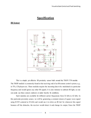
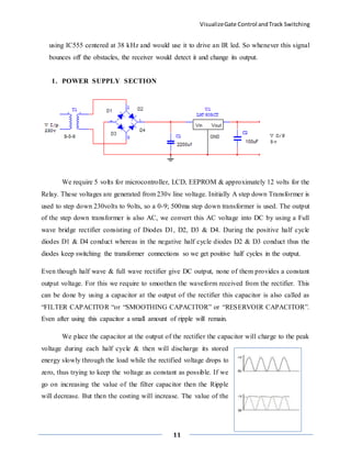
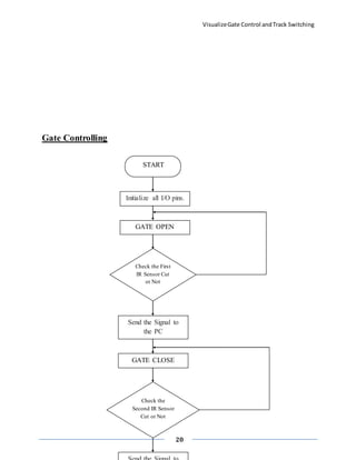
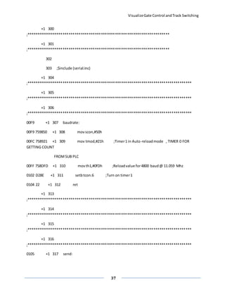
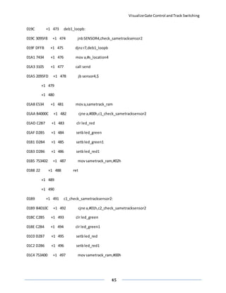
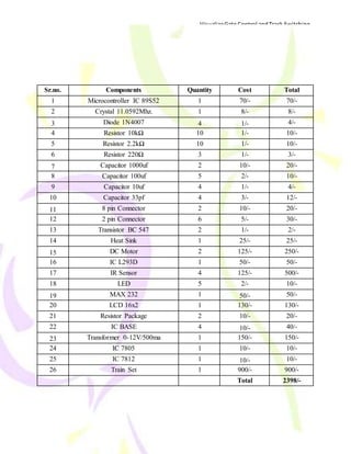
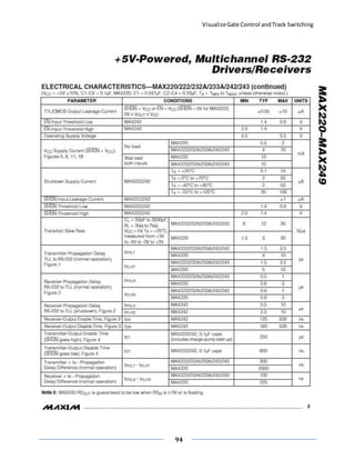
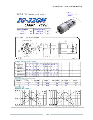
• Principle of Operation:
1. We are using the Infrared sensor (IR) pairs for detecting the train. As the train
obstructs IR signals, IR will send the received signals to the controller indicating that
the train is arrived. When the train obstructs the 1st IR sensor, it will turn ON buzzer
for particular period of time and then the gate will automatically get closed.
2. The buzzer is basically used as a warning alert for people near the railway gate.
3. We can calculate the speed of train using distance between two IR sensors (fixed) and
the time difference required by train to obstruct the 2 IR sensors.
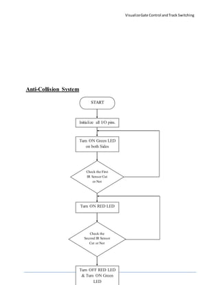
4. When the train is arriving from 1 side, the signal on the same track will indicate red
signal to opposite direction.
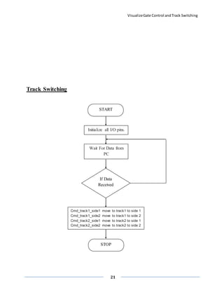
5. If we want to route the train on different tracks then we can switch the tracks using
master controller (PC).
6. These all are represented on computer (master controller) and provide master control
to operator. [I.e. gate status, signal status, tracks switching, speed measurement,
position of train.]
7. IR sensors are also used for the automatic railway gate control which is performed by
using the outputs of the IR sensors which are given to the DC motor used for the gate.
8. The status of the railway gate is represented on the PC and it is also controlled by the
master controller (PC).](https://image.slidesharecdn.com/report-151204201542-lva1-app6891/85/INTELIGENT-RAILWAY-SYSTEM-9-320.jpg)

![VisualizeGate Control andTrack Switching
23
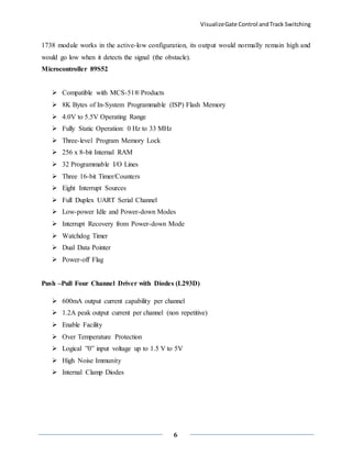
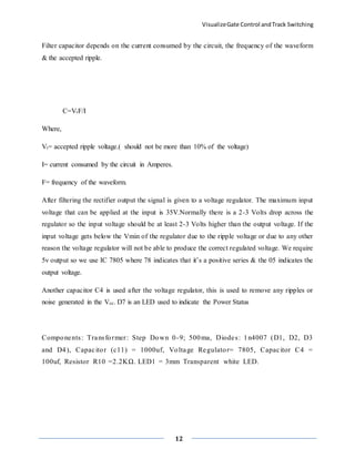
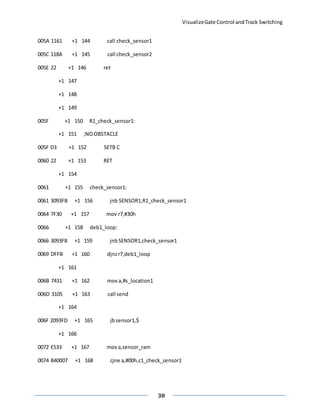
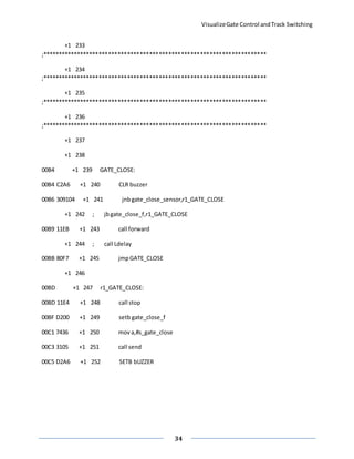
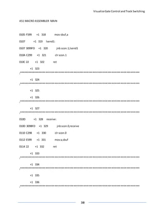
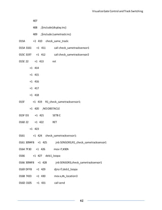
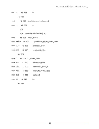
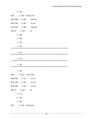
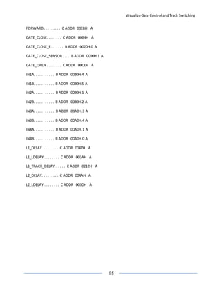
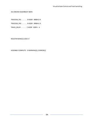
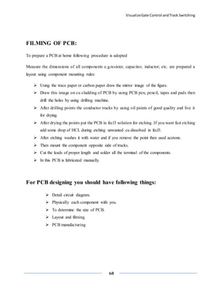
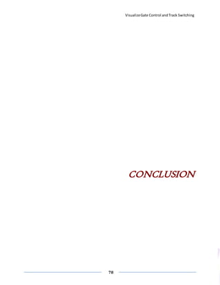
Software Listing
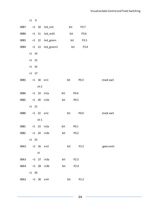
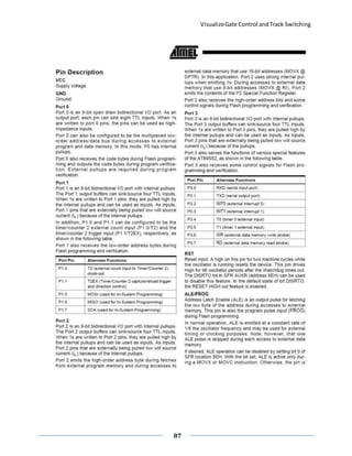
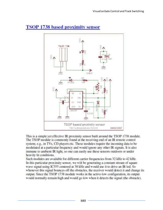
A] Assembly language programming
A51 MACRO ASSEMBLER MAIN
MACRO ASSEMBLER A51 V8.01
OBJECT MODULE PLACED IN main.OBJ
ASSEMBLER INVOKEDBY: C:KeilC51BINA51.EXEmain.asmSET(SMALL) DEBUG EP
LOC OBJ LINE SOURCE
1 ;$include (ini.inc)
0093 +1 2 SENSOR1 BIT p1.3 ;for gate
0092 +1 3 SENSOR2 BIT p1.2 ;for gate
0091 +1 4 gate_close_sensor bit P1.1
0090 +1 5 tracksw_fb1 bit P1.0
0096 +1 6 tracksw_fb2 bit P1.6
0094 +1 7 SENSOR3 BIT p1.4 ;forspeedsame tra
ck
0095 +1 8 SENSOR4 BIT p1.5 ;forsame track](https://image.slidesharecdn.com/report-151204201542-lva1-app6891/85/INTELIGENT-RAILWAY-SYSTEM-23-320.jpg)

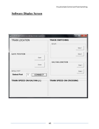
![VisualizeGate Control andTrack Switching
60
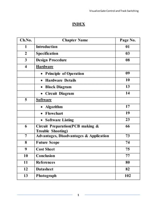
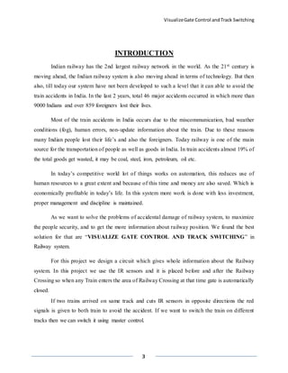
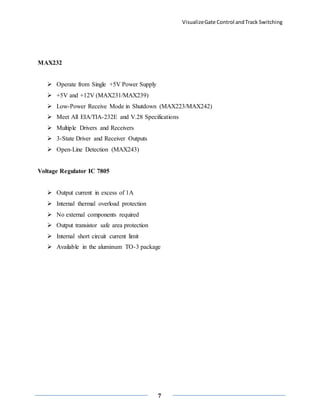
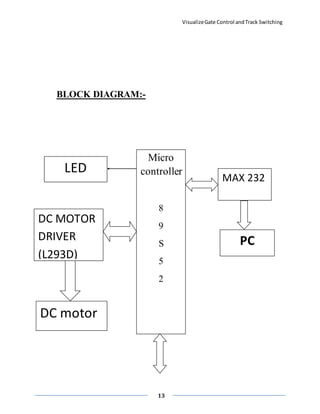
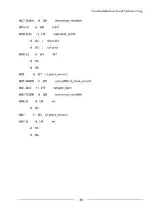
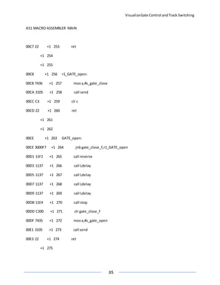
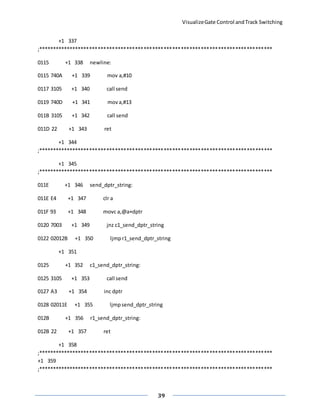
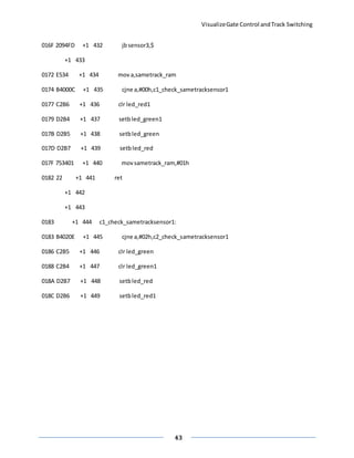
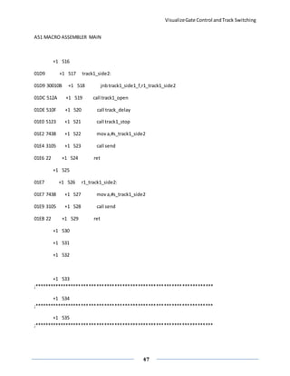
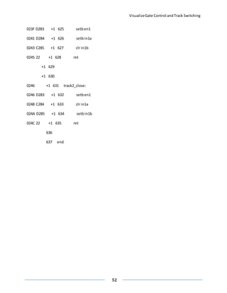
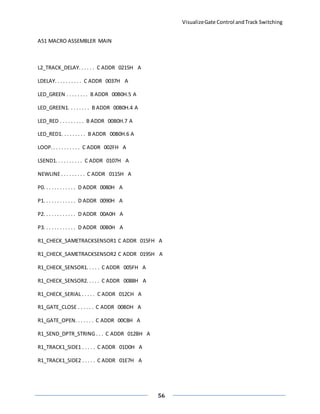
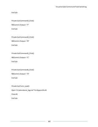
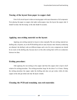
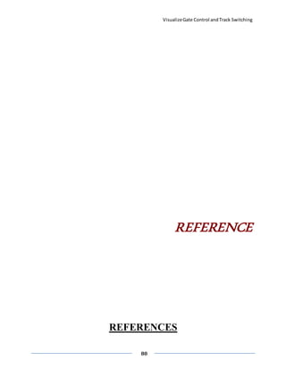
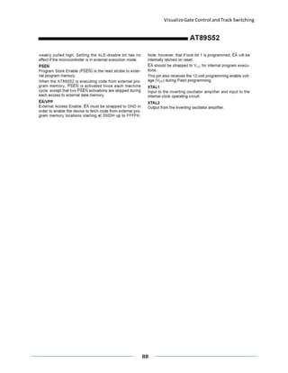
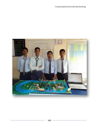
B] Visual Basic programming
OptionExplicit
DimInputStringBufferAsString
DimWriteStringBufferAsString
DimTagno As String
'Dim countAs Integer
Private Subcmdconnect_Click()
If cmdconnect.Caption="CONNECT"Then
MSComm1.CommPort= txtcommport.Text
MSComm1.PortOpen=True
cmdconnect.Caption="DISCONNECT"
MSComm1.RThreshold=1
ElseIf cmdconnect.Caption="DISCONNECT"Then
MSComm1.PortOpen=False
cmdconnect.Caption="CONNECT"
End If
End Sub
Private SubCommand1_Click()
MSComm1.Output= "E"
End Sub
Private SubCommand2_Click()
MSComm1.Output= "A"](https://image.slidesharecdn.com/report-151204201542-lva1-app6891/85/INTELIGENT-RAILWAY-SYSTEM-60-320.jpg)


The document outlines a project on 'visualize gate control and track switching' aimed at improving safety and communication in India's railway system, which suffers from accidents mainly due to human errors and inadequate technology. It describes the design and operation of hardware and software components, including IR sensors for automatic gate control, a microcontroller for processing, and a master control system for managing train track switching. The project aims to enhance safety by automating train detection and signaling to prevent collisions and accidents at railway crossings.