Downloaded 995 times
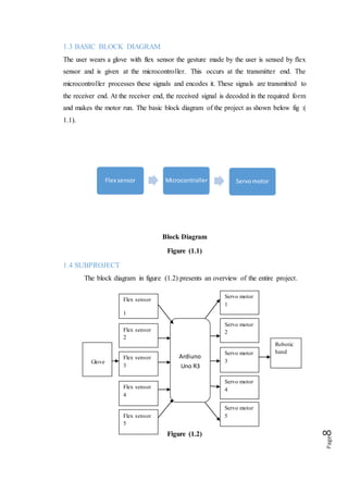
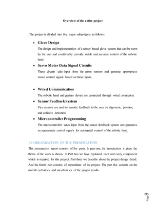
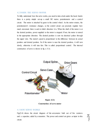

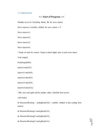
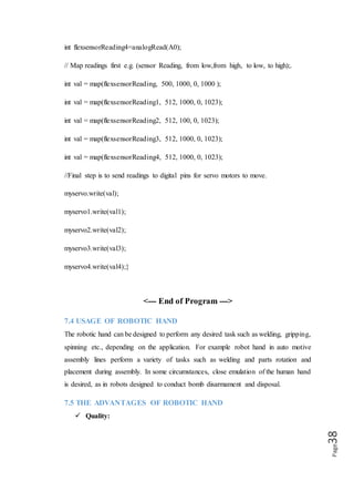
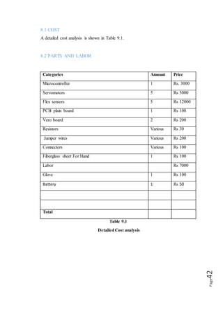


This document discusses the design and development of a robotic hand controlled by a glove. The robotic hand uses servos to mimic the motion of individual human fingers as controlled by sensors in the glove. It describes the components used - flex sensors in the glove, an Arduino microcontroller, and servos in the robotic hand. The document outlines the working principle and potential applications of this robotic hand system, such as in factories or for people with disabilities. It aims to develop a versatile robotic hand concept among business students.