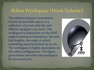
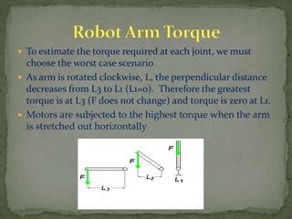
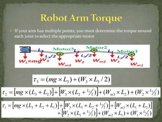
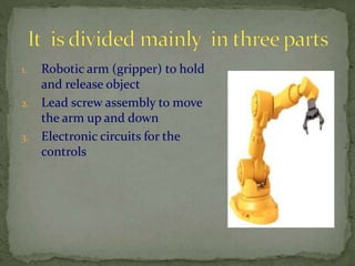
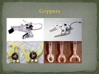
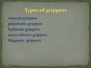
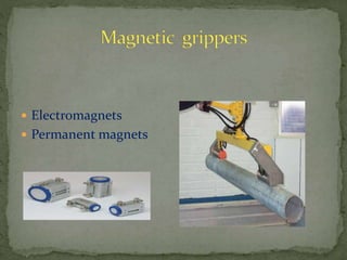
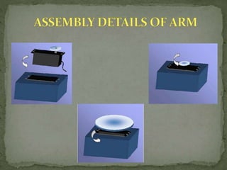
A robotic arm consists of linked segments connected by movable joints, similar to a human arm. The end of the kinematic chain that can grip or otherwise interact with its environment is called the end effector. The range of reachable positions for the end effector is defined as the robot's workspace. Proper selection of motors at each joint is important to ensure the arm can handle expected torques without failing. Common types of robot grippers include vacuum, hydraulic, pneumatic, and magnetic options, each with strengths for different applications.
Robotics and automation _ power sources and sensorsJAIGANESH SEKAR
Hydraulic, pneumatic and electric drives – determination of HP of motor and gearing ratio – variable speed arrangements – path determination – micro machines in robotics – machine vision – ranging – laser – acoustic – magnetic, fiber optic and tactile sensors.
Introduction to robotics, Laws,Classification,Types, Drives,Geometry Mohammad Ehtasham
Introduction to robotics , Basic overview ,Classification of robotics,laws of robotics,Types of robot, Robot Geometry, Robot drives, Some of the key benefits of robots in industry and society
Slide show demonstrating pick and place robot and its parts.
Also effects are implanted in the slide.
It can be helpful for students for academic projects.
Definition and origin of robotics – different types of robotics – various generations of robots – degrees of freedom – Asimov's laws of robotics – dynamic stabilization of robots.
Robotics and Autoamtion_ manipulators, actuators and end effectorsJAIGANESH SEKAR
Construction of manipulators – manipulator dynamics and force control – electronic and pneumatic manipulator control circuits – end effectors – U various types of grippers – design considerations.
Modern precision manufacturing demands extreme dimensional accuracy and surface finish.Such performance is very difficult to achieve manually, if not impossible, even with expert operators. In cases where it is possible, it takes much higher time due to the need for frequent dimensional measurement to prevent overcutting. It is thus obvious that automated motion control would replace manual “handwheel” control in modern manufacturing. Development of computer numerically controlled (CNC) machines has also made possible the automation of the machining processes with flexibility to handle production of small to medium batch of parts. In the 1940s when the U.S. Air Force perceived the need to manufacture complex parts for highspeed aircraft. This led to the development of computer-based automatic machine tool controls also known as the Numerical Control (NC) systems. Commercial production of NC machine tools started around the fifties and sixties around the world. Note that at this time the microprocessor has not yet been invented. Initially, the CNC technology was applied on lathes, milling machines, etc. which could perform a single type of metal cutting operation. Later, attempt was made to handle a variety of workpieces that may require several different types machining operations and to finish them in a single set-up. Thus CNC machining Centres capable of performing multiple operations were developed. To start with, CNC machining centres were developed for machining prismatic components combining operations like milling, drilling, boring and tapping. Gradually machines for manufacturing cylindrical components, called turning centers were developed.
Automatically controlling a machine tool based on a set of pre-programmed machining and movement instructions is known as numerical control, or NC.In a typical NC system the motion and machining instructions and the related numerical data, together called a part program, used to be written on a punched tape. The part program is arranged in the form of blocks of information, each related to a particular operation in a sequence
of operations needed for producing a mechanical component. The punched tape used to be read one block at a time. Each block contained, in a particular syntax, information needed for processing a particular machining instruction such as, the segment length, its cutting speed, feed, etc. These pieces of information were related to the final dimensions of the workpiece (length, width, and radii of circles) and the contour forms (linear, circular, or other) as per the drawing. Based on these dimensions, motion commands were given separately for each axis of motion. Other instructions and related machining parameters, such as cutting speed, feed rate, as well as auxiliary functions related to coolant flow, spindle speed, part clamping, are also provided in part programs depending on manufacturing specifications such as tolerance and surface finish. Punched tapes are mostly obsolete.
Introduction
Types of end effectors
Mechanical gripper
Other types of grippers
Tools as end effectors
The Robot/End effectors interface
Considerations in gripper selection and design
The robot is designed as a 6-axis jointed-arm kinematic system. The structural components of the robot are made of light alloy. The axes are driven by AC servomotors.
Robot Gripper for High-Mix, Low Volume AutomationRobotiq
Why can't we automate high-mix, low volume production today even though the first industrial robot was installed in 1961?
This presentation explains how we must change our mind to make this happen.
KUKA Software
Your ideas are what shapes our programs. And your daily challenges are what drives us. Whether it’s routine processes or new, tailored system solutions, KUKA supports you with the right software: from expandable system software and ready-made robotic applications, through integrated Soft PLC and wide-ranging simulation tools, right up to intelligent robot networking and safe human-machine interaction. With a familiar Windows user interface, adapted to your automation solution and 100% compatible. You can rest assured: with software from KUKA, your robots and systems are always programmed for productivity.
Robotica y programacion KUKA
La marca Kuka cuenta con varios modelos diferentes de robots con características diferentes para cubrir necesidades específicas. Los modelos los cuales haremos referencia son los siguientes:
KR 5 sixx R650.
KR 5 sixx R850.
Robotic Arm using flex sensor and servo motorjovin Richard
A robotic arm is a type of mechanical arm, usually programmable, with similar functions to a human arm; the arm may be the sum total of the mechanism or may be part of a more complex robot. we have used FLEX SENSOR for the inuput and SERVO MOTOR as output for the movement. Motor Driver L293D is used to increase the power. atmega8 is used here.
Design and Mechanism ofControlling a Robotic ArmIntroduction.docxcarolinef5
Design and Mechanism of
Controlling a Robotic Arm
Introduction:
Definition:
A robotic arm is a type of mechanical arm, usually programmable, with similar functions to a human arm; the arm may be the sum total of the mechanism or may be part of a more complex robot. The links of such a manipulator are connected by joints allowing either rotational motion (such as in an articulated robot) or translational (linear) displacement.[1][2] The links of the manipulator can be considered to form a kinematic chain. The terminus of the kinematic chain of the manipulator is called the end effector and it is analogous to the human hand.
A Robot is a virtually intelligent agent capable of carrying out tasks robotically with the
help of some supervision. Practically, a robot is basically an electro-mechanical machine
that is guided by means of computer and electronic programming. Robots can be
classified as autonomous, semiautonomous and remotely controlled. Robots are widely
used for variety of tasks such as service stations, cleaning drains, and in tasks that are
considered too dangerous to be performed by humans. A robotic arm is a robotic
manipulator, usually programmable, with similar functions to a human arm.
This Robotic arm is programmable in nature and it can be manipulated. The robotic arm
is also sometimes referred to as anthropomorphic as it is very similar to that of a human
hand. Humans today do all the tasks involved in the manufacturing industry by
themselves. However, a Robotic arm can be used for various tasks such as welding,
drilling, spraying and many more. A self-sufficient robotic arm is fabricated by using
components like micro-controllers and motors. This increases their speed of operation
and reduces the complexity. It also brings about an increase in productivity which makes
it easy to shift to hazardous materials. This specific micro
controller is used in various types of embedded applications. Robotics involves elements
of mechanical and electrical engineering, as well as control theory, computing and now
artificial intelligence.
Design of the Robotic Arm:
The Robotic Arm is designed using the Microcontroller Micro-controller using Arduino programming. This process works on the principle of
interfacing servos and Joystick. This task is achieved by using Arduino board.
Joystick play an important role The remote is fitted with joystick and the
servos are attached to the body of the robotic arm. The joystick converts the
mechanical motion into electrical motion. Hence, on the motion of the remote the
potentiometers produce the electrical pulses, which are in route for the Arduino board.
The board then processes the signals received from the joysticks and finally,
converts them into requisite digital pulses that are then sent to the servomotors. This
servo will respond with regards to the pulses which results in the moment of the arm.
Degree of Freedom:
Robot arms are described by their degrees of freedom. This number typically
ref.
A simple project on Obstacle Avoiding Robot is designed here. Robotics is an interesting and fast-growing field. Being a branch of engineering, the applications of robotics are increasing with the advancement of technology.
MOBILE CONTROLLED ROBOTIC ARM USING ARDUINO AND HC-06Eklavya Sharma
Design and control of RoboDroid to do monotonous job using a smartphone only. The robot is named ‘RoboDroid’ as it utilizes concept of both Robotics and Android.
It is a mechanical arm with movable base that is controlled by an
application through Android Smartphone via Bluetooth using a
most commonly used Bluetooth module HC-06 and programmed
with Arduino Uno. Research Paper ranked first in BITS apogee in Electronics and instrumentation.
Multi rotor drone small knowledge summary oneAlbert2019
UAV is the abbreviation of Unmanned Aerial Vehicle. It is an unmanned aircraft using radio remote control equipment and its own program control device, including unmanned helicopters, fixed-wing aircraft, multi-rotor aircraft, and unmanned airships.
NO1 Uk best vashikaran specialist in delhi vashikaran baba near me online vas...Amil Baba Dawood bangali
Contact with Dawood Bhai Just call on +92322-6382012 and we'll help you. We'll solve all your problems within 12 to 24 hours and with 101% guarantee and with astrology systematic. If you want to take any personal or professional advice then also you can call us on +92322-6382012 , ONLINE LOVE PROBLEM & Other all types of Daily Life Problem's.Then CALL or WHATSAPP us on +92322-6382012 and Get all these problems solutions here by Amil Baba DAWOOD BANGALI
#vashikaranspecialist #astrologer #palmistry #amliyaat #taweez #manpasandshadi #horoscope #spiritual #lovelife #lovespell #marriagespell#aamilbabainpakistan #amilbabainkarachi #powerfullblackmagicspell #kalajadumantarspecialist #realamilbaba #AmilbabainPakistan #astrologerincanada #astrologerindubai #lovespellsmaster #kalajaduspecialist #lovespellsthatwork #aamilbabainlahore#blackmagicformarriage #aamilbaba #kalajadu #kalailam #taweez #wazifaexpert #jadumantar #vashikaranspecialist #astrologer #palmistry #amliyaat #taweez #manpasandshadi #horoscope #spiritual #lovelife #lovespell #marriagespell#aamilbabainpakistan #amilbabainkarachi #powerfullblackmagicspell #kalajadumantarspecialist #realamilbaba #AmilbabainPakistan #astrologerincanada #astrologerindubai #lovespellsmaster #kalajaduspecialist #lovespellsthatwork #aamilbabainlahore #blackmagicforlove #blackmagicformarriage #aamilbaba #kalajadu #kalailam #taweez #wazifaexpert #jadumantar #vashikaranspecialist #astrologer #palmistry #amliyaat #taweez #manpasandshadi #horoscope #spiritual #lovelife #lovespell #marriagespell#aamilbabainpakistan #amilbabainkarachi #powerfullblackmagicspell #kalajadumantarspecialist #realamilbaba #AmilbabainPakistan #astrologerincanada #astrologerindubai #lovespellsmaster #kalajaduspecialist #lovespellsthatwork #aamilbabainlahore #Amilbabainuk #amilbabainspain #amilbabaindubai #Amilbabainnorway #amilbabainkrachi #amilbabainlahore #amilbabaingujranwalan #amilbabainislamabad
Industrial Training at Shahjalal Fertilizer Company Limited (SFCL)MdTanvirMahtab2
This presentation is about the working procedure of Shahjalal Fertilizer Company Limited (SFCL). A Govt. owned Company of Bangladesh Chemical Industries Corporation under Ministry of Industries.
About
Indigenized remote control interface card suitable for MAFI system CCR equipment. Compatible for IDM8000 CCR. Backplane mounted serial and TCP/Ethernet communication module for CCR remote access. IDM 8000 CCR remote control on serial and TCP protocol.
• Remote control: Parallel or serial interface.
• Compatible with MAFI CCR system.
• Compatible with IDM8000 CCR.
• Compatible with Backplane mount serial communication.
• Compatible with commercial and Defence aviation CCR system.
• Remote control system for accessing CCR and allied system over serial or TCP.
• Indigenized local Support/presence in India.
• Easy in configuration using DIP switches.
Technical Specifications
Indigenized remote control interface card suitable for MAFI system CCR equipment. Compatible for IDM8000 CCR. Backplane mounted serial and TCP/Ethernet communication module for CCR remote access. IDM 8000 CCR remote control on serial and TCP protocol.
Key Features
Indigenized remote control interface card suitable for MAFI system CCR equipment. Compatible for IDM8000 CCR. Backplane mounted serial and TCP/Ethernet communication module for CCR remote access. IDM 8000 CCR remote control on serial and TCP protocol.
• Remote control: Parallel or serial interface
• Compatible with MAFI CCR system
• Copatiable with IDM8000 CCR
• Compatible with Backplane mount serial communication.
• Compatible with commercial and Defence aviation CCR system.
• Remote control system for accessing CCR and allied system over serial or TCP.
• Indigenized local Support/presence in India.
Application
• Remote control: Parallel or serial interface.
• Compatible with MAFI CCR system.
• Compatible with IDM8000 CCR.
• Compatible with Backplane mount serial communication.
• Compatible with commercial and Defence aviation CCR system.
• Remote control system for accessing CCR and allied system over serial or TCP.
• Indigenized local Support/presence in India.
• Easy in configuration using DIP switches.
Explore the innovative world of trenchless pipe repair with our comprehensive guide, "The Benefits and Techniques of Trenchless Pipe Repair." This document delves into the modern methods of repairing underground pipes without the need for extensive excavation, highlighting the numerous advantages and the latest techniques used in the industry.
Learn about the cost savings, reduced environmental impact, and minimal disruption associated with trenchless technology. Discover detailed explanations of popular techniques such as pipe bursting, cured-in-place pipe (CIPP) lining, and directional drilling. Understand how these methods can be applied to various types of infrastructure, from residential plumbing to large-scale municipal systems.
Ideal for homeowners, contractors, engineers, and anyone interested in modern plumbing solutions, this guide provides valuable insights into why trenchless pipe repair is becoming the preferred choice for pipe rehabilitation. Stay informed about the latest advancements and best practices in the field.
Overview of the fundamental roles in Hydropower generation and the components involved in wider Electrical Engineering.
This paper presents the design and construction of hydroelectric dams from the hydrologist’s survey of the valley before construction, all aspects and involved disciplines, fluid dynamics, structural engineering, generation and mains frequency regulation to the very transmission of power through the network in the United Kingdom.
Author: Robbie Edward Sayers
Collaborators and co editors: Charlie Sims and Connor Healey.
(C) 2024 Robbie E. Sayers
2. A robotic arm is a type of mechanical arm,
usually programmable, with similar functions to a
human arm; the arm may be the sum total of the
mechanism or may be part of a more complex robot.
The links of such a manipulator are connected by joints
allowing either rotational motion (such as in an articulated
robot) or translational (linear) displacement.
The links of the manipulator can be considered to form
a kinematic chain. The terminus of the kinematic chain of
the manipulator is called the end effectors and it is
analogous to the human hand.
3. A degree of freedom is a joint on the arm, a place where it
can bend or rotate or translate. We can typically identify
the number of degrees of freedom by the number of
actuators on the robot arm(in case of serial arms). so for
simplicity it is treated as separate subsystem in basic robot
arm design.
4. The robot workspace (sometimes
known as reachable space) is a
collection of points that the end
effector (gripper) can reach. The
workspace is dependent on the DOF
angle/translation limitations, the arm
link lengths, the angle at which
something must be picked up at, etc.
The workspace is highly dependent on
the robot configuration. The figure
given below describes the workspace
for our serial arm.
5.
6.
7. To estimate the torque required at each joint, we must
choose the worst case scenario
As arm is rotated clockwise, L, the perpendicular distance
decreases from L3 to L1 (L1=0). Therefore the greatest
torque is at L3 (F does not change) and torque is zero at L1.
Motors are subjected to the highest torque when the arm
is stretched out horizontally
8. If your arm has multiple points, you must determine the torque around
each joint to select the appropriate motor
)2/()( 3333 LWLmg
)()()()( 2223223232
23 L
m
L
WLWLWLLmg
)()()(
)()()(
2112212
21322131231
12
3
L
m
L
m
L
WLWLW
LLWLLWLLLmg
9. 1. Robotic arm (gripper) to hold
and release object
2. Lead screw assembly to move
the arm up and down
3. Electronic circuits for the
controls
12. The vacuum gripper has been the standard in
manufacturing because of its high level of flexibility. This
type of robot gripper uses a rubber or polyurethane suction
cup to pick up items. Some vacuum grippers use a closed-
cell foam rubber layer, rather than suction cups, to
complete the application.
13. The hydraulic gripper provides the most strength and is
often used for applications that require significant amounts
of force. These robotic grippers generate their strength
from pumps that can provide up to 2000psi. Although they
are strong, hydraulic grippers are messier than other
grippers due to the oil used in the pumps. They also may
need more maintenance due the gripper being damaged
because of the force used during the application.
14. The pneumatic gripper is popular due to its compact size
and light weight. It can easily be incorporated into tight
spaces, which can be helpful in the manufacturing
industry. Pneumatic robot grippers can either be opened or
closed, earning them the nickname “bang bang” actuators,
because of the noise created when the metal-on-
metal gripper operates.
15. The servo-electric gripper appears more and more in
industrial settings, due to the fact that it is easy to
control. Electronic motors control the movement of
the gripper jaws. These grippers are highly flexible and
allow for different material tolerances
when handling parts. Servo-electric grippers are also
cost effective because they are clean and have no air
lines.
17. Electromagnetic grippers include a controller unit and
a DC power for handling the materials. This type of
grippers is easy to control, and very effective in releasing
the part at the end of the operation than the permanent
magnets. If the work part gripped is to be released, the
polarity level is minimized by the controller unit before the
electromagnet is turned off. This process will certainly help
in removing the magnetism on the work parts. As a result, a
best way of releasing the materials is possible in this
gripper.
18. The permanent magnets do not require any sort of external
power as like the electromagnets for handling the
materials. After this gripper grasps a work part, an
additional device called asstripper push – off pin will be
required to separate the work part from the magnet. This
device is incorporated at the sides of the gripper.
The advantage of this permanent magnet gripper is that it
can be used in hazardous applications like explosion-proof
apparatus because of no electrical circuit. Moreover, there
is no possibility of spark production as well.
19. In constructing the arm, we made use of five servo motors (including
gripper) since our structure allows movement in all three dimensions.
There is a servo motor at the base, which allows for angular movement
of the whole structure; other two at the shoulder and elbow to allow the
upward and downward movement of the arm; one for the movement of
the wrist while the last servo motor at the end effector allows for the
gripping of objects.
The serial arm is a four degree of freedom system. Three DOF control
the position of the arm in the Cartesian pace, one for wrist orientation
and one additional servo for actuating gripper.
20.
21.
22.
23. Industrial robots have various axis
configurations. The vast majority
of articulated robots,
however, feature six axes, also
called six degrees of freedom. Six
axis robots allow for greater
flexibility and can perform a
wider variety of applications than
robots with fewer axes.
24.
25.
26. Servos are a special type of DC motors with built in gearing and
feedback control loop circuitry and they don’t require motor
controllers. These motors are mainly developed for making robots,
toys, etc. that are mainly used for education and not for industrial
applications.
Servos are becoming extremely popular with robot, RC plane, and RC
boat builders. Most servo motors can rotate about 90 to 180 degrees.
Some rotate through a full 360 degrees or more. However, servos are
unable to continually rotate, meaning they can't be used for driving
wheels (unless modified), but their precision positioning makes them
ideal for robot arms and legs, rack and pinion steering, and sensor
scanners to name a few. Since servos are fully self contained, the
velocity and angle control loops are very easy to implement. To use a
servo, we connect the black wire to ground, the red to a 4.8-6V source,
and the yellow/white wire to a signal source (such as from your
microcontroller). Vary the square wave pulse width from 1-2ms and the
servo is now position/velocity controlled.
27. Servo Wiring:
All servos have three
wires:
Black or Brown is for
ground.
Red is for power (~4.8-
6V).
Yellow, Orange, or White
is the signal wire (3-5V).
Servo Voltage (Red and
Black/Brown wires):
Servos can operate under a
range of voltages. Typical
operation is from 4.8V to 6V.
There are a
few micro sized servos that can
operate at less, and now a few
Hitec servos that operate at
much
more.
28. While the black and red wires provide power to the motor, the signal
wire is what we use to command the servo. The general concept is to
simply send an ordinary logic square wave to your servo at a specific
wave length (50Hz), and the servo goes to a particular angle. The
wavelength directly maps to servo angle. In our case Arduino Mega
takes input from the PC and generates
the corresponding square wave, which in turn controls the angular
position of the servo motor.
The standard time vs. angle is represented in this chart:
29. Overview
An Arduino is a single-board microcontroller and a software suite for
programming. It is designed for an Atmel AVR processor and features
on-board I/O support. The software consists of a standard
programming language and the boot loader that runs on the board.
We are using Arduino Mega microcontroller board based on the
ATmega1280.
It has 54 digital input/output pins (of which 14 can be used as PWM
outputs), 16 analog inputs, 4 UARTs (hardware serial ports), a 16 MHz
crystal oscillator, a USB connection, a power jack, an ICSP header, and
a reset button.
It contains everything needed to support the microcontroller; simply
connect it to a computer with a USB cable or power it with an AC-to-DC
adapter or battery to get started.
30.
31. •POWER: The Arduino Mega can be powered via the USB connection or with
an external
•power supply: The power source is selected automatically.
•The power pins are as follows:
•VIN: The input voltage to the Arduino board when it's using an external power
source.
•5V: The regulated power supply used to power the microcontroller and other
components on the board.
•3V3: 3.3 volt supply generated by the on-board FTDI chip. Maximum current
draw is 50 mA.
•GND: Ground pins.
•MEMORY: The ATMEGA 1280 has 128 KB of flash memory for storing
code.
•COMMUNICATION: The Arduino software includes a serial monitor
which allows simple textual data to be sent to and from the Arduino board. The RX
and TX LEDs on the board will flash when data is being transmitted via the FTDI
chip and USB connection to the computer (but not for serial communication on
pins 0 and 1. It has a number of facilities for communication with a computer,
another Arduino, or other microcontrollers.
32. In this tutorial, we assume you're using an Arduino Mega.
The Arduino is a simple board that contains everything you need to start working
with electronics and microcontroller programming. This diagram illustrates the
major components of an Arduino Mega.
You also need a standard USB cable (A plug to B plug): the kind you would connect
to a USB
printer, for example.
33. 7805 is a 5V fixed three terminal positive voltage regulator IC. The IC has features
such as safe operating area protection, thermal shut down, internal current limiting
which makes the IC very rugged. Output currents up to 1A can be drawn from the IC
provided that there is a proper heat sink. A 9V transformer steps down the main
voltage, 1A bridge rectifies it and capacitor C1 filters it and 7805 regulates it to
produce a steady 5Volt DC. The circuit schematic is given below.
Circuit diagram with Parts list.
34.
35. Servomotors are special position motors. They are
often used in RC airplanes, RC cars and robots,
where a precise position is required. You can easily
find them in a RC specialized store.
A typical servomotor consists in a DC motor
connected with a control circuit and a gear box. The
gear box converts the DC motor into torque. The
control circuit has a potentiometer for feedback, so it
can read the current position and adjust
it automatically. A servomotor can't do a complete
turn, they go up to 90 or 180 degress.
A servomotor has 3 wires: red (V+), black (GND) and
white or yellow (SIGNAL). The red and black are the
power supply wires and the third is for control.
To control a servomotor, power it with 5V and supply
the control wire with a voltage from 0 to V+, the
position will be proportional to the Signal voltage. To
test it, connect it like this: