Downloaded 117 times

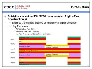
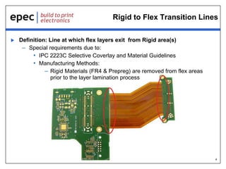

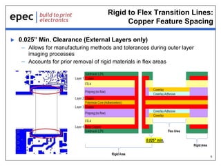
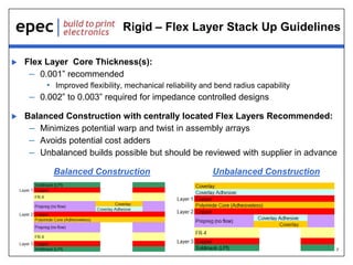
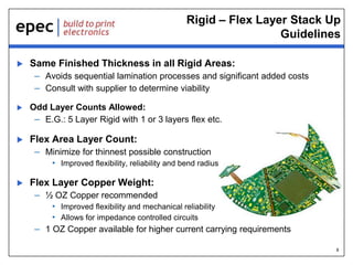


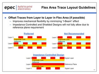
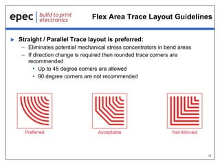


The document outlines guidelines for rigid-flex circuit design, emphasizing the importance of adhering to IPC standards for construction and layout to enhance reliability and performance. Key points include requirements for flex layer stack up, spacing of transition lines, and trace layout to ensure mechanical flexibility while minimizing risk during manufacturing. Additional resources and support for design and engineering are available to assist customers.