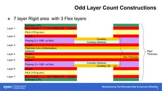
Manufacturing That Eliminates Risk & Improves Reliability
Advanced Rigid-Flex
Circuit Constructions
06.29.17
Manufacturing That Eliminates Risk & Improves Reliability
2
Introduction
 Todays Rigid-Flex materials and construction methods allow for a
wide variety of advanced design configurations.
 These options create the opportunity to achieve higher levels of
design integration and packing density.
Manufacturing That Eliminates Risk & Improves Reliability
3
Introduction
 Options Include:
– Higher Flex Layer Counts
– Blind & Buried Via Structures
– ZIF Connections
– Flex Area Components
– Asymmetrical Constructions
– Shielded Flex Areas
– Multiple Rigid Area Thicknesses
 In this webinar we will introduce and discuss the benefits and applications of
some of the more common advanced rigid-flex circuit board constructions.
 Many additional configurations and combinations are available.
Manufacturing That Eliminates Risk & Improves Reliability
4
Agenda
 Standard Construction Review
 Advanced Rigid-Flex Construction Options:
– Odd Number Layer Counts
– Asymmetrical Constructions
– Varying Flex Layer Count Areas
– Integrated ZIF Connections
– Blind & Buried Vias
– Air Gap Flex Layer Constructions
– Multiple Rigid Area Thicknesses
– Shielded Flex Layers
Manufacturing That Eliminates Risk & Improves Reliability
5
Standard Rigid-Flex Construction
 Symmetrical construction
 Even layer counts in both rigid & flex areas
 Impedance Control available
Manufacturing That Eliminates Risk & Improves Reliability
6
Standard Rigid-Flex Construction
 Most common construction (approx. 60%)
Soldmask (LPI)
Layer 1 Base Copper um + Plated 20 um min.
FR-4 (170 tg min.)
Layer 2 Copper
Coverlay:
Coverlay Adhesive:
Layer 3 Copper
Polyimide Core (Adhesiveless) Flex Thickness Rigid
Layer 4 Copper Thickness
Coverlay Adhesive:
Coverlay:
Layer 5 Copper
FR-4 (170 tg min.)
Layer 6 Base Copper um + Plated 20 um min.
Soldmask (LPI)
Prepreg (2 x 1080, no flow)
Manufacturing That Eliminates Risk & Improves Reliability
7
Odd Layer Count Constructions
 7 layer Rigid area with 3 Flex layers
Soldmask (LPI)
Layer 1 Base Copper um + Plated 20 um min.
FR-4 (170 tg min.)
Layer 2 Copper
Coverlay:
Coverlay Adhesive:
Layer 3 Copper
Polyimide Core (Adhesiveless)
Adhesive Rigid
Layer 4 Copper Thickness
Polyimide Flex Thickness
Layer 5 Copper
Coverlay Adhesive:
Coverlay: 25 um
Layer 6 Copper
FR-4 (170 tg min.)
Layer 7 Base Copper um + Plated 20 um min.
Soldmask (LPI)
Prepreg (2 x 1080, no flow)
Manufacturing That Eliminates Risk & Improves Reliability
8
Odd Layer Count Constructions
 5 layer Rigid area with 1 Flex layer
Soldmask (LPI)
Layer 1 Base Copper um + Plated 20 um min.
FR-4 (170 tg min.)
Layer 2 Copper
Coverlay:
Coverlay Adhesive:
Layer 3 Copper Flex Thickness Rigid
Polyimide Core (Adhesiveless) Thickness
Layer 4 Copper
FR-4 (170 tg min.)
Layer 5 Base Copper um + Plated 20 um min.
Soldmask (LPI)
Prepreg (2 x 1080, no flow)
Manufacturing That Eliminates Risk & Improves Reliability
9
Odd Layer Count Constructions
 3 layer Flex area configuration allows for two sided shielding requirements in
flex areas.
– Stripline Impedance Control
– RF & EMI Requirements
 Odd layer counts can apply to both flex & rigid areas independent of each
other.
 Minimizes flex area thickness for improved flexibility and mechanical bend
capability / reliability.
 IPC 2223C compliant.
 Reduces cost by minimizing total number of flex layers required.
Manufacturing That Eliminates Risk & Improves Reliability
10
Asymmetrical Constructions
 Applications:
– Convoluted impedance requirements
– Blind via constructions
• Minimizes blind via aspect ratio for improved manufacturability reliability.
 May result in warp & twist in assembly array
which may require a hold down fixture
for transport through assembly.
Manufacturing That Eliminates Risk & Improves Reliability
11
Asymmetrical Constructions
Soldmask (LPI)
Layer 1 Base Copper 18 um + Plated 35 um min.
FR-4 (170 tg min.)
Layer 2 Copper
Prepreg (1 x 1080, no flow)
Layer 3 Copper
FR-4 (170 tg min.)
Layer 4 Copper Rigid
Coverlay: Thickness
Coverlay Adhesive:
Layer 5 Copper
Polyimide Core (Adhesiveless) Flex Thickness
Layer 6 Copper
Coverlay Adhesive:
Coverlay:
Layer 7 Copper
FR-4 (170 tg min.)
Layer 8 Base Copper 18 um + Plated 35 um min.
Prepreg (2 x 1080, no flow)
Prepreg (1 x 1080, no flow)
Manufacturing That Eliminates Risk & Improves Reliability
12
Varying Flex Layer Count Constructions
 Allows for tighter bend capabilities in reduced flex layer count area.
 Multiple configurations available.
 Requires use of “Air Gap” flex layer construction.
Manufacturing That Eliminates Risk & Improves Reliability
13
Varying Flex Layer Count Constructions
Soldmask
Layer 1 Base Copper um + Plated 20 um min.
FR-4 (170 tg min.)
Coverlay:
Coverlay Adhesive:
Layer 2 Copper
Polyimide Core (Adhesiveless) Flex
Layer 3 Copper Thickness
Coverlay Adhesive:
Coverlay: Rigid
Thickness
Coverlay:
Coverlay Adhesive:
Layer 4 Copper
Polyimide Core (Adhesiveless) Flex
Layer 5 Copper Thickness
Coverlay Adhesive:
Coverlay:
FR-4 (170 tg min.)
Layer 6 Base Copper um + Plated 20 um min.
Soldmask
AIR GAP
Prepreg (2 x 1080, no flow)
Prepreg (3 x 1080, no flow)
Prepreg (2 x 1080, no flow)
Manufacturing That Eliminates Risk & Improves Reliability
14
Integrated ZIF Tail Constructions
 Eliminates the need for a ZIF
connector and separate flex circuit.
 Reduces real-estate requirements in
rigid area(s).
 Improves reliability through
elimination of points of interconnect.
– ZIF connector solder joints, ZIF
finger contacts
 Available in a wide variety of
configurations.
Manufacturing That Eliminates Risk & Improves Reliability
15
Integrated ZIF Tail Constructions
Soldmask (LPI)
Layer 1 Base Copper 35 um + Plated 20 um min.
ZIF
Adhesive Thickness
Polyimide Core (Adhesiveless) Rigid Thickness Flex Thickness
Layer 2 Copper
Coverlay Adhesive:
Coverlay:
Layer 3 Base Copper 35 um + Plated 20 um min.
Soldmask (LPI)
Prepreg (2 x 1080, no flow)
FR-4 (170 tg min.)
Polyimde Stiffener
FR-4 (170 tg min.)
Manufacturing That Eliminates Risk & Improves Reliability
16
Blind & Buried Constructions
 Applications: Similar to Rigid PCB Blind & Buried Constructions
– High density BGA applications with via in pad etc.
 May require an asymmetrical construction if blind vias interconnect to
flex layers.
 Configurations may be limited due to number of sequential lamination
cycles required. Less than Rigid PCBs due to material dimensional
tolerances and manufacturing methods.
 Via fill and cap available.
Manufacturing That Eliminates Risk & Improves Reliability
17
Blind & Buried Constructions
Soldmask (LPI)
Layer 1 Base Copper 18 um + Plated 35 um min.
FR-4 (170 tg min.)
Layer 2 Copper
Prepreg (1 x 1080, no flow)
Layer 3 Copper
FR-4 (170 tg min.)
Layer 4 Copper
Coverlay:
Coverlay Adhesive:
Layer 5 Copper
Polyimide Core (Adhesiveless) Flex Thickness Rigid
Layer 6 Copper Thickness
Coverlay Adhesive:
Coverlay:
Layer 7 Copper
FR-4 (170 tg min.)
Layer 8 Base Copper 18 um + Plated 35 um min.
Prepreg (2 x 1080, no flow)
Prepreg (1 x 1080, no flow)
Manufacturing That Eliminates Risk & Improves Reliability
18
Flex Layer Air Gap Constructions
 Flex layers configured as independent pairs of 2.
 Allows design to meet IPC 2223C design guidelines.
– Construction results in no flex adhesives in rigid areas.
– Preferred configuration for 4 or more flex layers.
 Provides greater flexibility due to flex layers bending
independent of each other.
Manufacturing That Eliminates Risk & Improves Reliability
19
Flex Layer Air Gap Constructions
Soldmask
Layer 1 Base Copper um + Plated 20 um min.
FR-4 (170 tg min.)
Coverlay:
Coverlay Adhesive:
Layer 2 Copper
Polyimide Core (Adhesiveless)
Layer 3 Copper
Coverlay Adhesive:
Coverlay:
Coverlay:
Coverlay Adhesive:
Layer 4 Copper Rigid
Polyimide Core (Adhesiveless) Flex Thickness Thickness
Layer 5 Copper
Coverlay Adhesive:
Coverlay:
Coverlay:
Coverlay Adhesive:
Layer 6 Copper
Polyimide Core (Adhesiveless)
Layer 7 Copper
Coverlay Adhesive:
Coverlay:
FR-4 (170 tg min.)
Layer 8 Base Copper um + Plated 20 um min.
Prepreg (3 x 1080, no flow) AIR GAP
AIR GAP
Prepreg (2 x 1080, no flow)
Prepreg (3 x 1080, no flow)
Prepreg (2 x 1080, no flow)
Manufacturing That Eliminates Risk & Improves Reliability
20
Multiple Rigid Area Thickness Construction
 Rigid area thickness vary between sections.
 Practically limited to 2 rigid thicknesses maximum.
 May have limits in rigid area thicknesses due to required materials.
 Very costly construction
– Manufacturing process is equivalent to making 2 boards to get 1.
Manufacturing That Eliminates Risk & Improves Reliability
21
Multiple Rigid Area Thickness Construction
Soldmask (LPI)
Layer 1 Base Copper 18 um + Plated 30 um min.
Soldmask (LPI)
Layer 2 Copper + Plating
Coverlay:
Coverlay Adhesive:
Layer 3 Copper
Polyimide Core (Adhesiveless) Rigid Thickness 1 Rigid
Layer 4 Copper Thickness 2
Coverlay Adhesive:
Coverlay:
Layer 5 Copper + Plating
Soldmask (LPI)
Layer 6 Base Copper 18 um + Plated 30 um min.
Prepreg
Prepreg
FR-4 (170 tg min.)
FR-4 (170 tg min.)
Prepreg (1 x 10⁶, + 1 x 1080, no flow)
Prepreg (2 x 1060, no flow)
Manufacturing That Eliminates Risk & Improves Reliability
22
Shielded Flex Layers Construction
 Allows for effective EMI & RF shielding without additional copper
layers.
– Reduced cost
– Thinner flex area construction for improved flexibility
 Uses specialized shielding films (i.e.: Tatsuta, APlus etc.)
 Shielding films are laminated to Flex area
Coverlays and interconnect to ground
through selective Coverlay openings and
electrically conductive adhesive.
Manufacturing That Eliminates Risk & Improves Reliability
23
Shielded Flex Layers Construction
Soldmask (LPI)
Layer 1 Base Copper um + Plated 25 um min.
Shield Layer
Coverlay:
Coverlay Adhesive:
Layer 2 Copper
Polyimide Core (Adhesiveless) Flex Thickness Rigid
Layer 3 Copper Thickness
Coverlay Adhesive:
Coverlay:
Shield Layer
Layer 4 Base Copper um + Plated 25 um min.
FR-4 (170 tg min.)
FR-4 (170 tg min.)
Prepreg (2 x 1080 no flow)
Manufacturing That Eliminates Risk & Improves Reliability
24
Summary
 The combination of todays Rigid PCB and Flex circuit technology
allows for a very wide variety of Rigid-Flex constructions that can add
a significant amount of functionality, integration and overall packaging
reduction to a design.
 Majority of the specific constructions can also be combined together to
create an almost endless number of configurations.
Manufacturing That Eliminates Risk & Improves Reliability
25
Our Products
Custom Battery Packs Flex & Rigid-Flex PCB’s High Reliability SMART HMIs
RF Product Solutions Cable Assemblies Printed Circuit Boards
Manufacturing That Eliminates Risk & Improves Reliability
26
Design Centers & Technical Support
 Battery Pack & Power Management – Denver, CO
 SMART User Interfaces – Largo, FL
 Flex & Rigid Flex – Toronto, Canada
 RF Products – New Bedford, MA & Largo, FL
 Cable Assemblies – Largo, FL
 Printed Circuit Boards – New Bedford, MA & Shenzhen, China
 Our Engineering and Design teams are ready to help our
customers create world class and cost effective product
solutions.
Manufacturing That Eliminates Risk & Improves Reliability
27
Q&A
 Questions?
– Enter any questions you may have
in the Control Panel
– If we don’t have time to get to it, we
will reply via email
Manufacturing That Eliminates Risk & Improves Reliability
28
Thank You
Check out our website at www.epectec.com.
For more information email sales@epectec.com.
Stay Connected with Epec Engineered Technologies
Follow us on our social media sites for continuous technical updates and information:

Advanced Rigid-Flex Circuit Constructions

  • 1.
    Manufacturing That EliminatesRisk & Improves Reliability Advanced Rigid-Flex Circuit Constructions 06.29.17
  • 2.
    Manufacturing That EliminatesRisk & Improves Reliability 2 Introduction  Todays Rigid-Flex materials and construction methods allow for a wide variety of advanced design configurations.  These options create the opportunity to achieve higher levels of design integration and packing density.
  • 3.
    Manufacturing That EliminatesRisk & Improves Reliability 3 Introduction  Options Include: – Higher Flex Layer Counts – Blind & Buried Via Structures – ZIF Connections – Flex Area Components – Asymmetrical Constructions – Shielded Flex Areas – Multiple Rigid Area Thicknesses  In this webinar we will introduce and discuss the benefits and applications of some of the more common advanced rigid-flex circuit board constructions.  Many additional configurations and combinations are available.
  • 4.
    Manufacturing That EliminatesRisk & Improves Reliability 4 Agenda  Standard Construction Review  Advanced Rigid-Flex Construction Options: – Odd Number Layer Counts – Asymmetrical Constructions – Varying Flex Layer Count Areas – Integrated ZIF Connections – Blind & Buried Vias – Air Gap Flex Layer Constructions – Multiple Rigid Area Thicknesses – Shielded Flex Layers
  • 5.
    Manufacturing That EliminatesRisk & Improves Reliability 5 Standard Rigid-Flex Construction  Symmetrical construction  Even layer counts in both rigid & flex areas  Impedance Control available
  • 6.
    Manufacturing That EliminatesRisk & Improves Reliability 6 Standard Rigid-Flex Construction  Most common construction (approx. 60%) Soldmask (LPI) Layer 1 Base Copper um + Plated 20 um min. FR-4 (170 tg min.) Layer 2 Copper Coverlay: Coverlay Adhesive: Layer 3 Copper Polyimide Core (Adhesiveless) Flex Thickness Rigid Layer 4 Copper Thickness Coverlay Adhesive: Coverlay: Layer 5 Copper FR-4 (170 tg min.) Layer 6 Base Copper um + Plated 20 um min. Soldmask (LPI) Prepreg (2 x 1080, no flow) Prepreg (2 x 1080, no flow)
  • 7.
    Manufacturing That EliminatesRisk & Improves Reliability 7 Odd Layer Count Constructions  7 layer Rigid area with 3 Flex layers Soldmask (LPI) Layer 1 Base Copper um + Plated 20 um min. FR-4 (170 tg min.) Layer 2 Copper Coverlay: Coverlay Adhesive: Layer 3 Copper Polyimide Core (Adhesiveless) Adhesive Rigid Layer 4 Copper Thickness Polyimide Flex Thickness Layer 5 Copper Coverlay Adhesive: Coverlay: 25 um Layer 6 Copper FR-4 (170 tg min.) Layer 7 Base Copper um + Plated 20 um min. Soldmask (LPI) Prepreg (2 x 1080, no flow) Prepreg (2 x 1080, no flow)
  • 8.
    Manufacturing That EliminatesRisk & Improves Reliability 8 Odd Layer Count Constructions  5 layer Rigid area with 1 Flex layer Soldmask (LPI) Layer 1 Base Copper um + Plated 20 um min. FR-4 (170 tg min.) Layer 2 Copper Coverlay: Coverlay Adhesive: Layer 3 Copper Flex Thickness Rigid Polyimide Core (Adhesiveless) Thickness Layer 4 Copper FR-4 (170 tg min.) Layer 5 Base Copper um + Plated 20 um min. Soldmask (LPI) Prepreg (2 x 1080, no flow) Prepreg (2 x 1080, no flow)
  • 9.
    Manufacturing That EliminatesRisk & Improves Reliability 9 Odd Layer Count Constructions  3 layer Flex area configuration allows for two sided shielding requirements in flex areas. – Stripline Impedance Control – RF & EMI Requirements  Odd layer counts can apply to both flex & rigid areas independent of each other.  Minimizes flex area thickness for improved flexibility and mechanical bend capability / reliability.  IPC 2223C compliant.  Reduces cost by minimizing total number of flex layers required.
  • 10.
    Manufacturing That EliminatesRisk & Improves Reliability 10 Asymmetrical Constructions  Applications: – Convoluted impedance requirements – Blind via constructions • Minimizes blind via aspect ratio for improved manufacturability reliability.  May result in warp & twist in assembly array which may require a hold down fixture for transport through assembly.
  • 11.
    Manufacturing That EliminatesRisk & Improves Reliability 11 Asymmetrical Constructions Soldmask (LPI) Layer 1 Base Copper 18 um + Plated 35 um min. FR-4 (170 tg min.) Layer 2 Copper Prepreg (1 x 1080, no flow) Layer 3 Copper FR-4 (170 tg min.) Layer 4 Copper Rigid Coverlay: Thickness Coverlay Adhesive: Layer 5 Copper Polyimide Core (Adhesiveless) Flex Thickness Layer 6 Copper Coverlay Adhesive: Coverlay: Layer 7 Copper FR-4 (170 tg min.) Layer 8 Base Copper 18 um + Plated 35 um min. Prepreg (2 x 1080, no flow) Prepreg (1 x 1080, no flow)
  • 12.
    Manufacturing That EliminatesRisk & Improves Reliability 12 Varying Flex Layer Count Constructions  Allows for tighter bend capabilities in reduced flex layer count area.  Multiple configurations available.  Requires use of “Air Gap” flex layer construction.
  • 13.
    Manufacturing That EliminatesRisk & Improves Reliability 13 Varying Flex Layer Count Constructions Soldmask Layer 1 Base Copper um + Plated 20 um min. FR-4 (170 tg min.) Coverlay: Coverlay Adhesive: Layer 2 Copper Polyimide Core (Adhesiveless) Flex Layer 3 Copper Thickness Coverlay Adhesive: Coverlay: Rigid Thickness Coverlay: Coverlay Adhesive: Layer 4 Copper Polyimide Core (Adhesiveless) Flex Layer 5 Copper Thickness Coverlay Adhesive: Coverlay: FR-4 (170 tg min.) Layer 6 Base Copper um + Plated 20 um min. Soldmask AIR GAP Prepreg (2 x 1080, no flow) Prepreg (3 x 1080, no flow) Prepreg (2 x 1080, no flow)
  • 14.
    Manufacturing That EliminatesRisk & Improves Reliability 14 Integrated ZIF Tail Constructions  Eliminates the need for a ZIF connector and separate flex circuit.  Reduces real-estate requirements in rigid area(s).  Improves reliability through elimination of points of interconnect. – ZIF connector solder joints, ZIF finger contacts  Available in a wide variety of configurations.
  • 15.
    Manufacturing That EliminatesRisk & Improves Reliability 15 Integrated ZIF Tail Constructions Soldmask (LPI) Layer 1 Base Copper 35 um + Plated 20 um min. ZIF Adhesive Thickness Polyimide Core (Adhesiveless) Rigid Thickness Flex Thickness Layer 2 Copper Coverlay Adhesive: Coverlay: Layer 3 Base Copper 35 um + Plated 20 um min. Soldmask (LPI) Prepreg (2 x 1080, no flow) Prepreg (2 x 1080, no flow) FR-4 (170 tg min.) Polyimde Stiffener FR-4 (170 tg min.)
  • 16.
    Manufacturing That EliminatesRisk & Improves Reliability 16 Blind & Buried Constructions  Applications: Similar to Rigid PCB Blind & Buried Constructions – High density BGA applications with via in pad etc.  May require an asymmetrical construction if blind vias interconnect to flex layers.  Configurations may be limited due to number of sequential lamination cycles required. Less than Rigid PCBs due to material dimensional tolerances and manufacturing methods.  Via fill and cap available.
  • 17.
    Manufacturing That EliminatesRisk & Improves Reliability 17 Blind & Buried Constructions Soldmask (LPI) Layer 1 Base Copper 18 um + Plated 35 um min. FR-4 (170 tg min.) Layer 2 Copper Prepreg (1 x 1080, no flow) Layer 3 Copper FR-4 (170 tg min.) Layer 4 Copper Coverlay: Coverlay Adhesive: Layer 5 Copper Polyimide Core (Adhesiveless) Flex Thickness Rigid Layer 6 Copper Thickness Coverlay Adhesive: Coverlay: Layer 7 Copper FR-4 (170 tg min.) Layer 8 Base Copper 18 um + Plated 35 um min. Prepreg (2 x 1080, no flow) Prepreg (1 x 1080, no flow)
  • 18.
    Manufacturing That EliminatesRisk & Improves Reliability 18 Flex Layer Air Gap Constructions  Flex layers configured as independent pairs of 2.  Allows design to meet IPC 2223C design guidelines. – Construction results in no flex adhesives in rigid areas. – Preferred configuration for 4 or more flex layers.  Provides greater flexibility due to flex layers bending independent of each other.
  • 19.
    Manufacturing That EliminatesRisk & Improves Reliability 19 Flex Layer Air Gap Constructions Soldmask Layer 1 Base Copper um + Plated 20 um min. FR-4 (170 tg min.) Coverlay: Coverlay Adhesive: Layer 2 Copper Polyimide Core (Adhesiveless) Layer 3 Copper Coverlay Adhesive: Coverlay: Coverlay: Coverlay Adhesive: Layer 4 Copper Rigid Polyimide Core (Adhesiveless) Flex Thickness Thickness Layer 5 Copper Coverlay Adhesive: Coverlay: Coverlay: Coverlay Adhesive: Layer 6 Copper Polyimide Core (Adhesiveless) Layer 7 Copper Coverlay Adhesive: Coverlay: FR-4 (170 tg min.) Layer 8 Base Copper um + Plated 20 um min. Prepreg (3 x 1080, no flow) AIR GAP AIR GAP Prepreg (2 x 1080, no flow) Prepreg (3 x 1080, no flow) Prepreg (2 x 1080, no flow)
  • 20.
    Manufacturing That EliminatesRisk & Improves Reliability 20 Multiple Rigid Area Thickness Construction  Rigid area thickness vary between sections.  Practically limited to 2 rigid thicknesses maximum.  May have limits in rigid area thicknesses due to required materials.  Very costly construction – Manufacturing process is equivalent to making 2 boards to get 1.
  • 21.
    Manufacturing That EliminatesRisk & Improves Reliability 21 Multiple Rigid Area Thickness Construction Soldmask (LPI) Layer 1 Base Copper 18 um + Plated 30 um min. Soldmask (LPI) Layer 2 Copper + Plating Coverlay: Coverlay Adhesive: Layer 3 Copper Polyimide Core (Adhesiveless) Rigid Thickness 1 Rigid Layer 4 Copper Thickness 2 Coverlay Adhesive: Coverlay: Layer 5 Copper + Plating Soldmask (LPI) Layer 6 Base Copper 18 um + Plated 30 um min. Prepreg Prepreg FR-4 (170 tg min.) FR-4 (170 tg min.) Prepreg (1 x 10⁶, + 1 x 1080, no flow) Prepreg (1 x 10⁶, + 1 x 1080, no flow) Prepreg (2 x 1060, no flow) Prepreg (2 x 1060, no flow)
  • 22.
    Manufacturing That EliminatesRisk & Improves Reliability 22 Shielded Flex Layers Construction  Allows for effective EMI & RF shielding without additional copper layers. – Reduced cost – Thinner flex area construction for improved flexibility  Uses specialized shielding films (i.e.: Tatsuta, APlus etc.)  Shielding films are laminated to Flex area Coverlays and interconnect to ground through selective Coverlay openings and electrically conductive adhesive.
  • 23.
    Manufacturing That EliminatesRisk & Improves Reliability 23 Shielded Flex Layers Construction Soldmask (LPI) Layer 1 Base Copper um + Plated 25 um min. Shield Layer Coverlay: Coverlay Adhesive: Layer 2 Copper Polyimide Core (Adhesiveless) Flex Thickness Rigid Layer 3 Copper Thickness Coverlay Adhesive: Coverlay: Shield Layer Layer 4 Base Copper um + Plated 25 um min. FR-4 (170 tg min.) FR-4 (170 tg min.) Prepreg (2 x 1080 no flow) Prepreg (2 x 1080 no flow)
  • 24.
    Manufacturing That EliminatesRisk & Improves Reliability 24 Summary  The combination of todays Rigid PCB and Flex circuit technology allows for a very wide variety of Rigid-Flex constructions that can add a significant amount of functionality, integration and overall packaging reduction to a design.  Majority of the specific constructions can also be combined together to create an almost endless number of configurations.
  • 25.
    Manufacturing That EliminatesRisk & Improves Reliability 25 Our Products Custom Battery Packs Flex & Rigid-Flex PCB’s High Reliability SMART HMIs RF Product Solutions Cable Assemblies Printed Circuit Boards
  • 26.
    Manufacturing That EliminatesRisk & Improves Reliability 26 Design Centers & Technical Support  Battery Pack & Power Management – Denver, CO  SMART User Interfaces – Largo, FL  Flex & Rigid Flex – Toronto, Canada  RF Products – New Bedford, MA & Largo, FL  Cable Assemblies – Largo, FL  Printed Circuit Boards – New Bedford, MA & Shenzhen, China  Our Engineering and Design teams are ready to help our customers create world class and cost effective product solutions.
  • 27.
    Manufacturing That EliminatesRisk & Improves Reliability 27 Q&A  Questions? – Enter any questions you may have in the Control Panel – If we don’t have time to get to it, we will reply via email
  • 28.
    Manufacturing That EliminatesRisk & Improves Reliability 28 Thank You Check out our website at www.epectec.com. For more information email sales@epectec.com. Stay Connected with Epec Engineered Technologies Follow us on our social media sites for continuous technical updates and information: