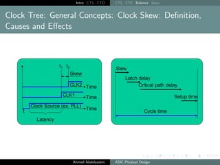
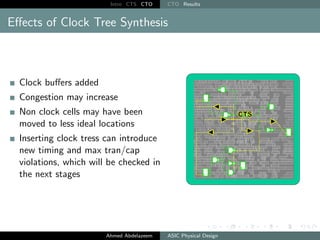
Intro CTS CTO
Clock Tree Synthesis
How to Synchronize your own chip
Ahmed Abdelazeem
Faculty of Engineering
Zagazig University
RTL2GDSII Flow, March 2022
Ahmed Abdelazeem ASIC Physical Design
Intro CTS CTO
Table of Contents
1 Introduction
2 Clock Tree Synthesis
3 Clock Tree Optimization
Ahmed Abdelazeem ASIC Physical Design
Intro CTS CTO CTS CTS Balance Skew
Table of Contents
1 Introduction
2 Clock Tree Synthesis
3 Clock Tree Optimization
Ahmed Abdelazeem ASIC Physical Design
Intro CTS CTO CTS CTS Balance Skew
Design Status, Start of CTS Phase
Placement - completed
Power and ground nets – prerouted
Estimated congestion - acceptable
Estimated timing - acceptable ( 0ns slack)
Estimated max cap/transition – no violations
High fanout nets:
1 Reset, Scan Enable synthesized with buffers
2 Clocks are still not buffered
Question
Why are there no buffers on clock nets?
Ahmed Abdelazeem ASIC Physical Design
Intro CTS CTO CTS CTS Balance Skew
CTS Problem
CTS is the process of distributing clock signals to clock pins
based on physical/layout information
After placement of cells the tree of synchronization is
synthesized
Balanced clock tree is synchronized with the addition of
buffers
After routing CT optimization is made
Ahmed Abdelazeem ASIC Physical Design
Intro CTS CTO CTS CTS Balance Skew
Starting Point before CTS
All clock pins are driven by a single clock source
All clock pins are from a source of clock pulses in various
geometrical distances
Ahmed Abdelazeem ASIC Physical Design
Intro CTS CTO CTS CTS Balance Skew
CTS Goals
Ahmed Abdelazeem ASIC Physical Design
Intro CTS CTO CTS CTS Balance Skew
Clock Tree Synthesis (CTS) (1/2)
Ahmed Abdelazeem ASIC Physical Design
Intro CTS CTO CTS CTS Balance Skew
Clock Tree Synthesis (CTS) (2/2)
Ahmed Abdelazeem ASIC Physical Design
Intro CTS CTO CTS CTS Balance Skew
Clock Tree: General Concepts: Clock Distribution Network
Ahmed Abdelazeem ASIC Physical Design
Intro CTS CTO CTS CTS Balance Skew
Clock Tree: General Concepts: Clock Tree Goal and
Metrics
Goal
Basic connectivity
Metrics
Skew
Power
Area
Slew rates
Ahmed Abdelazeem ASIC Physical Design
Intro CTS CTO CTS CTS Balance Skew
Clock Tree: General Concepts: Clock Skew: Definition,
Causes and Effects
Ahmed Abdelazeem ASIC Physical Design
Intro CTS CTO CTS CTS Balance Skew
Clock Skew Types
Global
Global skew is recommended - fastest
may add unnecessary buffers
Local
Longer runtime
Possibly fewer buffers ” Only related FFs are balanced for skew
”
Useful
Used to fix small violations where local or global failed
Ahmed Abdelazeem ASIC Physical Design
Intro CTS CTO CTS CTS Balance Skew
Global Skew: Fastest Runtime
Ahmed Abdelazeem ASIC Physical Design
Intro CTS CTO CTS CTS Balance Skew
Local Skew: Targeted Synthesis, But Slower
Ahmed Abdelazeem ASIC Physical Design
Intro CTS CTO CTS CTS Balance Skew
Useful Skew
Ahmed Abdelazeem ASIC Physical Design
Intro CTS CTO CTS Targets Cons Control NDR
Table of Contents
1 Introduction
2 Clock Tree Synthesis
3 Clock Tree Optimization
Ahmed Abdelazeem ASIC Physical Design
Intro CTS CTO CTS Targets Cons Control NDR
Clock Tree Synthesis
Ahmed Abdelazeem ASIC Physical Design
Intro CTS CTO CTS Targets Cons Control NDR
Clock Tree Synthesis
Ahmed Abdelazeem ASIC Physical Design
Intro CTS CTO CTS Targets Cons Control NDR
Understand Your Clock Tree Goals
Skew Goal
What are the skew requirements for your design?
Are there different skew targets for small and large clocks?
Insertion Delay Goal
What are the insertion delay specs for your block?
What is a reasonable target based on the size and floorplan of
your block/chip?
Nondefault rules to prevent SI problems
DRC Requirements
Are signal net DRCs different from clock net DRCs?
Find out the order of significance or importance of all
the clocks in the design
Ahmed Abdelazeem ASIC Physical Design
Intro CTS CTO CTS Targets Cons Control NDR
Default Clock Tree Targets
The default CTS target for skew and insertion delay is
Ons
Uncertainty and insertion delay SDC constraints are ignored
It is recommended to relax the clock skew target as
much as possible
Reduces overall buffer count, Power, and run time
Specify minimum clock latencies as needed
Ahmed Abdelazeem ASIC Physical Design
Intro CTS CTO CTS Targets Cons Control NDR
Constraints: Are all Clock Drivers and Loads Specified?
Ahmed Abdelazeem ASIC Physical Design
Intro CTS CTO CTS Targets Cons Control NDR
Where Does the Clock Tree Begin and End?
Ahmed Abdelazeem ASIC Physical Design
Intro CTS CTO CTS Targets Cons Control NDR
Define Clock Root Attributes (1/2)
When the clock root is a primary port of a block
Ensure that an appropriate driving cell is defined
set driving cell
The synthesis constraints may include a weak driving cell for
all inputs, including the clock port
Because the clock is ideal during synthesis it has no effect on
design QoR
But a weak driver on the clock port affects clock tree QoR
during CTS
Ahmed Abdelazeem ASIC Physical Design
Intro CTS CTO CTS Targets Cons Control NDR
Define Clock Root Attributes (2/2)
When the clock root is a primary port, but at the
CHIP-level through an IO-PAD
Ensure that an appropriate input transition is defined
set input transition
Ahmed Abdelazeem ASIC Physical Design
Intro CTS CTO CTS Targets Cons Control NDR
Stop, Float and Exclude Pins
Stop Pins:
CTS optimizes for DRC and
clock tree targets (skew, insertion
delay)
Float Pins:
Like Stop pins, but with delays
on clock pin
Exclude (Ignore) Pins:
CTS ignores skew and insertion
delay targets
CTS will fix DRCs to meet library
or SDC constraints
Ahmed Abdelazeem ASIC Physical Design
Intro CTS CTO CTS Targets Cons Control NDR
Generated and Gated Clocks
Ahmed Abdelazeem ASIC Physical Design
Intro CTS CTO CTS Targets Cons Control NDR
Skew Balancing not Required
Ahmed Abdelazeem ASIC Physical Design
Intro CTS CTO CTS Targets Cons Control NDR
No Inter-Clock Skew Balancing by Default
Ahmed Abdelazeem ASIC Physical Design
Intro CTS CTO CTS Targets Cons Control NDR
Inter-Clock Delay Balancing
Ahmed Abdelazeem ASIC Physical Design
Intro CTS CTO CTS Targets Cons Control NDR
Inter-Clock Delay Balancing: With Offset
Ahmed Abdelazeem ASIC Physical Design
Intro CTS CTO CTS Targets Cons Control NDR
User-defined or Explicit Stop Pins
Ahmed Abdelazeem ASIC Physical Design
Intro CTS CTO CTS Targets Cons Control NDR
Defining an Explicit Stop Pin
Ahmed Abdelazeem ASIC Physical Design
Intro CTS CTO CTS Targets Cons Control NDR
Defining an Explicit Float Pin
Ahmed Abdelazeem ASIC Physical Design
Intro CTS CTO CTS Targets Cons Control NDR
Non-Default Clock Routing
PnR Tool can route the clocks using non-default routing rules,
e.g. double-spacing, double-width, shielding, and double via
Non-default rules are often used to “harden” the clock, e.g.
to make the clock routes less sensitive to Cross Talk or EM
effects, which improve yield
Ahmed Abdelazeem ASIC Physical Design
Intro CTS CTO CTS Targets Cons Control NDR
NDR Recommendations
Always route clock on metal 3 and above
Avoid NDR on Metal 1
may have trouble accessing metal 1 pins on buffers and gates
Consider using double spacing to reduce crosstalk
Consider double width to reduce resistance
Consider double via to reduce resistance and improve
yield
Ahmed Abdelazeem ASIC Physical Design
Intro CTS CTO CTS Targets Cons Control NDR
Put NDR on Pitch for Accurate RC Estimation
Metal traces are always routed “on pitch”
With clock NDR rules, pre-routing RC estimates of
clock nets use NDR width and spacing numbers
If NDR [spacing + width] numbers are not integer
multiples of pitch (i.e. off-pitch), timing estimates
pre-route may not correlate well with post-route timing
Make sure your NDR numbers are on pitch!
Ahmed Abdelazeem ASIC Physical Design
Intro CTS CTO CTO Results
Table of Contents
1 Introduction
2 Clock Tree Synthesis
3 Clock Tree Optimization
Ahmed Abdelazeem ASIC Physical Design
Intro CTS CTO CTO Results
Clock Tree Optimization
Perform additional Clock Tree Optimization as necessary to
further improve clock skew.
Ahmed Abdelazeem ASIC Physical Design
Intro CTS CTO CTO Results
Clock Tree Optimization Options
Ahmed Abdelazeem ASIC Physical Design
Intro CTS CTO CTO Results
Analyzing CTS Results
Report clock tree
Summary
Settings
. . .
Reports max global skew, late/early insertion delay, number of
levels in clock tree, number of clock tree references (buffers),
clock DRC violations
Report clock timing
Reports actual, relevant skew, latency, interclock latency etc.
for paths that are related
Ahmed Abdelazeem ASIC Physical Design
Intro CTS CTO CTO Results
Effects of Clock Tree Synthesis
Clock buffers added
Congestion may increase
Non clock cells may have been
moved to less ideal locations
Inserting clock tress can introduce
new timing and max tran/cap
violations, which will be checked in
the next stages
Ahmed Abdelazeem ASIC Physical Design
Intro CTS CTO CTO Results
....
ÕækQË@ áÔgQË@ éÊË@ Õæ„.
C

JÊ
¯ B

@ Õ

Ϊ

Ë@ áÓ Õ
æJKð@ AÓð
Ahmed Abdelazeem ASIC Physical Design

Clock Tree Synthesis.pdf

  • 1.
    Intro CTS CTO ClockTree Synthesis How to Synchronize your own chip Ahmed Abdelazeem Faculty of Engineering Zagazig University RTL2GDSII Flow, March 2022 Ahmed Abdelazeem ASIC Physical Design
  • 2.
    Intro CTS CTO Tableof Contents 1 Introduction 2 Clock Tree Synthesis 3 Clock Tree Optimization Ahmed Abdelazeem ASIC Physical Design
  • 3.
    Intro CTS CTOCTS CTS Balance Skew Table of Contents 1 Introduction 2 Clock Tree Synthesis 3 Clock Tree Optimization Ahmed Abdelazeem ASIC Physical Design
  • 4.
    Intro CTS CTOCTS CTS Balance Skew Design Status, Start of CTS Phase Placement - completed Power and ground nets – prerouted Estimated congestion - acceptable Estimated timing - acceptable ( 0ns slack) Estimated max cap/transition – no violations High fanout nets: 1 Reset, Scan Enable synthesized with buffers 2 Clocks are still not buffered Ahmed Abdelazeem ASIC Physical Design
  • 5.
    Intro CTS CTOCTS CTS Balance Skew Design Status, Start of CTS Phase Placement - completed Power and ground nets – prerouted Estimated congestion - acceptable Estimated timing - acceptable ( 0ns slack) Estimated max cap/transition – no violations High fanout nets: 1 Reset, Scan Enable synthesized with buffers 2 Clocks are still not buffered Question Why are there no buffers on clock nets? Ahmed Abdelazeem ASIC Physical Design
  • 6.
    Intro CTS CTOCTS CTS Balance Skew CTS Problem CTS is the process of distributing clock signals to clock pins based on physical/layout information After placement of cells the tree of synchronization is synthesized Balanced clock tree is synchronized with the addition of buffers After routing CT optimization is made Ahmed Abdelazeem ASIC Physical Design
  • 7.
    Intro CTS CTOCTS CTS Balance Skew Starting Point before CTS All clock pins are driven by a single clock source All clock pins are from a source of clock pulses in various geometrical distances Ahmed Abdelazeem ASIC Physical Design
  • 8.
    Intro CTS CTOCTS CTS Balance Skew CTS Goals Ahmed Abdelazeem ASIC Physical Design
  • 9.
    Intro CTS CTOCTS CTS Balance Skew Clock Tree Synthesis (CTS) (1/2) Ahmed Abdelazeem ASIC Physical Design
  • 10.
    Intro CTS CTOCTS CTS Balance Skew Clock Tree Synthesis (CTS) (2/2) Ahmed Abdelazeem ASIC Physical Design
  • 11.
    Intro CTS CTOCTS CTS Balance Skew Clock Tree: General Concepts: Clock Distribution Network Ahmed Abdelazeem ASIC Physical Design
  • 12.
    Intro CTS CTOCTS CTS Balance Skew Clock Tree: General Concepts: Clock Tree Goal and Metrics Goal Basic connectivity Metrics Skew Power Area Slew rates Ahmed Abdelazeem ASIC Physical Design
  • 13.
    Intro CTS CTOCTS CTS Balance Skew Clock Tree: General Concepts: Clock Skew: Definition, Causes and Effects Ahmed Abdelazeem ASIC Physical Design
  • 14.
    Intro CTS CTOCTS CTS Balance Skew Clock Skew Types Global Global skew is recommended - fastest may add unnecessary buffers Local Longer runtime Possibly fewer buffers ” Only related FFs are balanced for skew ” Useful Used to fix small violations where local or global failed Ahmed Abdelazeem ASIC Physical Design
  • 15.
    Intro CTS CTOCTS CTS Balance Skew Global Skew: Fastest Runtime Ahmed Abdelazeem ASIC Physical Design
  • 16.
    Intro CTS CTOCTS CTS Balance Skew Local Skew: Targeted Synthesis, But Slower Ahmed Abdelazeem ASIC Physical Design
  • 17.
    Intro CTS CTOCTS CTS Balance Skew Useful Skew Ahmed Abdelazeem ASIC Physical Design
  • 18.
    Intro CTS CTOCTS Targets Cons Control NDR Table of Contents 1 Introduction 2 Clock Tree Synthesis 3 Clock Tree Optimization Ahmed Abdelazeem ASIC Physical Design
  • 19.
    Intro CTS CTOCTS Targets Cons Control NDR Clock Tree Synthesis Ahmed Abdelazeem ASIC Physical Design
  • 20.
    Intro CTS CTOCTS Targets Cons Control NDR Clock Tree Synthesis Ahmed Abdelazeem ASIC Physical Design
  • 21.
    Intro CTS CTOCTS Targets Cons Control NDR Understand Your Clock Tree Goals Skew Goal What are the skew requirements for your design? Are there different skew targets for small and large clocks? Insertion Delay Goal What are the insertion delay specs for your block? What is a reasonable target based on the size and floorplan of your block/chip? Nondefault rules to prevent SI problems DRC Requirements Are signal net DRCs different from clock net DRCs? Find out the order of significance or importance of all the clocks in the design Ahmed Abdelazeem ASIC Physical Design
  • 22.
    Intro CTS CTOCTS Targets Cons Control NDR Default Clock Tree Targets The default CTS target for skew and insertion delay is Ons Uncertainty and insertion delay SDC constraints are ignored It is recommended to relax the clock skew target as much as possible Reduces overall buffer count, Power, and run time Specify minimum clock latencies as needed Ahmed Abdelazeem ASIC Physical Design
  • 23.
    Intro CTS CTOCTS Targets Cons Control NDR Constraints: Are all Clock Drivers and Loads Specified? Ahmed Abdelazeem ASIC Physical Design
  • 24.
    Intro CTS CTOCTS Targets Cons Control NDR Where Does the Clock Tree Begin and End? Ahmed Abdelazeem ASIC Physical Design
  • 25.
    Intro CTS CTOCTS Targets Cons Control NDR Define Clock Root Attributes (1/2) When the clock root is a primary port of a block Ensure that an appropriate driving cell is defined set driving cell The synthesis constraints may include a weak driving cell for all inputs, including the clock port Because the clock is ideal during synthesis it has no effect on design QoR But a weak driver on the clock port affects clock tree QoR during CTS Ahmed Abdelazeem ASIC Physical Design
  • 26.
    Intro CTS CTOCTS Targets Cons Control NDR Define Clock Root Attributes (2/2) When the clock root is a primary port, but at the CHIP-level through an IO-PAD Ensure that an appropriate input transition is defined set input transition Ahmed Abdelazeem ASIC Physical Design
  • 27.
    Intro CTS CTOCTS Targets Cons Control NDR Stop, Float and Exclude Pins Stop Pins: CTS optimizes for DRC and clock tree targets (skew, insertion delay) Float Pins: Like Stop pins, but with delays on clock pin Exclude (Ignore) Pins: CTS ignores skew and insertion delay targets CTS will fix DRCs to meet library or SDC constraints Ahmed Abdelazeem ASIC Physical Design
  • 28.
    Intro CTS CTOCTS Targets Cons Control NDR Generated and Gated Clocks Ahmed Abdelazeem ASIC Physical Design
  • 29.
    Intro CTS CTOCTS Targets Cons Control NDR Skew Balancing not Required Ahmed Abdelazeem ASIC Physical Design
  • 30.
    Intro CTS CTOCTS Targets Cons Control NDR No Inter-Clock Skew Balancing by Default Ahmed Abdelazeem ASIC Physical Design
  • 31.
    Intro CTS CTOCTS Targets Cons Control NDR Inter-Clock Delay Balancing Ahmed Abdelazeem ASIC Physical Design
  • 32.
    Intro CTS CTOCTS Targets Cons Control NDR Inter-Clock Delay Balancing: With Offset Ahmed Abdelazeem ASIC Physical Design
  • 33.
    Intro CTS CTOCTS Targets Cons Control NDR User-defined or Explicit Stop Pins Ahmed Abdelazeem ASIC Physical Design
  • 34.
    Intro CTS CTOCTS Targets Cons Control NDR Defining an Explicit Stop Pin Ahmed Abdelazeem ASIC Physical Design
  • 35.
    Intro CTS CTOCTS Targets Cons Control NDR Defining an Explicit Float Pin Ahmed Abdelazeem ASIC Physical Design
  • 36.
    Intro CTS CTOCTS Targets Cons Control NDR Non-Default Clock Routing PnR Tool can route the clocks using non-default routing rules, e.g. double-spacing, double-width, shielding, and double via Non-default rules are often used to “harden” the clock, e.g. to make the clock routes less sensitive to Cross Talk or EM effects, which improve yield Ahmed Abdelazeem ASIC Physical Design
  • 37.
    Intro CTS CTOCTS Targets Cons Control NDR NDR Recommendations Always route clock on metal 3 and above Avoid NDR on Metal 1 may have trouble accessing metal 1 pins on buffers and gates Consider using double spacing to reduce crosstalk Consider double width to reduce resistance Consider double via to reduce resistance and improve yield Ahmed Abdelazeem ASIC Physical Design
  • 38.
    Intro CTS CTOCTS Targets Cons Control NDR Put NDR on Pitch for Accurate RC Estimation Metal traces are always routed “on pitch” With clock NDR rules, pre-routing RC estimates of clock nets use NDR width and spacing numbers If NDR [spacing + width] numbers are not integer multiples of pitch (i.e. off-pitch), timing estimates pre-route may not correlate well with post-route timing Make sure your NDR numbers are on pitch! Ahmed Abdelazeem ASIC Physical Design
  • 39.
    Intro CTS CTOCTO Results Table of Contents 1 Introduction 2 Clock Tree Synthesis 3 Clock Tree Optimization Ahmed Abdelazeem ASIC Physical Design
  • 40.
    Intro CTS CTOCTO Results Clock Tree Optimization Perform additional Clock Tree Optimization as necessary to further improve clock skew. Ahmed Abdelazeem ASIC Physical Design
  • 41.
    Intro CTS CTOCTO Results Clock Tree Optimization Options Ahmed Abdelazeem ASIC Physical Design
  • 42.
    Intro CTS CTOCTO Results Analyzing CTS Results Report clock tree Summary Settings . . . Reports max global skew, late/early insertion delay, number of levels in clock tree, number of clock tree references (buffers), clock DRC violations Report clock timing Reports actual, relevant skew, latency, interclock latency etc. for paths that are related Ahmed Abdelazeem ASIC Physical Design
  • 43.
    Intro CTS CTOCTO Results Effects of Clock Tree Synthesis Clock buffers added Congestion may increase Non clock cells may have been moved to less ideal locations Inserting clock tress can introduce new timing and max tran/cap violations, which will be checked in the next stages Ahmed Abdelazeem ASIC Physical Design
  • 44.
    Intro CTS CTOCTO Results .... ÕækQË@ áÔgQË@ éÊË@ Õæ„. C JÊ ¯ B @ Õ Îª Ë@ áÓ Õ æJKð@ AÓð Ahmed Abdelazeem ASIC Physical Design