Downloaded 145 times
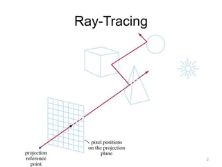


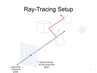

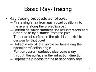
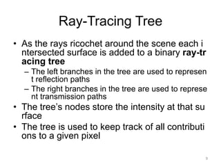
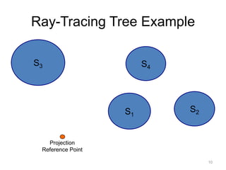


Ray tracing is a technique for generating images by tracing the path of light through pixels and simulating interactions with virtual objects. It can produce highly realistic images but is computationally expensive. Ray tracing works by firing rays from the eye position through each pixel into the scene, determining the nearest intersected surface, then recursively firing reflection and refraction rays to calculate each surface's contribution to pixel color. Ray intersections are organized into a tree structure to track color contributions to each pixel. At each intersection, illumination models calculate surface color based on factors like normal, light direction, and whether shadow rays to lights are blocked.