
![Object Intersections
● Basic geometry - sphere and some others here
● Ray is a vector R(t) = R0 + t.Rd (R0 origin, Rd direction)
● Sphere S set of points where (xs - xc)2 + (ys - yc)2 + (zs - zc)2 = Sr2
● Substituting: (X0 + Xd.t - Xc)2 + (Y0 + Yd.t - Yc)2 + (Z0 + Zd.t - Zc)2 = Sr2
● Quadratic of form At2 + Bt + C = 0 (if |Rd| = 1, A == 1) so
● A = 1, B = 2.(Xd.(X0 - Xc) + Yd.(Y0 - Yc) + Zd.(Z0 - Zc))}
C = (X0 - Xc)2 + (Y0 - Yc)2 + (Z0 - Zc)2 - Sr2
● Intersections t0, t1 = (- B ∓ (B2 - 4C)½) / 2
● If Discriminant < 0 (B2 - 4C) - no intersection, else t0 > 0 ? t0 : t1
● Point of intersection Ri = [xi, yi, zi] = [x0 + xd.ti , y0 + yd.ti, z0 +
zd.ti]
● Surface normal Sn = [(xi - xc)/Sr, (yi - yc)/Sr, (zi -](https://image.slidesharecdn.com/17-190226165611/85/Green-Custard-Friday-Talk-17-Ray-Tracing-7-320.jpg)


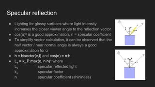
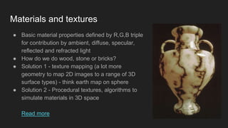
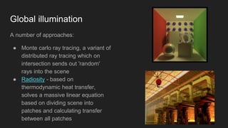

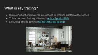
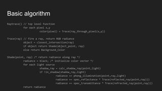
The document outlines the principles of ray tracing, a technique for simulating light and material interactions to create photorealistic images. It describes the algorithms involved, including tracing rays from the camera through the scene and calculating reflections, shadows, and illumination from various light sources. Additionally, it touches on material textures, anti-aliasing, and approaches for global illumination, highlighting methods to speed up the rendering process.