Downloaded 34 times
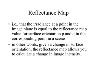
![Use of Specularities and Motion in the Extraction of Surface Shape Damian Gordon [email_address]](https://image.slidesharecdn.com/seminar2-110104184703-phpapp01/85/Computer-Vision-Shape-from-Specularities-and-Motion-1-320.jpg)
![Use of Specularities and Motion in the Extraction of Surface Shape Damian Gordon [email_address]](https://image.slidesharecdn.com/seminar2-110104184703-phpapp01/75/Computer-Vision-Shape-from-Specularities-and-Motion-1-2048.jpg)

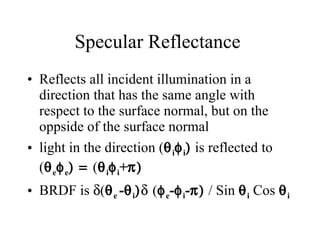
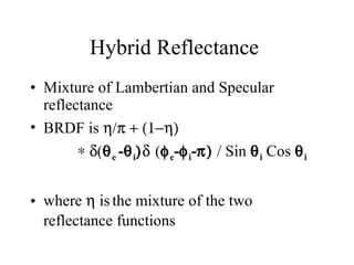
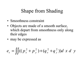


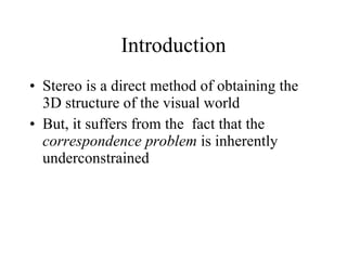
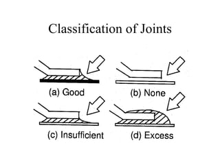
![Hybrid Reflectance The reflectance relationship for a hybrid model of image E(x,y) E(x,y) = A k (n . s) + (a/2)(1-k) . [2(n . z)(n . s)-(z . s)] z = viewing direction (unit vector) k = relative weight of specular and Lambertian components n = sharpness of the specularity](https://image.slidesharecdn.com/seminar2-110104184703-phpapp01/85/Computer-Vision-Shape-from-Specularities-and-Motion-46-320.jpg)
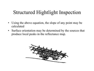
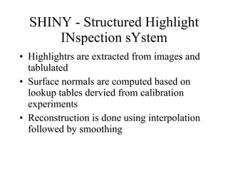
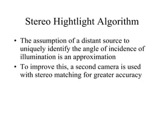

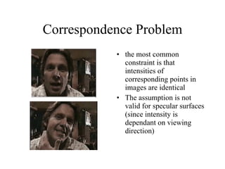
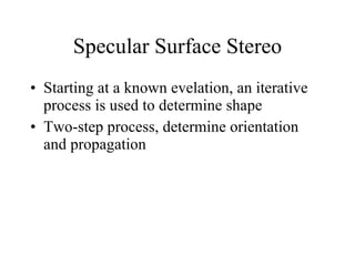
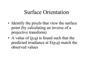
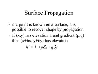
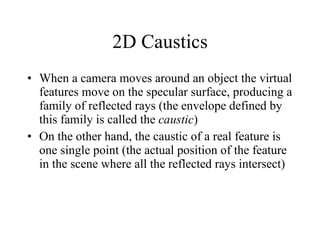
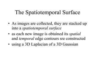
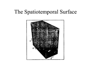
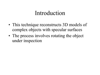
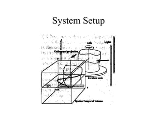


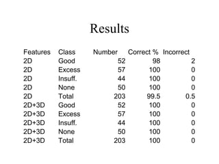
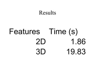

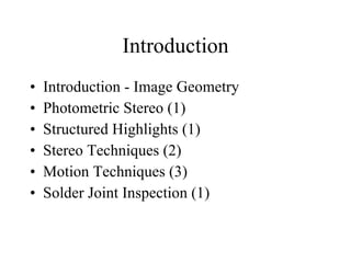
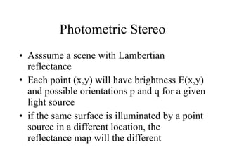
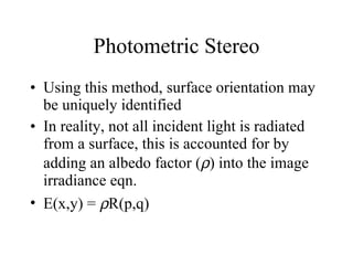
The document discusses using specularities and motion to extract surface shape from images. Specifically, it discusses using: 1) Structured highlights from a spherical array of light sources to determine surface orientation of specular surfaces from the detected highlights. 2) Photometric stereo with multiple light source positions to determine surface orientation of both diffuse and specular surfaces. 3) Stereo techniques using highlights detected from multiple camera views to reconstruct the 3D shape of specular surfaces.


