10/9/201
3
1
OVERVIEW OF RAY TRACING.
INTERSECTING RAYS WITH OTHER PRIMITIVES.
10/9/201
3
2
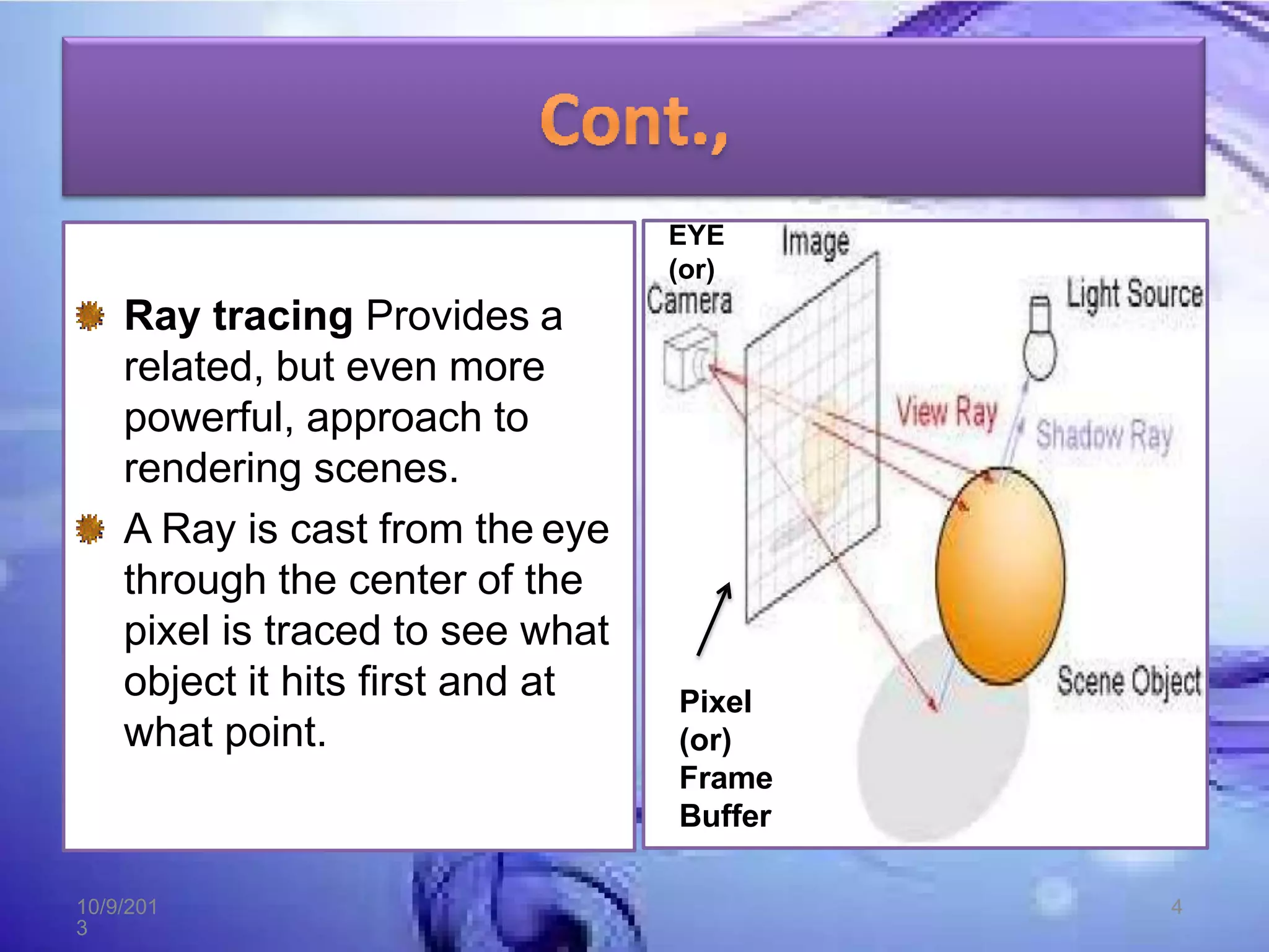
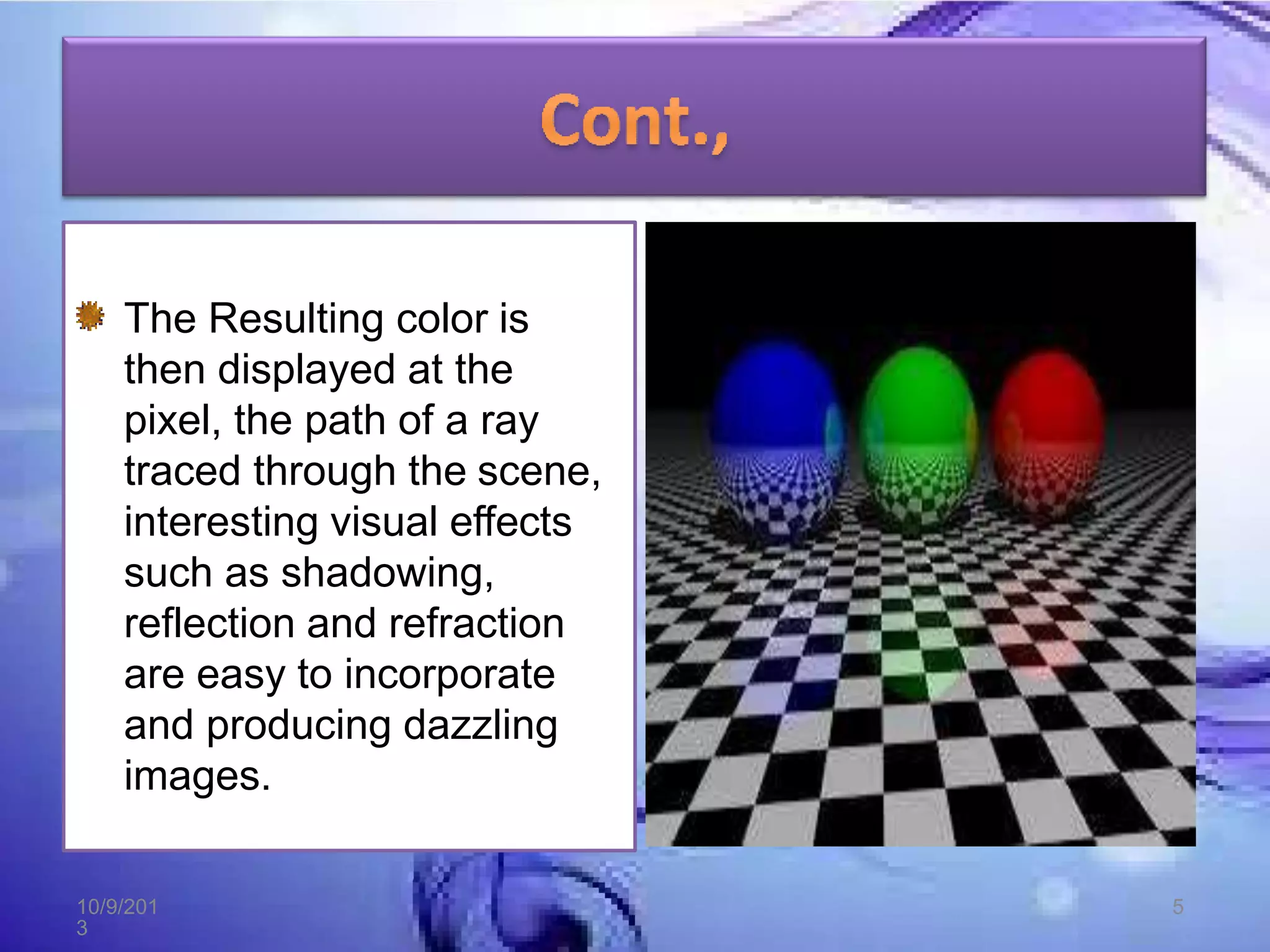
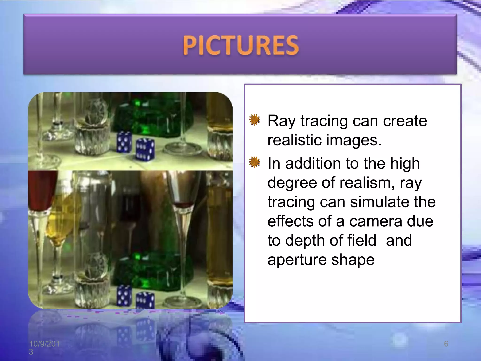
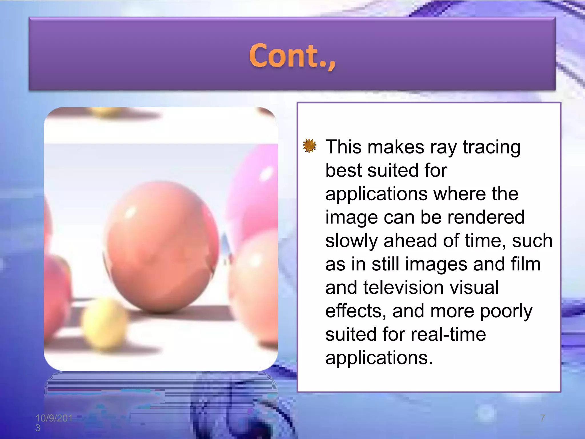
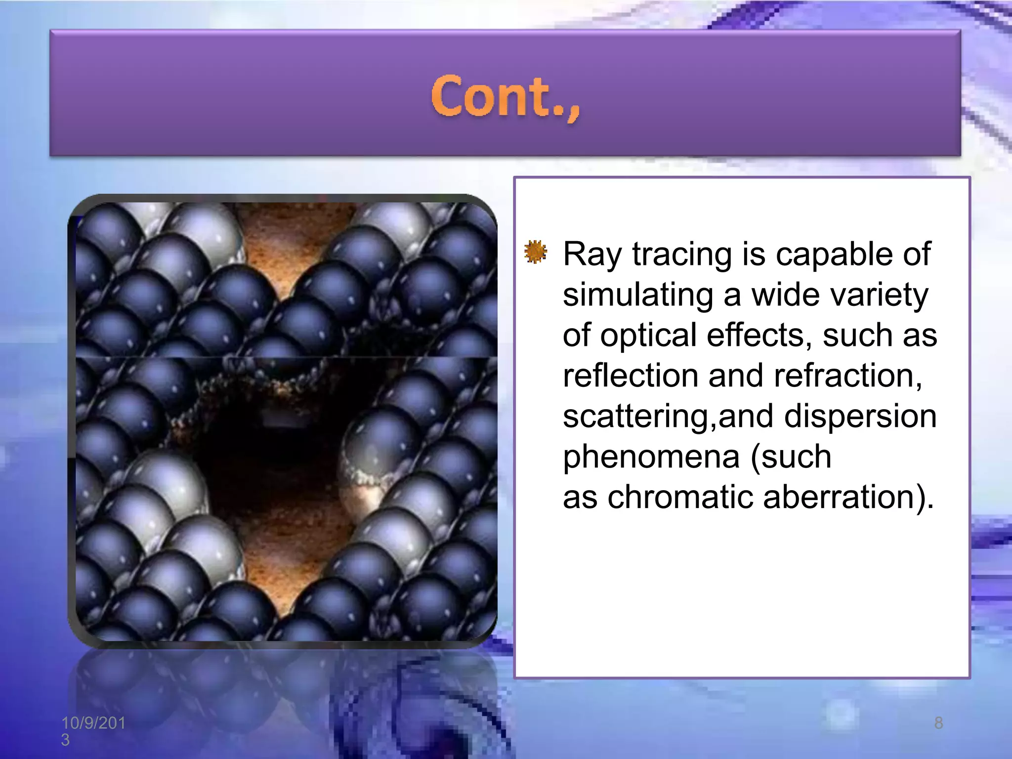
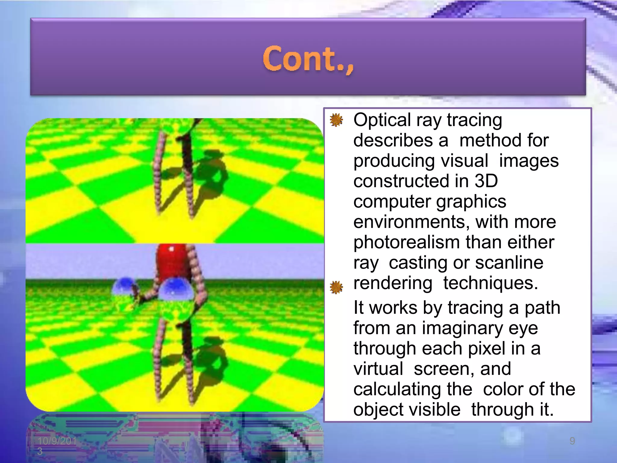
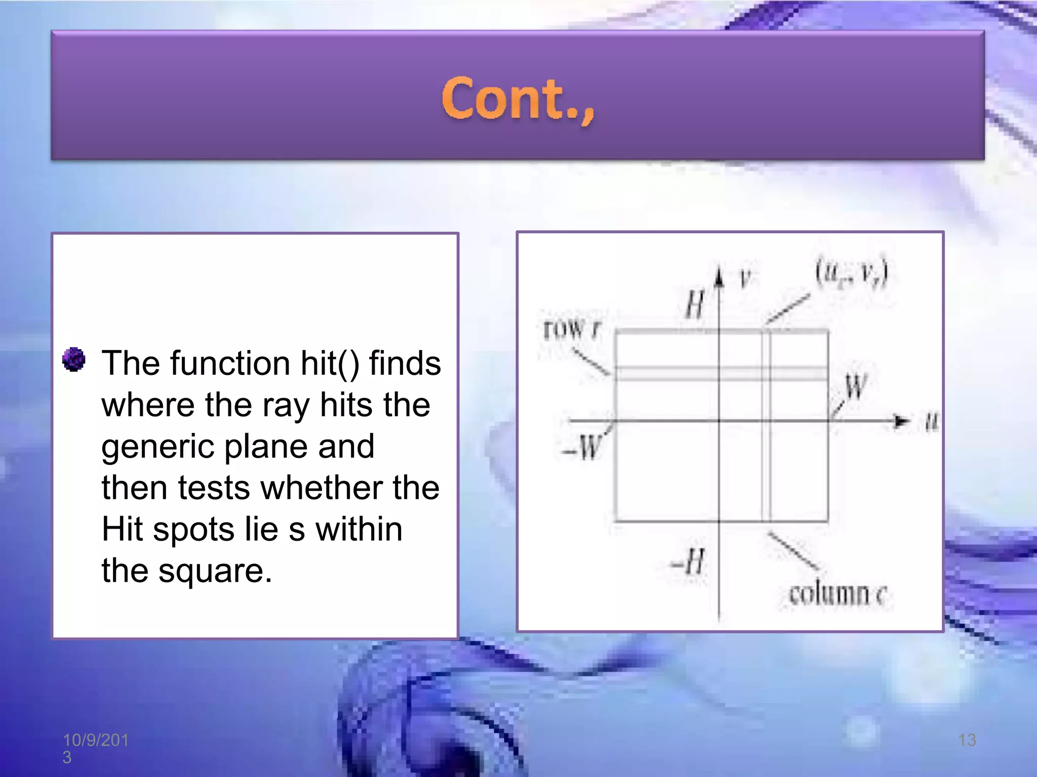
Ray tracing is a technique for generating an image by
tracing the path of light through pixels in an image
plane and simulating the effects of its encounters with
virtual objects.
The technique is capable of producing a very high
degree of visual realism, usually higher than that of
typical scan line rendering methods, but at a
greater computational cost.
10/9/201
3
3
Ray tracing Provides a
related, but even more
powerful, approach to
rendering scenes.
A Ray is cast from the eye
through the center of the
pixel is traced to see what
object it hits first and at
what point.
EYE
(or)
Pixel
(or)
Frame
Buffer
10/9/201
3
4
The Resulting color is
then displayed at the
pixel, the path of a ray
traced through the scene,
interesting visual effects
such as shadowing,
reflection and refraction
are easy to incorporate
and producing dazzling
images.
10/9/201
3
5
Ray tracing can create
realistic images.
In addition to the high
degree of realism, ray
tracing can simulate the
effects of a camera due
to depth of field and
aperture shape
10/9/201
3
6
This makes ray tracing
best suited for
applications where the
image can be rendered
slowly ahead of time, such
as in still images and film
and television visual
effects, and more poorly
suited for real-time
applications.
10/9/201
3
7
Ray tracing is capable of
simulating a wide variety
of optical effects, such as
reflection and refraction,
scattering,and dispersion
phenomena (such
as chromatic aberration).
10/9/201
3
8
Optical ray tracing
describes a method for
producing visual images
constructed in 3D
computer graphics
environments, with more
photorealism than either
ray casting or scanline
rendering techniques.
It works by tracing a path
from an imaginary eye
through each pixel in a
virtual screen, and
calculating the color of the
object visible through it.
10/9/201
3
9
Descriptions of all then
Objects are stored in an
object list.
The ray that interacts the
Sphere and the Cylinder.
The hit spot (PHIT) is
easily
found wit the ray itself.
The ray of Equation at the
Hit time tbit :
PHIT=eye + dirr,ctbit
EYE
(or)
Pixel
(or)
Frame
Buffer
PHI
T
10/9/201
3
10
define the objects and light sources in the scene set up the camera
for(int r=0 ; r < nRows ; r++)
for(int c=0 ; c < nCols ; c++)
{
1.Build the rc-th ray.
2.Find all interactions of the rc-th ray with objects in the scene.
3.Identify the intersection that lies closest to and infront of the eye.
4.Compute the Hit Point.
5.Find the color of the light returning to the eye along the ray from
the point of intersection.
6.Place the color in the rc-th pixel.
}
10/9/201
3
11
We need to Develop the hit() method for other shape
classes.
Intersecting with a square:
A square is useful generic shape.
The generic square lies in the z=0 plane and extends
from -1 to +1 in both x and y axis.
The implicit form of the equation of the square is
F(P)=PZ for |PX| <= 1 and |PY| <= 1.
The Square can be transformed into any parallelogram
positioned in space & provide thin, flat surface like Walls,
Windows, etc.
10/9/201
3
12
The function hit() finds
where the ray hits the
generic plane and
then tests whether the
Hit spots lie s within
the square.
10/9/201
3
13
Intersecting with a Cube or any Convex Polyhedron:
Convex Polyhedron is useful in many graphics
situations.
It is centered at the origin and has corners, using all six
combinations of +1 and -1.
The edges are aligned with the coordinate axes, and its
six faces lie in the Planes.
10/9/201
3
14
PLANE NAME EQUATION OUTWARD
NORMAL
SPOT
0 TOP Y=1 (0,1,0) (0,1,0)
1 BOTTOM Y=-1 (0,-1,0) (0,-1,0)
2 RIGHT X=1 (1,0,0) (1,0,0)
3 LEFT X=-1 (-1,0,0) (-1,0,0)
4 FRONT Z=1 (0,0,0) (0,0,0)
5 BACK Z=-1 (0,0,-1) (0,0,-1)
10/9/201
3
15
10/9/201
3
16
The generic cube is important for 2 reasons:
1. A Large variety of interesting โ€œboxesโ€ can be Modeled
and Placed in a scene by applying an affine
transformation to a generic cube. In Ray Tracing each
ray can be inverse transformed into the generic cubeโ€™s
coordinate system.
2. The generic cube can be used as an extent for the other
geometric primitives in the sense of a Bounding box.
10/9/201
3
17
10/9/201
3
18

Ray tracing converted (1)

  • 1.
  • 2.
    OVERVIEW OF RAYTRACING. INTERSECTING RAYS WITH OTHER PRIMITIVES. 10/9/201 3 2
  • 3.
    Ray tracing isa technique for generating an image by tracing the path of light through pixels in an image plane and simulating the effects of its encounters with virtual objects. The technique is capable of producing a very high degree of visual realism, usually higher than that of typical scan line rendering methods, but at a greater computational cost. 10/9/201 3 3
  • 4.
    Ray tracing Providesa related, but even more powerful, approach to rendering scenes. A Ray is cast from the eye through the center of the pixel is traced to see what object it hits first and at what point. EYE (or) Pixel (or) Frame Buffer 10/9/201 3 4
  • 5.
    The Resulting coloris then displayed at the pixel, the path of a ray traced through the scene, interesting visual effects such as shadowing, reflection and refraction are easy to incorporate and producing dazzling images. 10/9/201 3 5
  • 6.
    Ray tracing cancreate realistic images. In addition to the high degree of realism, ray tracing can simulate the effects of a camera due to depth of field and aperture shape 10/9/201 3 6
  • 7.
    This makes raytracing best suited for applications where the image can be rendered slowly ahead of time, such as in still images and film and television visual effects, and more poorly suited for real-time applications. 10/9/201 3 7
  • 8.
    Ray tracing iscapable of simulating a wide variety of optical effects, such as reflection and refraction, scattering,and dispersion phenomena (such as chromatic aberration). 10/9/201 3 8
  • 9.
    Optical ray tracing describesa method for producing visual images constructed in 3D computer graphics environments, with more photorealism than either ray casting or scanline rendering techniques. It works by tracing a path from an imaginary eye through each pixel in a virtual screen, and calculating the color of the object visible through it. 10/9/201 3 9
  • 10.
    Descriptions of allthen Objects are stored in an object list. The ray that interacts the Sphere and the Cylinder. The hit spot (PHIT) is easily found wit the ray itself. The ray of Equation at the Hit time tbit : PHIT=eye + dirr,ctbit EYE (or) Pixel (or) Frame Buffer PHI T 10/9/201 3 10
  • 11.
    define the objectsand light sources in the scene set up the camera for(int r=0 ; r < nRows ; r++) for(int c=0 ; c < nCols ; c++) { 1.Build the rc-th ray. 2.Find all interactions of the rc-th ray with objects in the scene. 3.Identify the intersection that lies closest to and infront of the eye. 4.Compute the Hit Point. 5.Find the color of the light returning to the eye along the ray from the point of intersection. 6.Place the color in the rc-th pixel. } 10/9/201 3 11
  • 12.
    We need toDevelop the hit() method for other shape classes. Intersecting with a square: A square is useful generic shape. The generic square lies in the z=0 plane and extends from -1 to +1 in both x and y axis. The implicit form of the equation of the square is F(P)=PZ for |PX| <= 1 and |PY| <= 1. The Square can be transformed into any parallelogram positioned in space & provide thin, flat surface like Walls, Windows, etc. 10/9/201 3 12
  • 13.
    The function hit()finds where the ray hits the generic plane and then tests whether the Hit spots lie s within the square. 10/9/201 3 13
  • 14.
    Intersecting with aCube or any Convex Polyhedron: Convex Polyhedron is useful in many graphics situations. It is centered at the origin and has corners, using all six combinations of +1 and -1. The edges are aligned with the coordinate axes, and its six faces lie in the Planes. 10/9/201 3 14
  • 15.
    PLANE NAME EQUATIONOUTWARD NORMAL SPOT 0 TOP Y=1 (0,1,0) (0,1,0) 1 BOTTOM Y=-1 (0,-1,0) (0,-1,0) 2 RIGHT X=1 (1,0,0) (1,0,0) 3 LEFT X=-1 (-1,0,0) (-1,0,0) 4 FRONT Z=1 (0,0,0) (0,0,0) 5 BACK Z=-1 (0,0,-1) (0,0,-1) 10/9/201 3 15
  • 16.
  • 17.
    The generic cubeis important for 2 reasons: 1. A Large variety of interesting โ€œboxesโ€ can be Modeled and Placed in a scene by applying an affine transformation to a generic cube. In Ray Tracing each ray can be inverse transformed into the generic cubeโ€™s coordinate system. 2. The generic cube can be used as an extent for the other geometric primitives in the sense of a Bounding box. 10/9/201 3 17
  • 18.