Download to read offline

![3/20/2018
13
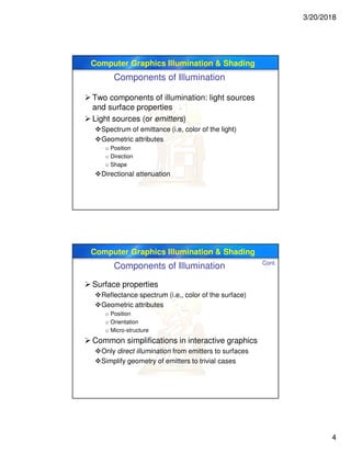
Computer Graphics Illumination & Shading
void InitLights (void)
{
glEnable(GL_LIGHTING); // Turn on the power
glEnable(GL_LIGHT0); // Flip each light’s switch
glEnable(GL_LIGHT1);
GLfloat lightpos0[] = {.5, 1, .5, 0};
glLightfv(GL_LIGHT0, GL_POSITION, lightpos0);
GLfloat lightpos1[] = {4,4,4,0};
glLightfv(GL_LIGHT1, GL_POSITION, lightpos1);
}
Cont.
OpenGL Lighting
Computer Graphics Illumination & Shading
OpenGL Moving Light Source
Light sources transform like geometry
Only modelview transform is applied
Stationary light
Set transform to identity before specifying location
Moving light
push matrix, move light, pop matrix to uniquely control a light’s position
Light source attached to camera](https://image.slidesharecdn.com/7-illuminationandshading-200816192045/85/7-illumination-and-shading-computer-graphics-13-320.jpg)
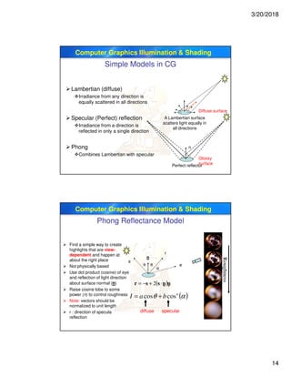
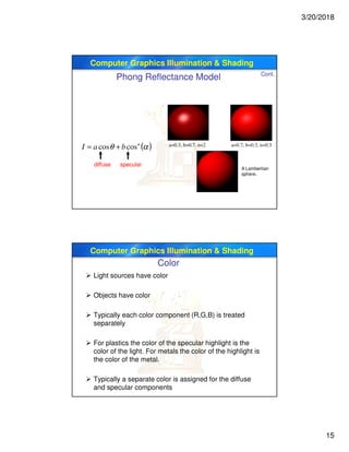
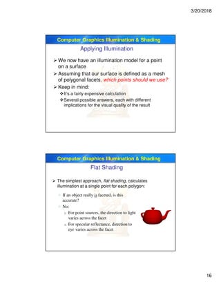
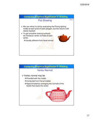


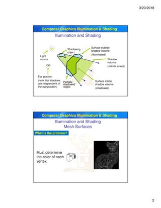
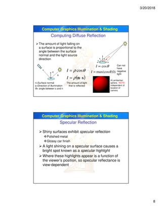
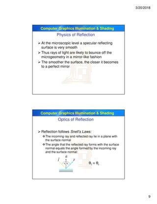
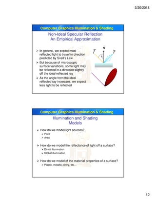
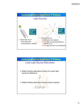
This document discusses illumination and shading in computer graphics. It defines key terms like illumination, lighting, and shading. It describes different types of light sources like ambient, directional, and point lights. It explains the physics of reflection including diffuse and specular reflection. It also discusses empirical and physically-based illumination models as well as the Phong reflectance model.