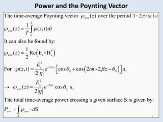
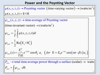
The document discusses electromagnetic wave propagation, focusing on energy transport via EM waves and the mathematical principles governing this, particularly through Maxwell's equations. It introduces the concept of the Poynting vector to describe power flow and details phenomena such as plane wave reflection at material boundaries, including reflection and transmission coefficients. The text provides examples to illustrate these concepts in different media.
![35
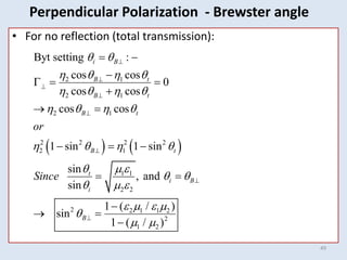
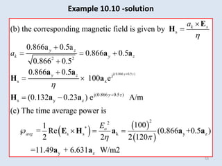
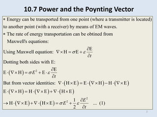
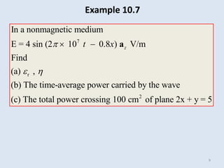
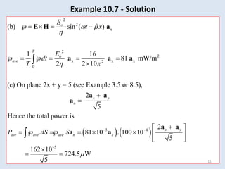
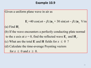
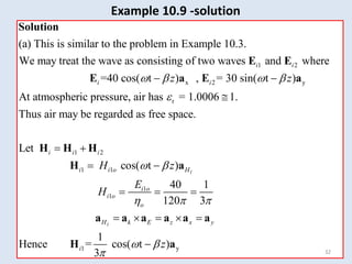
Example 10.9 -solution
2
2 2
1
1 k z z
1
2 2 2 2
z z
2 2
2
2 k z
2 2
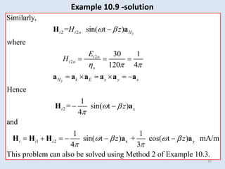
(d) For z 0,
| | 1
[ ]
2 2
1
= 40 30 40 30 =0
240
For z 0,
| |
0
2 2
because the whole incident power is reflected.
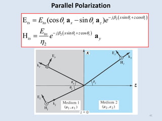
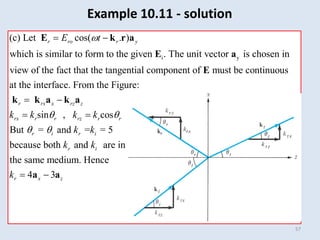
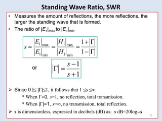
s
ave io ro
o
s to
ave
E
E E
E E
a a a
a a
a a](https://image.slidesharecdn.com/emii2013chapter10p2-240425125726-e970395a/85/tripple-e-136-EMII2013_Chapter_10_P2-pdf-35-320.jpg)
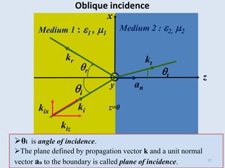
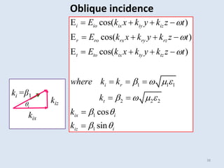
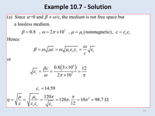
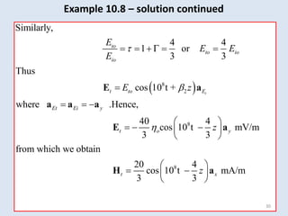
![36
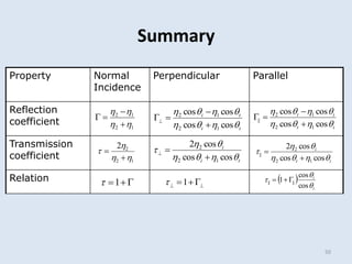
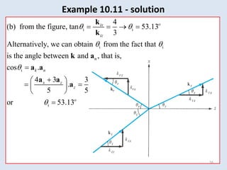
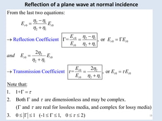
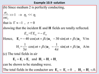
• Wave arrives at an angle.
• Assume lossless media.
• Uniform plane wave in general form
• For lossless unbounded media, k =
( )
2 2 2 2 2
( , ) cos( ) Re[ ]
ˆ ˆ ˆ position vector
ˆ ˆ ˆ wave number or propagation vector
j t
o o
x y z
x x y y z z
x y z
E t E t E e
xa ya za
k a k a k a
k k k k
k r
r k r
r
k
Oblique incidence](https://image.slidesharecdn.com/emii2013chapter10p2-240425125726-e970395a/85/tripple-e-136-EMII2013_Chapter_10_P2-pdf-36-320.jpg)