Downloaded 265 times


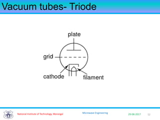
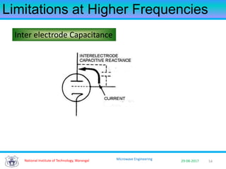
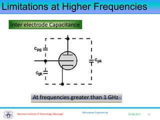
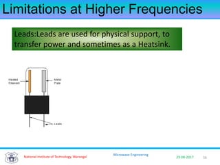
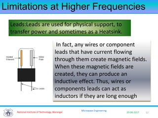
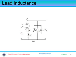
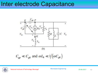
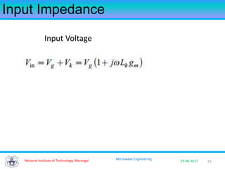
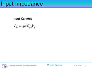
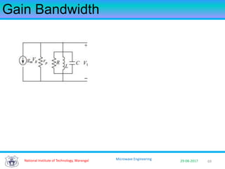
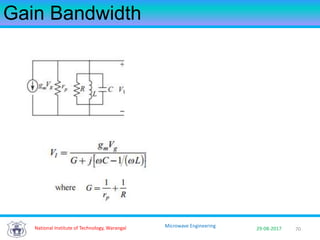
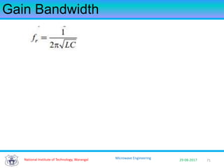
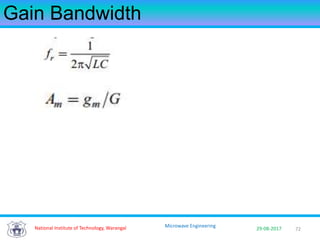
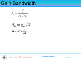
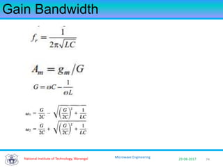
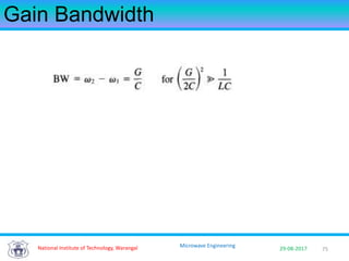
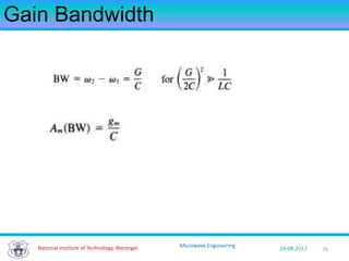
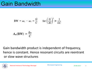
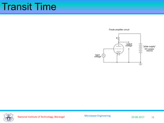
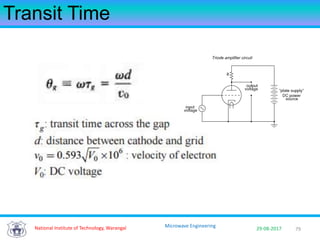
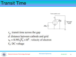


The document discusses limitations of vacuum tubes at microwave frequencies. Key limitations include increased parasitic inductance and capacitance from electrode leads, which reduce efficiency. Transit time effects also limit bandwidth as electrons oscillate between electrodes. Gain-bandwidth product remains constant, requiring alternative designs like reentrant cavities. Overall, vacuum tubes face challenges amplifying signals above 1 GHz due to these inherent timescale limitations. Solid state devices like transistors addressed these issues and enabled widespread microwave applications.


