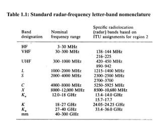
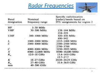
Radar
• Radio DetectionAnd Ranging
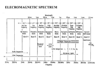
• RADIO Means it is using RADIO WAVES(we are working
signals in Radio frequency i.e., RF SIGNALS all in GHZ of
frequency i.e.,very high frequency)
• DETECTION main purpose of RADAR is to identify the
objects (wheather object is in visinity of radar system or
not)
• RANGING means DISTANCE ,along with identification it
finds distance between the object and radar system.
4
5.
RADAR DEFINATION
In simplewayRADAR uses Radio
frequiencies in order to identify the
presence of objects and also calculate the
distance between object and radar system
(if target is identified)
THIS IS MAIN MOTO OF RADAR
6.
INTRODUCTION TO RADAR
RADAR is all about using radio waves to detect
the presence of objects and to find their
position(distance)
Radar can see through conditions such as
darkness, haze, fog, rain, and snow which is not
possible for human vision.
Radar has the advantage of being able to
measure the distance (Range) to the object.
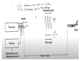
7.
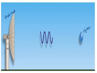
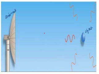
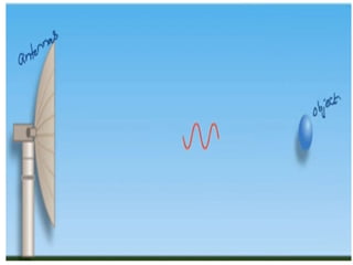
Radar simple operation
•It operates by radiating energy into space and
detecting the echo signal reflected from an object or
target.
In other words
• It sends the signal and collects back the reflected
signal ,depending upon the reflected signal strength
it identifies what is distance that the target is
located
(if echo signal is there then we can say target is there)
12.
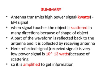
SUMMARY
• Antenna transmitshigh power signal(kwatts) -
EM signal
• when signal touches the object it scattered in
many directions because of shape of object
• A part of the waveform is reflected back to the
antenna and it is collected by receving antenna
• Here reflected signal (recevied signal) is very
low power signal is 10^-13 watts(because of
scattering
• so it is amplified to get information
13.
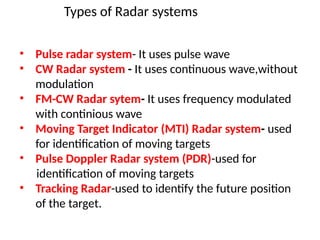
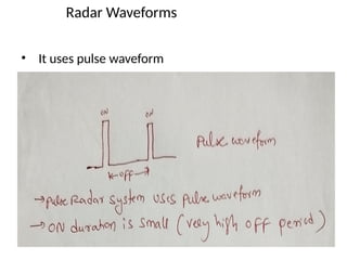
Types of Radarsystems
• Pulse radar system- It uses pulse wave
• CW Radar system - It uses continuous wave,without
modulation
• FM-CW Radar sytem- It uses frequency modulated
with continious wave
• Moving Target Indicator (MTI) Radar system- used
for identification of moving targets
• Pulse Doppler Radar system (PDR)-used for
identification of moving targets
• Tracking Radar-used to identify the future position
of the target.
15.
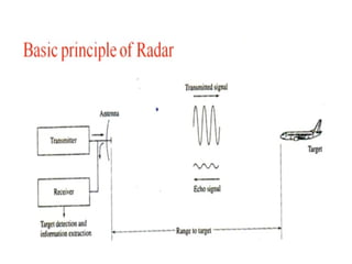
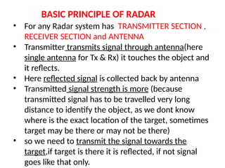
BASIC PRINCIPLE OFRADAR
• For any Radar system has TRANSMITTER SECTION ,
RECEIVER SECTION and ANTENNA
• Transmitter transmits signal through antenna(here
single antenna for Tx & Rx) it touches the object and
it reflects.
• Here reflected signal is collected back by antenna
• Transmitted signal strength is more (because
transmitted signal has to be travelled very long
distance to identify the object, as we dont know
where is the exact location of the target, sometimes
target may be there or may not be there)
• so we need to transmit the signal towards the
target,if target is there it is reflected, if not signal
goes like that only.
16.
• Reflected signalis collected back by antenna
• single antenna here in one time it is acting as
transmitting and in OFF time it is acting as
receiving antenna and it sends to receiver
• Recevied signal is processed to identify
“R”( distance between target and Radar system)
17.
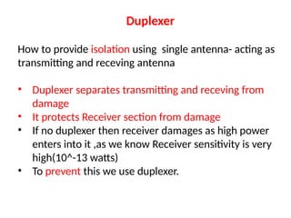
Duplexer
How to provideisolation using single antenna- acting as
transmitting and receving antenna
• Duplexer separates transmitting and receving from
damage
• It protects Receiver section from damage
• If no duplexer then receiver damages as high power
enters into it ,as we know Receiver sensitivity is very
high(10^-13 watts)
• To prevent this we use duplexer.
19.
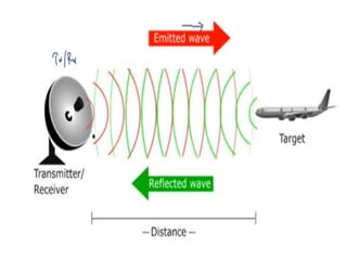
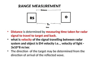
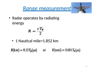
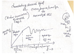
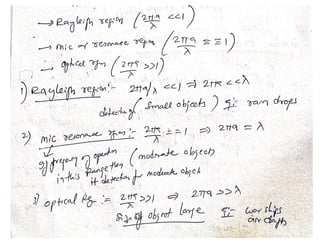
RANGE MEASUREMENT
• Distanceis determined by measuring time taken for radar
signal to travel to target and back.
• what is velocity of the signal travelling between radar
system and object is EM velocity i.e.., velocity of light -
3x10^8 m/sec
• The direction of the target may be determined from the
direction of arrival of the reflected wave.
20.
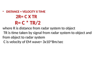
• DISTANCE =VELOCITY X TIME
2R= C X TR
R= C * TR/2
where R is distance from radar system to object
TR is time taken by signal from radar system to object and
from object to radar system
C is velocity of EM wave= 3x10^8m/sec
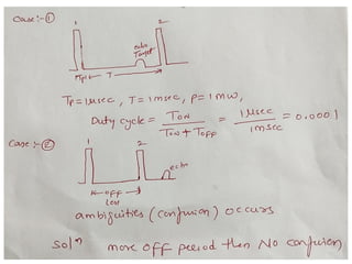
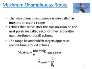
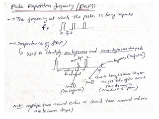
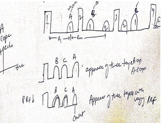
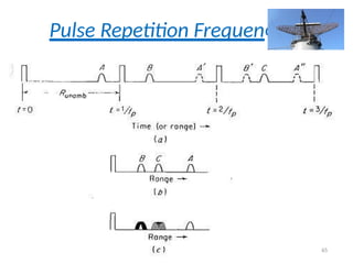
Maximum Unambiguous Range
•The maximum unambiguous is also called as
maximum usable range
• Echoes that arrive after the transmission of the
next pulse are called second-time- around(or
multiple-time-around) echoes.
• The range beyond which targets appear as
second-time-around echoes
Maximum
unambig
u ous range
24
25.
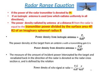
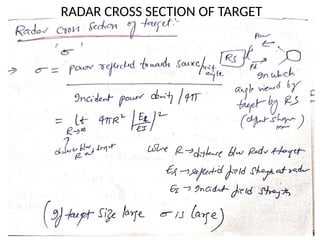
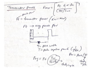
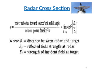
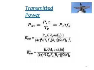
Radar Range Equation
•If the power of the radar transmitter is denoted by Pt
• If an isotropic antenna is used (one which radiates uniformly in all
directions),
• The power density radiated by antenna at a distance R from the radar is
equal to the transmitter power divided by the surface area 4Π
R2 of an imaginary sphereof radius R
•
The power density at the target from an antenn a with a transmitting gain G is
• The measure of the amount of incident power intercepted by the target and
reradiated back in the direction of the radar is denoted as the radar cross
section σ, and is defined by the relation
25
26.
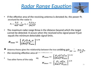
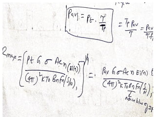
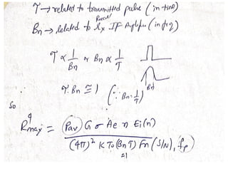
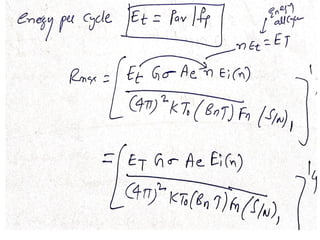
Radar Range Equation
•If the effective area of the receiving antenna is denoted Ae, the power Pr,
received by the radar is
• The maximum radar range Rmax is the distance beyond which the target
cannot be detected. It occurs when the received echo signal power P
,just
equals the minimum detectable signal Smin,
• Antenna theory gives the relationship between the tran smitting gain and
• the receiving effective area of an antenna as
• Two other forms of the rada
equartion
26
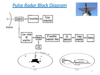
The operation ofa typical pulse radar is described with the help of a
simple block diagram shown in the figure below.
There are two sections of Radar system
i) Transmitter section ii) Receiver Section
Transmitter : The transmitter in Fig consists of pulse modulator which
generates pulse waveform for transmission.
Duplexer : The duplexer acts as a rapid switch to protect the receiver
from damage when the high-power transmitter is on.
Antenna:The transmitter power is radiated into space by antenna
Low noise RF Amplifier :The receiver is almost always a
Superheterodyne.
Mixer and Local oscillator:
The mixer and local oscillator convert the RF signal to the Intermediate
Frequency ( IF ).
IF Amplifier :
It amplifies the IF pulse. IF amplifier is designed as matched filter which
maximizes the output peak signal to mean noise ratio.
29.
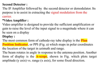
Second Detector :
TheIF Amplifier followed by the second detector or demodulator. Its
purpose is to assist in extracting the signal modulation from the
carrier.
Video Amplifier :
Video amplifier is designed to provide the sufficient amplification or
gain to raise the level of the input signal to a magnitude where it can
be seen on a display
Display :
The most common form of cathode-ray tube display is the Plan
Position Indicator, or PPI (Fig. a) which maps in polar coordinates
the location of the target in azimuth and range.
The beam rotates in angle in response to the antenna position. Another
form of display is the A-scope, shown in Fig. which plots target
amplitude (y axis) vs. range (x axis), for some fixed direction.
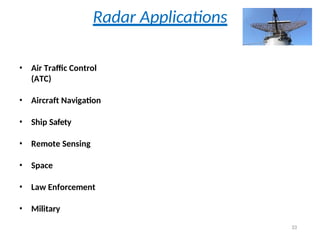
Radar Applications
• AirTraffic Control
(ATC)
• Aircraft Navigation
• Ship Safety
• Remote Sensing
• Space
• Law Enforcement
• Military
33
34.
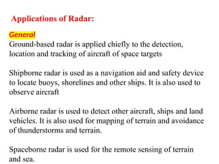
Applications of Radar:
General
Ground-basedradar is applied chiefly to the detection,
location and tracking of aircraft of space targets
Shipborne radar is used as a navigation aid and safety device
to locate buoys, shorelines and other ships. It is also used to
observe aircraft
Airborne radar is used to detect other aircraft, ships and land
vehicles. It is also used for mapping of terrain and avoidance
of thunderstorms and terrain.
Spaceborne radar is used for the remote sensing of terrain
and sea.
35.
Air Traffic Control:
Used to provide air traffic controllers with position and other
information on aircraft flying within their area of responsibility
(airways and in the vicinity of airports)
High resolution radar is used at large airports to monitor aircraft
and ground vehicles on the runways, taxiways and ramps.
GCA (ground controlled approach) or PAR (precision approach
radar) provides an operator with high accuracy aircraft position
information in both the vertical and horizontal. The operator uses
this information to guide the aircraft to a landing in bad weather.
MLS (microwave landing system) and ATC radar beacon systems
are based on radar technology
36.
Air Navigation :
Weatheravoidance radar is used on aircraft to detect and
display areas of heavy precipitation and turbulence
Terrain avoidance and terrain following radar (primarily military)
Radio altimeter (FM/CW or Pulse) – to measure height
Doppler navigator
Ground mapping radar of moderate resolution sometimes used
for navigation
37.
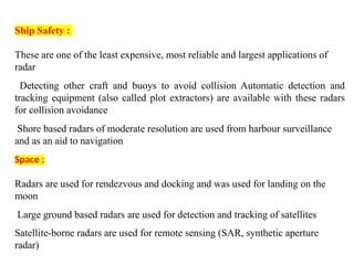
Ship Safety :
Theseare one of the least expensive, most reliable and largest applications of
radar
Detecting other craft and buoys to avoid collision Automatic detection and
tracking equipment (also called plot extractors) are available with these radars
for collision avoidance
Shore based radars of moderate resolution are used from harbour surveillance
and as an aid to navigation
Space :
Radars are used for rendezvous and docking and was used for landing on the
moon
Large ground based radars are used for detection and tracking of satellites
Satellite-borne radars are used for remote sensing (SAR, synthetic aperture
radar)
38.
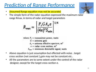
Prediction of RangePerformance
• (Assumed Range equation may not be accurate)
• The simple form of the radar equation expressed the maximum radar
range Rmax, in terms of radar and target parameters
• Above equation is just assumption but effected with noise , target
cross section (not constant ),gain may not be constant etc..
• All the parameters are to some extent under the control of the radar
designer, except for the target cross section σ.
38
39.
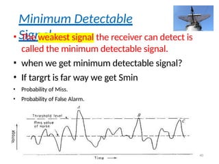
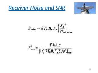
Minimum Detectable Signal
•The weakest signal the receiver can detect is called
the minimum detectable signal.
• If target is far away we get minimum detectable
signal.
• Detection is based on establishing a threshold level at
the output of the receiver.
• If the receiver output exceeds the threshold, a signal
is assumed to be present. This is called threshold
detection.
39
40.
Minimum Detectable
Signal
• Theweakest signal the receiver can detect is
called the minimum detectable signal.
• when we get minimum detectable signal?
• If targrt is far way we get Smin
• Probability of Miss.
• Probability of False Alarm.
40
41.
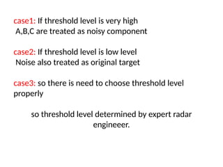
case1: If thresholdlevel is very high
A,B,C are treated as noisy component
case2: If threshold level is low level
Noise also treated as original target
case3: so there is need to choose threshold level
properly
so threshold level determined by expert radar
engineeer.
42.
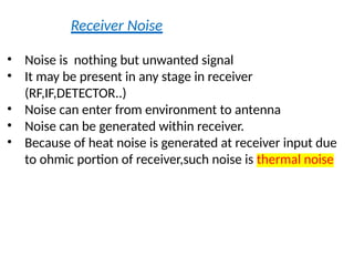
Receiver Noise
• Noiseis nothing but unwanted signal
• It may be present in any stage in receiver
(RF,IF,DETECTOR..)
• Noise can enter from environment to antenna
• Noise can be generated within receiver.
• Because of heat noise is generated at receiver input due
to ohmic portion of receiver,such noise is thermal noise
43.
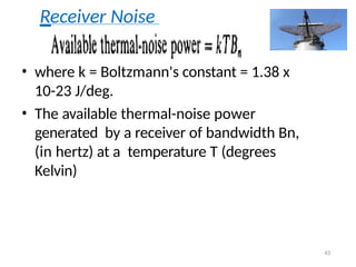
Receiver Noise
• wherek = Boltzmann's constant = 1.38 x
10-23 J/deg.
• The available thermal-noise power
generated by a receiver of bandwidth Bn,
(in hertz) at a temperature T (degrees
Kelvin)
43
44.
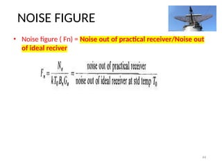
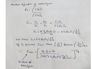
NOISE FIGURE
• Noisefigure ( Fn) = Noise out of practical receiver/Noise out
of ideal reciver
44
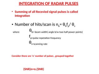
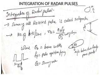
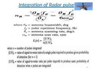
INTEGRATION OF RADARPULSES
• Summing of all Recevied signal pulses is called
Integration
• Number of hits/scan is nb= θbfp/ θs
where θb= beam width( angle b/w two half power points)
fp=pulse repetation frequency
θs=scanning rate
Consider there are ‘n’ number of pulses , grouped together
(SNR)n=n.(SNR)
48.
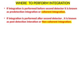
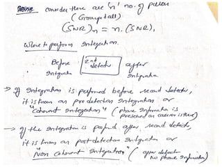
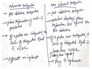
WHERE TO PERFORMINTEGRATION
• If integration is performed before second detector it is known
as predetection integration or coherent Integration.
• If integration is performed after second detector , it is known
as post detection interation or Non coherent Integration.