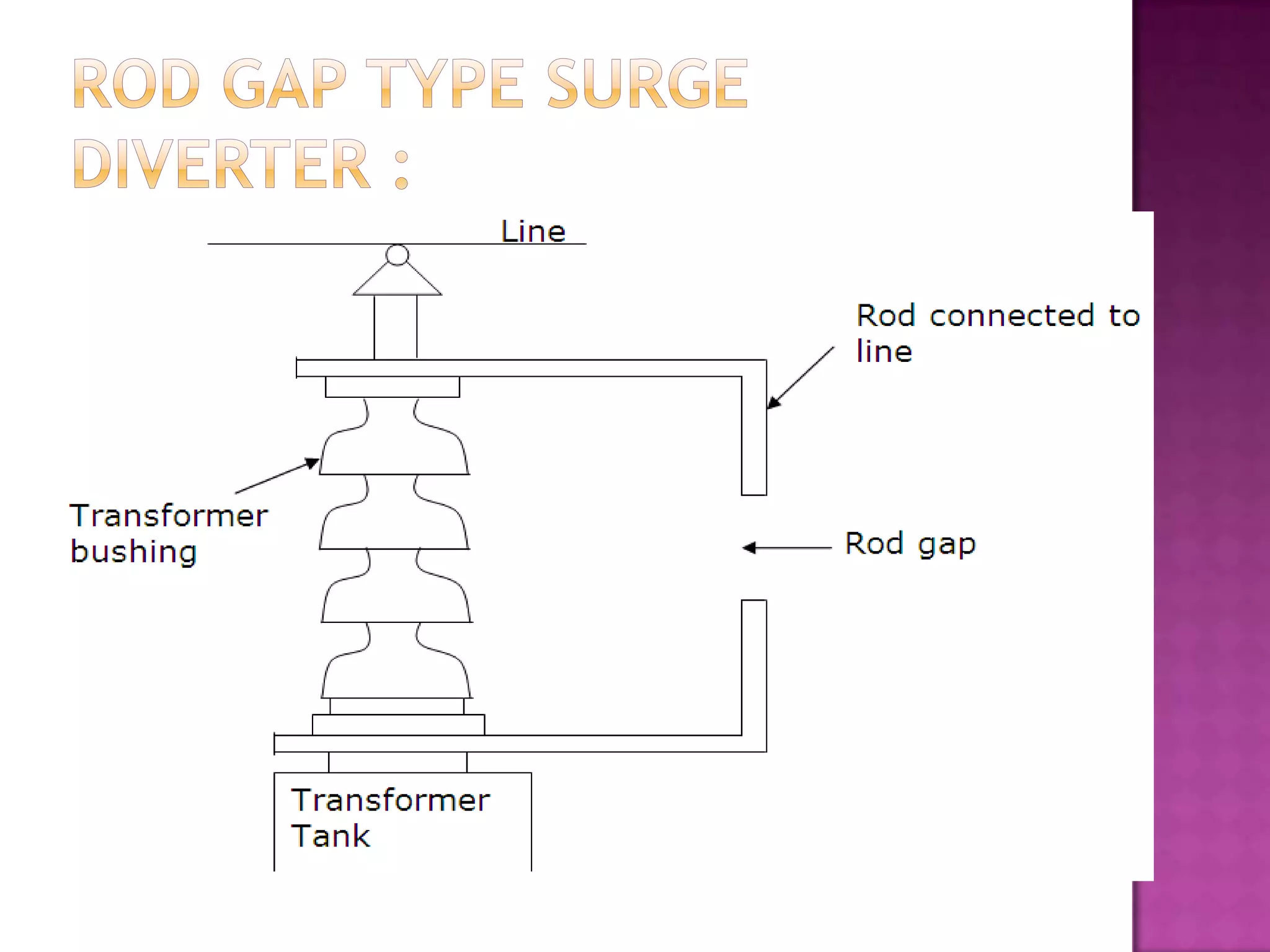
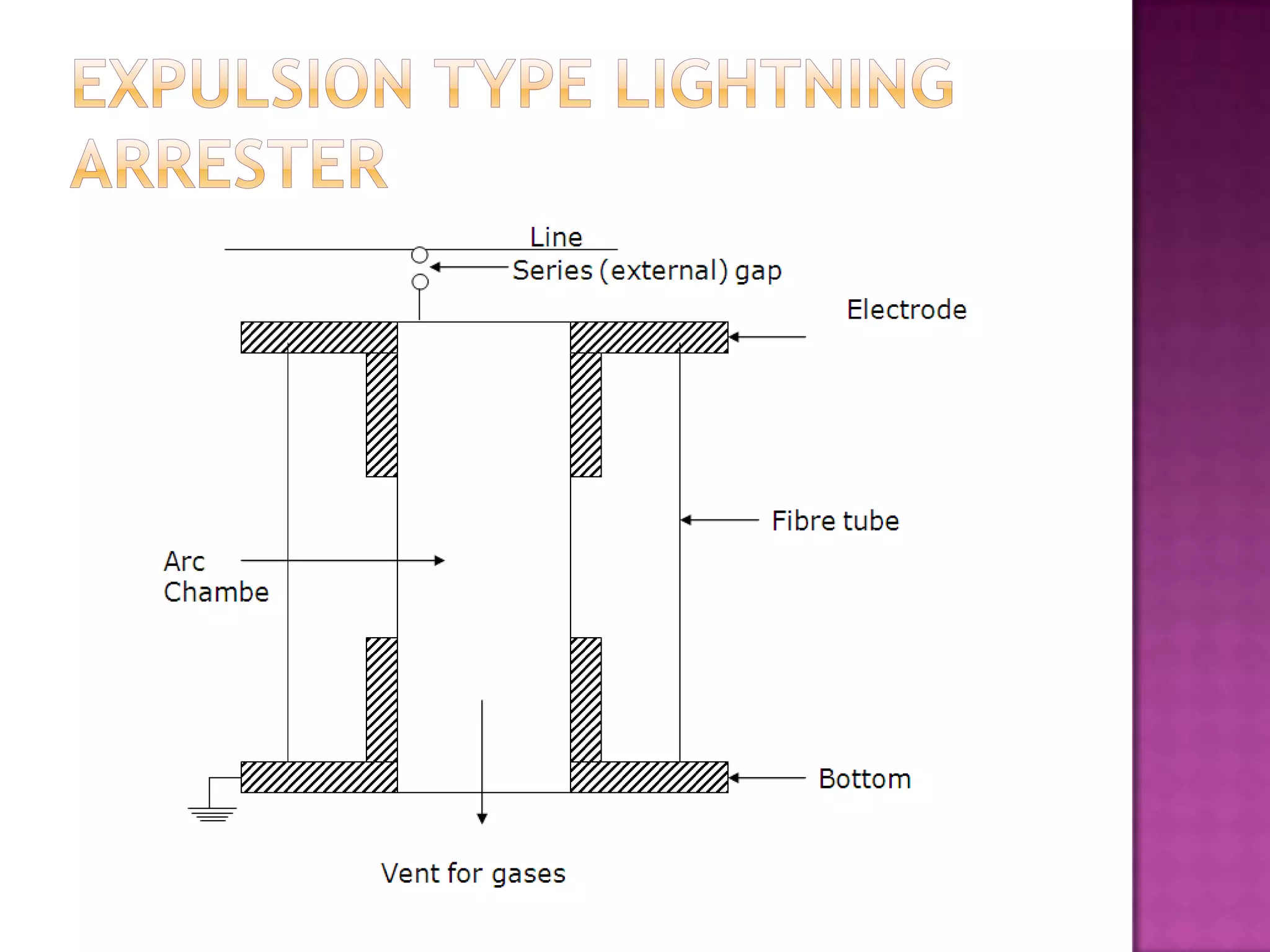
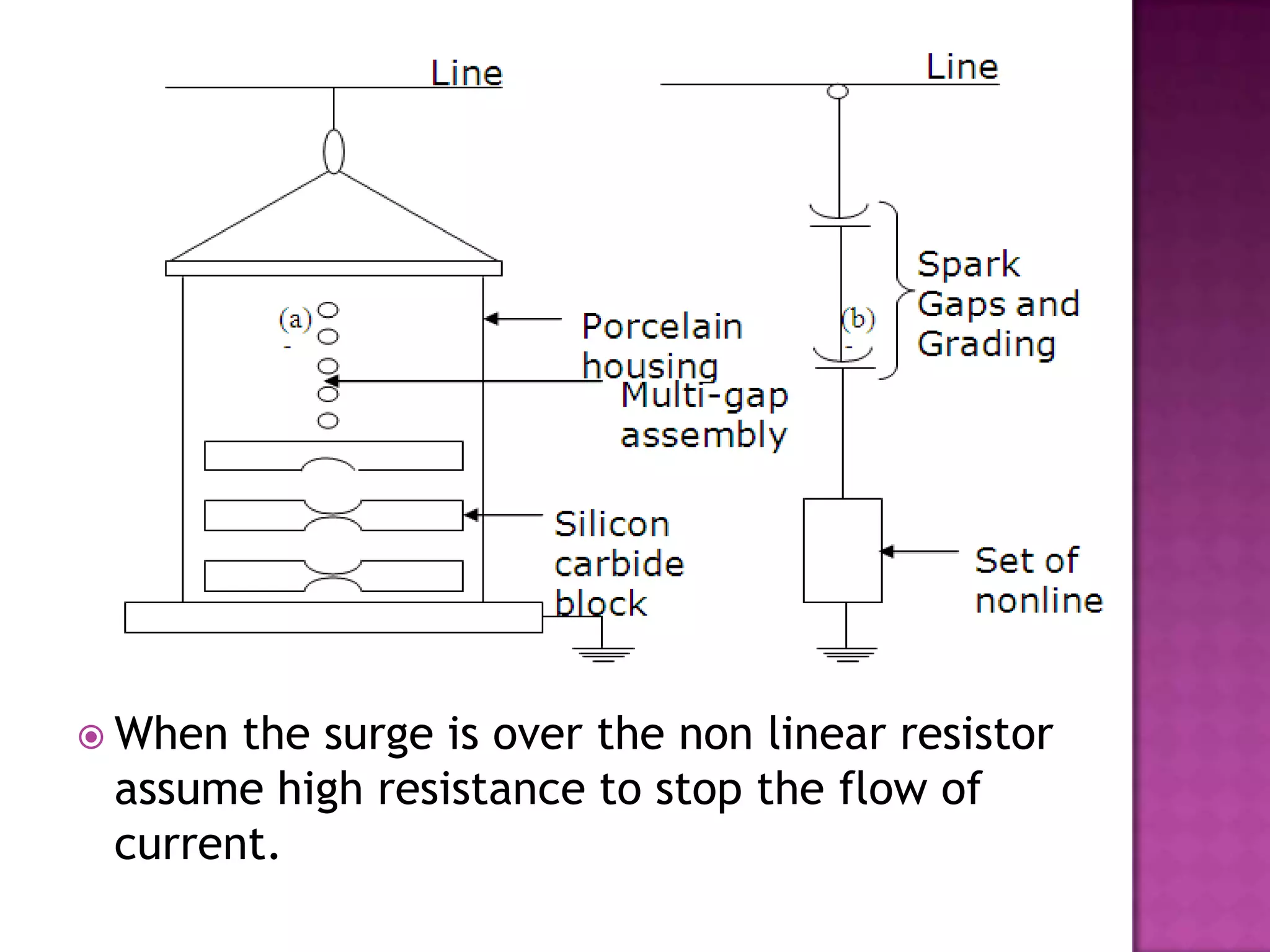
SlideShare a Scribd company logo
1 of 23
SURGE DIVERTER
 Surges,     or transients, are brief overvoltage
    spikes or disturbances on a power waveform
    that can damage, degrade, or destroy
    electronic equipment within any home,
    commercial building, or manufacturing
    facility.

 Transients  can reach amplitudes of tens of
    thousands of volts.

   Surges are measured in microseconds.
   A surge diverter is a piece of equipment that
    diverts excess voltages (caused by spikes in the
    electrical supply) to earth, thus protecting
    sensitive electrical and electronic equipment.

   The surge diverter is normally installed in the
    main switchboard.

    The surge diverter ‘shunts’ voltages over 260
    volts AC to ground, stopping most power spikes
    from causing any damage.
   It should not pass any current at normal and
    abnormal power frequency voltage.

   It should breakdown as quickly as possible after
    the abnormal high frequency voltage arrives.

   It should not only protect the equipment for
    which it is used but should discharge current
    without damaging itself.

   It should interrupt power frequency follow
    current after the surge is discharge to ground.
 Rod   gap

 Protector   tube or expulsion type surge
 diverter

 Valve   type surge diverter
 Itis a very simple type of diverter and
  consists of two 1.5 cm rods, which are bent
  at right angles with a gap in between.
 One rod is connected to the line circuit and
  the other rod is connected to earth.
 The distance between gap and insulator must
  not be less than one third of the gap length
  so that the arc may not reach the insulator
  and damage it.
 The rod gap should be so set that it breaks
  down to a voltage not less than 30% below
  the voltage withstand level of the equipment
  The string of insulators for an overhead line
  on the bushing of transformer has frequently a
  rod gap across it.
 Under normal operating conditions, the gap
  remains non-conducting.
 On the occurrence of a high voltage surge on
  the line, the gap sparks over and the surge
  current is conducted to earth.
 In this way excess charge on the line due to
  the surge is harmlessly conducted to earth
  After the surge is over, the arc in the gap is
  maintained by the normal supply voltage,
  leading to short-circuit on the system.
 The rods may melt or get damaged due to
  excessive heat produced by the arc.
 The climatic conditions (e.g. rain, humidity,
  temperature etc.) affect the performance of
  rod gap arrester.
 The polarity of the surge also affects the
  performance of this arrester.
 This type of arrester is also called ‘protector
  tube’ and is commonly used on system
  operating at voltages up to 33kV.
 It essentially consists of a rod gap in series
  with a second gap enclosed within the fiber
  tube.
 The gap in the fiber tube is formed by two
  electrodes.
 The upper electrode is connected to rod gap
  and the lower electrode to the earth.
 The series gap is set to arc over at a
  specified voltage lower than the withstand
  voltage of the equipment to be protected.
 The follow-on current is confined to the
  space inside the relatively small fibre tube.
 Part of the tube material vaporizes, and the
  high pressure gases so formed are expelled
  through the vent at the lower end of the
  tube, causing the power follow-in arc to be
  extinguished.
 The device, therefore, has the desired self-
  clearing property.
 They   are not very expensive.

 They   can be easily installed.

 They are improved form of rod gap arresters
 as they block the flow of power frequency
 follow currents.
 An expulsion type arrester can perform only
  limited number of operations as during each
  operation some of the fiber material is used
  up.
 This type of arrester cannot be mounted on
  enclosed equipment due to discharge of
  gases during operation.
 Due to the poor volt/amp characteristic of
  the arrester, it is not suitable for protection
  of expensive equipment
 Valve  type arresters incorporate non linear
  resistors and are extensively used on systems,
  operating at high voltages.
 It consists of two assemblies (i) series spark
  gaps and (ii) non-linear resistor discs
 The non-linear elements are connected in
  series with the spark gaps. Both the assemblies
  are accommodated in tight porcelain
  container.
 The spark gap is a multiple assembly
  consisting of a number of identical spark gaps
  in series.
 Each gap consists of two electrodes with fixed
  gap spacing.
 The  spacing of the series gaps is such that it
  will withstand the normal circuit voltage.
 An over voltage will cause the gap to break
  down causing the surge current to ground via
  the non-linear resistors.
 The non-linear resistor discs are made of
  inorganic compound such as thyrite or
  metrosil.
 These discs are connected in series.
 The non-linear resistors have the property of
  offering a high resistance to current flow when
  normal system voltage is applied, but a low
  resistance to the flow of high surge currents.
 When the surge is over the non linear resistor
 assume high resistance to stop the flow of
 current.
 Under   normal conditions, the normal system
  voltage is insufficient to cause the breakdown
  of air gap assembly.
 On the occurrence of an over voltage, the
  breakdown of the series spark gap takes place
  and the surge current is conducted to earth via
  the nonlinear resistances.
 Since the magnitude of surge current is very
  large, the nonlinear elements will offer a very
  low resistance to the passage of surge.
 The surge will rapidly go to earth instead of
  being sent back over the line.
 They provide very effective protection against
 surges.
 They operate very rapidly taking less than a
 second
 The impulse ratio is practically unity.
 They may fail to check the surge of very steep
 wave front reaching the terminal apparatus.
 This calls for additional steps to check steep
 fronted waves.
 Their performance is adversely affected by the
 entry of moisture into the enclosure. This
 necessitates effective sealing of the enclosure
 at all times.
 As  a voltage surge
  travelling on the
  line reaches the
  surge diverter, it
  breaks down at a
  specified voltage
  Vbd.
 The voltage across
  the diverter
  instantly dips and
  as the surge
  current show
  discharges through
  it, a constant
  voltage of value
  Vr(residual voltag)
Protect Equipment from Power Surges with a Surge Diverter

More Related Content

What's hot

Power Transformer Protection
Power Transformer ProtectionPower Transformer Protection
Power Transformer ProtectionAng Sovann
 
Ppt on protection of power transformers
Ppt on protection of power transformersPpt on protection of power transformers
Ppt on protection of power transformerssiddharam kantoli
 
Unit 03 Protective relays
Unit  03 Protective relaysUnit  03 Protective relays
Unit 03 Protective relaysPremanandDesai
 
Power electronics Phase Controlled Rectifiers - SCR
Power electronics   Phase Controlled Rectifiers - SCRPower electronics   Phase Controlled Rectifiers - SCR
Power electronics Phase Controlled Rectifiers - SCRBurdwan University
 
Hv module 3 Impulse voltage generation
Hv module 3 Impulse voltage generationHv module 3 Impulse voltage generation
Hv module 3 Impulse voltage generationAsha Anu Kurian
 
UNSYMMETRICAL FAULTS IN POWER SYSTEM
UNSYMMETRICAL FAULTS IN POWER SYSTEMUNSYMMETRICAL FAULTS IN POWER SYSTEM
UNSYMMETRICAL FAULTS IN POWER SYSTEMerramansaini1947
 
Generation of High D.C. Voltage (HVDC generation)
Generation of High D.C. Voltage (HVDC generation)Generation of High D.C. Voltage (HVDC generation)
Generation of High D.C. Voltage (HVDC generation)RP6997
 
Transient in Power system
Transient in Power systemTransient in Power system
Transient in Power systemPreet_patel
 
Alternator protection
Alternator protectionAlternator protection
Alternator protectionjawaharramaya
 
Capacitive voltage transformer (1)
Capacitive voltage transformer (1)Capacitive voltage transformer (1)
Capacitive voltage transformer (1)kaushal boghani
 
Unit 2 Reactive Power Management
Unit 2 Reactive Power ManagementUnit 2 Reactive Power Management
Unit 2 Reactive Power ManagementSANTOSH GADEKAR
 
Basic types of facts controllers
Basic types of facts controllersBasic types of facts controllers
Basic types of facts controllersAyyarao T S L V
 
Measurement of high_voltage_and_high_currentunit_iv_full_version
Measurement of high_voltage_and_high_currentunit_iv_full_versionMeasurement of high_voltage_and_high_currentunit_iv_full_version
Measurement of high_voltage_and_high_currentunit_iv_full_versionAman Ansari
 
Tutorial on Distance and Over Current Protection
Tutorial on Distance and Over  Current ProtectionTutorial on Distance and Over  Current Protection
Tutorial on Distance and Over Current ProtectionSARAVANAN A
 

What's hot (20)

Power Transformer Protection
Power Transformer ProtectionPower Transformer Protection
Power Transformer Protection
 
Ppt on protection of power transformers
Ppt on protection of power transformersPpt on protection of power transformers
Ppt on protection of power transformers
 
Unit 03 Protective relays
Unit  03 Protective relaysUnit  03 Protective relays
Unit 03 Protective relays
 
Power electronics Phase Controlled Rectifiers - SCR
Power electronics   Phase Controlled Rectifiers - SCRPower electronics   Phase Controlled Rectifiers - SCR
Power electronics Phase Controlled Rectifiers - SCR
 
Hv module 3 Impulse voltage generation
Hv module 3 Impulse voltage generationHv module 3 Impulse voltage generation
Hv module 3 Impulse voltage generation
 
Streamer theory
Streamer theoryStreamer theory
Streamer theory
 
UNSYMMETRICAL FAULTS IN POWER SYSTEM
UNSYMMETRICAL FAULTS IN POWER SYSTEMUNSYMMETRICAL FAULTS IN POWER SYSTEM
UNSYMMETRICAL FAULTS IN POWER SYSTEM
 
Generation of High D.C. Voltage (HVDC generation)
Generation of High D.C. Voltage (HVDC generation)Generation of High D.C. Voltage (HVDC generation)
Generation of High D.C. Voltage (HVDC generation)
 
Transient in Power system
Transient in Power systemTransient in Power system
Transient in Power system
 
Alternator protection
Alternator protectionAlternator protection
Alternator protection
 
Capacitive voltage transformer (1)
Capacitive voltage transformer (1)Capacitive voltage transformer (1)
Capacitive voltage transformer (1)
 
PPT ON POWER SYSTEM STABILITY
PPT ON POWER SYSTEM STABILITYPPT ON POWER SYSTEM STABILITY
PPT ON POWER SYSTEM STABILITY
 
Power quality ppt
Power quality pptPower quality ppt
Power quality ppt
 
Unit 2 Reactive Power Management
Unit 2 Reactive Power ManagementUnit 2 Reactive Power Management
Unit 2 Reactive Power Management
 
Motor Protection
Motor ProtectionMotor Protection
Motor Protection
 
Basic types of facts controllers
Basic types of facts controllersBasic types of facts controllers
Basic types of facts controllers
 
Measurement of high_voltage_and_high_currentunit_iv_full_version
Measurement of high_voltage_and_high_currentunit_iv_full_versionMeasurement of high_voltage_and_high_currentunit_iv_full_version
Measurement of high_voltage_and_high_currentunit_iv_full_version
 
Statcom
StatcomStatcom
Statcom
 
Protection of alternator
Protection of alternatorProtection of alternator
Protection of alternator
 
Tutorial on Distance and Over Current Protection
Tutorial on Distance and Over  Current ProtectionTutorial on Distance and Over  Current Protection
Tutorial on Distance and Over Current Protection
 

Viewers also liked

surge diverters
surge diverterssurge diverters
surge divertersnehakardam
 
HueMore
HueMoreHueMore
HueMoreekux44
 
Unit 4[1]
Unit 4[1]Unit 4[1]
Unit 4[1]mog20
 
Practical Earthing, Bonding, Lightning and Surge Protection
Practical Earthing, Bonding, Lightning and Surge ProtectionPractical Earthing, Bonding, Lightning and Surge Protection
Practical Earthing, Bonding, Lightning and Surge ProtectionLiving Online
 
Surge arrester and surge suppressor on transformer
Surge arrester and surge suppressor on transformerSurge arrester and surge suppressor on transformer
Surge arrester and surge suppressor on transformerVIKAS KUMAR MANJHI
 
Neutral Grounding
Neutral GroundingNeutral Grounding
Neutral GroundingNoman Nomi
 
Dielectric Material and properties
Dielectric Material and propertiesDielectric Material and properties
Dielectric Material and propertiesMayank Pandey
 
Electric Current
Electric CurrentElectric Current
Electric Currentjeric lora
 
**Lightning Arrester Presentation**
**Lightning Arrester Presentation****Lightning Arrester Presentation**
**Lightning Arrester Presentation**SKPAMB
 
open channel flow
open channel flowopen channel flow
open channel flowGeoRuizO
 

Viewers also liked (20)

surge diverters
surge diverterssurge diverters
surge diverters
 
Lighting arrester
Lighting arresterLighting arrester
Lighting arrester
 
1 resistance
1 resistance1 resistance
1 resistance
 
Faraday cage
Faraday cageFaraday cage
Faraday cage
 
HueMore
HueMoreHueMore
HueMore
 
Surge supressor
Surge supressorSurge supressor
Surge supressor
 
study of lightning arrester
study of lightning arresterstudy of lightning arrester
study of lightning arrester
 
Unit 4[1]
Unit 4[1]Unit 4[1]
Unit 4[1]
 
Surge arrester
Surge arresterSurge arrester
Surge arrester
 
Power Management in BMS
Power Management in BMSPower Management in BMS
Power Management in BMS
 
Practical Earthing, Bonding, Lightning and Surge Protection
Practical Earthing, Bonding, Lightning and Surge ProtectionPractical Earthing, Bonding, Lightning and Surge Protection
Practical Earthing, Bonding, Lightning and Surge Protection
 
Surge arrester and surge suppressor on transformer
Surge arrester and surge suppressor on transformerSurge arrester and surge suppressor on transformer
Surge arrester and surge suppressor on transformer
 
Neutral Grounding
Neutral GroundingNeutral Grounding
Neutral Grounding
 
Lightning Arrestar
Lightning ArrestarLightning Arrestar
Lightning Arrestar
 
Dielectric Material and properties
Dielectric Material and propertiesDielectric Material and properties
Dielectric Material and properties
 
Lightning arresters
Lightning arrestersLightning arresters
Lightning arresters
 
Electric Current
Electric CurrentElectric Current
Electric Current
 
**Lightning Arrester Presentation**
**Lightning Arrester Presentation****Lightning Arrester Presentation**
**Lightning Arrester Presentation**
 
open channel flow
open channel flowopen channel flow
open channel flow
 
Surge in compressor
Surge in compressorSurge in compressor
Surge in compressor
 

Similar to Protect Equipment from Power Surges with a Surge Diverter

Similar to Protect Equipment from Power Surges with a Surge Diverter (20)

Lightning arrester
Lightning arresterLightning arrester
Lightning arrester
 
Lightning Arrester Working Principle & Types
Lightning Arrester Working Principle & TypesLightning Arrester Working Principle & Types
Lightning Arrester Working Principle & Types
 
Protection Devices and the Lightning
Protection Devices and the LightningProtection Devices and the Lightning
Protection Devices and the Lightning
 
Over voltage(Switch Gear and Protection)
Over voltage(Switch Gear and Protection)Over voltage(Switch Gear and Protection)
Over voltage(Switch Gear and Protection)
 
Shruthi
ShruthiShruthi
Shruthi
 
Lightning arresters
Lightning arrestersLightning arresters
Lightning arresters
 
Experiments manual
Experiments manual Experiments manual
Experiments manual
 
Lightening Arrester.pptx
Lightening Arrester.pptxLightening Arrester.pptx
Lightening Arrester.pptx
 
Circuit breaker
Circuit breakerCircuit breaker
Circuit breaker
 
Surge arrester ppt
Surge arrester pptSurge arrester ppt
Surge arrester ppt
 
Circuit breaker
Circuit breakerCircuit breaker
Circuit breaker
 
GIS and Over voltages.ppt
GIS and Over voltages.pptGIS and Over voltages.ppt
GIS and Over voltages.ppt
 
E04523236
E04523236E04523236
E04523236
 
Switchgear and Protection of HV Systems
Switchgear and Protection of HV SystemsSwitchgear and Protection of HV Systems
Switchgear and Protection of HV Systems
 
GIS substation Information (Detailed Report)
GIS substation Information (Detailed Report)GIS substation Information (Detailed Report)
GIS substation Information (Detailed Report)
 
Mcb, rccb, elcb
Mcb, rccb, elcbMcb, rccb, elcb
Mcb, rccb, elcb
 
Amanppt 140826070457-phpapp02
Amanppt 140826070457-phpapp02Amanppt 140826070457-phpapp02
Amanppt 140826070457-phpapp02
 
132KV SUBSTATION UPPTCL
132KV SUBSTATION UPPTCL132KV SUBSTATION UPPTCL
132KV SUBSTATION UPPTCL
 
s.pdf
s.pdfs.pdf
s.pdf
 
Lecture-PS-faults-description-recorded-30032020-110109pm.pptx
Lecture-PS-faults-description-recorded-30032020-110109pm.pptxLecture-PS-faults-description-recorded-30032020-110109pm.pptx
Lecture-PS-faults-description-recorded-30032020-110109pm.pptx
 

Protect Equipment from Power Surges with a Surge Diverter

  • 2.  Surges, or transients, are brief overvoltage spikes or disturbances on a power waveform that can damage, degrade, or destroy electronic equipment within any home, commercial building, or manufacturing facility.  Transients can reach amplitudes of tens of thousands of volts.  Surges are measured in microseconds.
  • 3. A surge diverter is a piece of equipment that diverts excess voltages (caused by spikes in the electrical supply) to earth, thus protecting sensitive electrical and electronic equipment.  The surge diverter is normally installed in the main switchboard.  The surge diverter ‘shunts’ voltages over 260 volts AC to ground, stopping most power spikes from causing any damage.
  • 4.
  • 5. It should not pass any current at normal and abnormal power frequency voltage.  It should breakdown as quickly as possible after the abnormal high frequency voltage arrives.  It should not only protect the equipment for which it is used but should discharge current without damaging itself.  It should interrupt power frequency follow current after the surge is discharge to ground.
  • 6.  Rod gap  Protector tube or expulsion type surge diverter  Valve type surge diverter
  • 7.  Itis a very simple type of diverter and consists of two 1.5 cm rods, which are bent at right angles with a gap in between.  One rod is connected to the line circuit and the other rod is connected to earth.  The distance between gap and insulator must not be less than one third of the gap length so that the arc may not reach the insulator and damage it.  The rod gap should be so set that it breaks down to a voltage not less than 30% below the voltage withstand level of the equipment
  • 8.  The string of insulators for an overhead line on the bushing of transformer has frequently a rod gap across it.  Under normal operating conditions, the gap remains non-conducting.  On the occurrence of a high voltage surge on the line, the gap sparks over and the surge current is conducted to earth.  In this way excess charge on the line due to the surge is harmlessly conducted to earth
  • 9.
  • 10.  After the surge is over, the arc in the gap is maintained by the normal supply voltage, leading to short-circuit on the system.  The rods may melt or get damaged due to excessive heat produced by the arc.  The climatic conditions (e.g. rain, humidity, temperature etc.) affect the performance of rod gap arrester.  The polarity of the surge also affects the performance of this arrester.
  • 11.  This type of arrester is also called ‘protector tube’ and is commonly used on system operating at voltages up to 33kV.  It essentially consists of a rod gap in series with a second gap enclosed within the fiber tube.  The gap in the fiber tube is formed by two electrodes.  The upper electrode is connected to rod gap and the lower electrode to the earth.
  • 12.
  • 13.  The series gap is set to arc over at a specified voltage lower than the withstand voltage of the equipment to be protected.  The follow-on current is confined to the space inside the relatively small fibre tube.  Part of the tube material vaporizes, and the high pressure gases so formed are expelled through the vent at the lower end of the tube, causing the power follow-in arc to be extinguished.  The device, therefore, has the desired self- clearing property.
  • 14.  They are not very expensive.  They can be easily installed.  They are improved form of rod gap arresters as they block the flow of power frequency follow currents.
  • 15.  An expulsion type arrester can perform only limited number of operations as during each operation some of the fiber material is used up.  This type of arrester cannot be mounted on enclosed equipment due to discharge of gases during operation.  Due to the poor volt/amp characteristic of the arrester, it is not suitable for protection of expensive equipment
  • 16.  Valve type arresters incorporate non linear resistors and are extensively used on systems, operating at high voltages.  It consists of two assemblies (i) series spark gaps and (ii) non-linear resistor discs  The non-linear elements are connected in series with the spark gaps. Both the assemblies are accommodated in tight porcelain container.  The spark gap is a multiple assembly consisting of a number of identical spark gaps in series.  Each gap consists of two electrodes with fixed gap spacing.
  • 17.  The spacing of the series gaps is such that it will withstand the normal circuit voltage.  An over voltage will cause the gap to break down causing the surge current to ground via the non-linear resistors.  The non-linear resistor discs are made of inorganic compound such as thyrite or metrosil.  These discs are connected in series.  The non-linear resistors have the property of offering a high resistance to current flow when normal system voltage is applied, but a low resistance to the flow of high surge currents.
  • 18.  When the surge is over the non linear resistor assume high resistance to stop the flow of current.
  • 19.  Under normal conditions, the normal system voltage is insufficient to cause the breakdown of air gap assembly.  On the occurrence of an over voltage, the breakdown of the series spark gap takes place and the surge current is conducted to earth via the nonlinear resistances.  Since the magnitude of surge current is very large, the nonlinear elements will offer a very low resistance to the passage of surge.  The surge will rapidly go to earth instead of being sent back over the line.
  • 20.  They provide very effective protection against surges.  They operate very rapidly taking less than a second  The impulse ratio is practically unity.
  • 21.  They may fail to check the surge of very steep wave front reaching the terminal apparatus. This calls for additional steps to check steep fronted waves.  Their performance is adversely affected by the entry of moisture into the enclosure. This necessitates effective sealing of the enclosure at all times.
  • 22.  As a voltage surge travelling on the line reaches the surge diverter, it breaks down at a specified voltage Vbd.  The voltage across the diverter instantly dips and as the surge current show discharges through it, a constant voltage of value Vr(residual voltag)