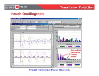
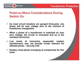
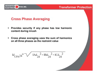
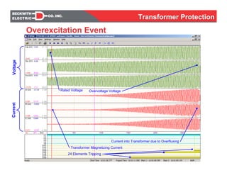
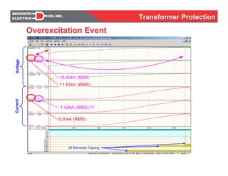
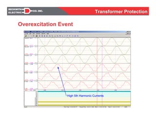
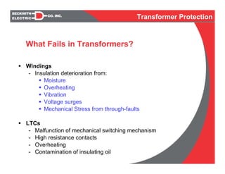
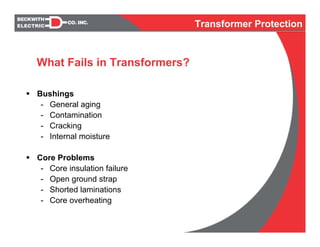
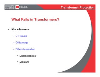
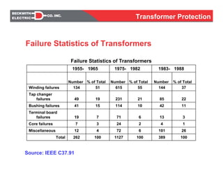
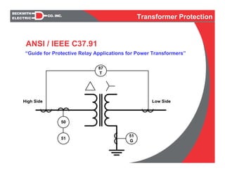
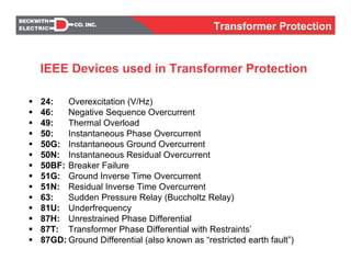
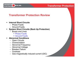
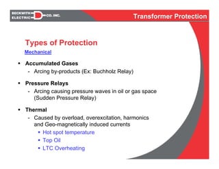
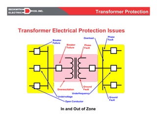
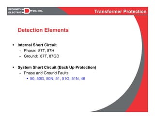
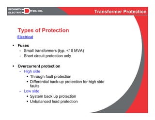
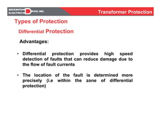
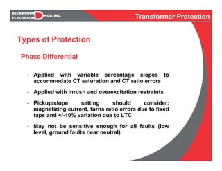
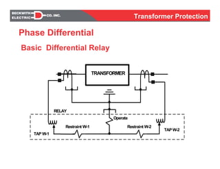
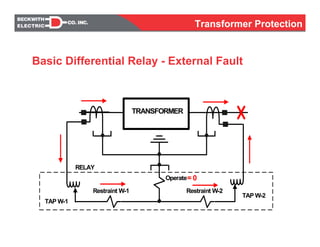
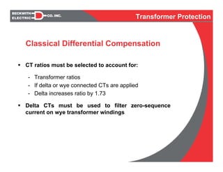
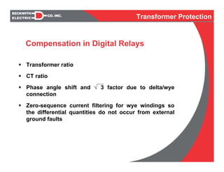
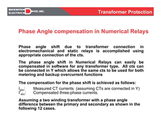
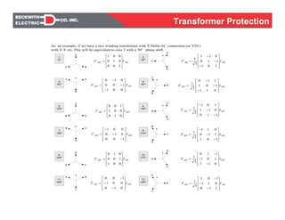
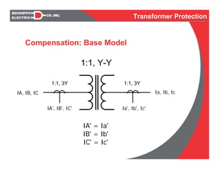
The document discusses transformer protection. It describes various failures that can occur in transformers such as winding failures, bushing failures, and tap changer failures. It provides statistics on historical transformer failures. It also discusses different types of protection for transformers including electrical protection methods like differential protection, overcurrent protection, overexcitation protection and thermal protection. Internal short circuits, system short circuits, and abnormal conditions are some of the issues addressed by transformer protection schemes.
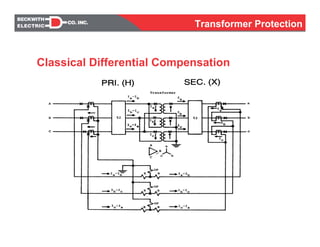
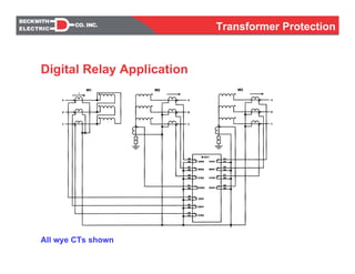
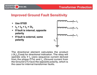
The following topics are covered: components of power distribution systems, fuses, padmounted transformers, pole mounted transformers, vault installed transformers, transformer stations protection, transformer connections, thermometers, pressure relief devices, restricted ground faults, differential protection current transformers connections, overexcitation, inrush current, percentage differential relays, gas relays, characteristics of CTs.
How is power transformer protected??? This provides a basic understanding of power transformer. Furthermore, the protective relay application on power transformer is included.
To sense/detect the fault occurrence and other abnormal conditions at the protected equipment/area/section.
To operate the correct circuit breakers so as to disconnect only the faulty equipment/area/section as quickly as possible, thus minimizing the damage caused by the faults.
To operate the correct circuit breakers to isolate the faulty equipment/area/section from the healthy system in the case of abnormalities like overloads, unbalance, undervoltage, etc.
To clear the fault before the system becomes unstable.
To identify distinctly where the fault has occurred.
Practical handbook-for-relay-protection-engineersSARAVANAN A
The ‘Hand Book’ covers the Code of Practice in Protection Circuitry including standard lead and device numbers, mode of connections at terminal strips, colour codes in multicore cables, Dos and Donts in execution. Also, principles of various protective relays and schemes including special protection schemes like differential,
restricted, directional and distance relays are explained with sketches. The norms of protection of generators, transformers, lines & Capacitor Banks are also given.
Test done on Power transformers.
Insulation Resistance test, Winding Resistance test, Ratio Measurements, Magnetic balance test, Tan delta test, DIssolved gas analysis for transformer, Sweep frequency response analysis.
We are providing info about power transformer parts and their functions. Power transformer is very useful in transmission network of higher voltage for step-up and step down.
Tan delta is the insulation power factor & is equal to the ratio of power dissipated in the insulation in watts to the product of effective voltage & current in volt ampere when tested under sinusoidal voltage.
Why do Transformers Fail?
�The electrical windings and the magnetic core in a transformer are subject to a number of different forces during operation, for example:
�Expansion and contraction due to thermal cycling
�Vibration
�Local heating due to magnetic flux
�Impact forces due to through-fault current
�Excessive heating due to overloading or inadequate cooling
Hybrid optimization of pumped hydro system and solar- Engr. Abdul-Azeez.pdffxintegritypublishin
Advancements in technology unveil a myriad of electrical and electronic breakthroughs geared towards efficiently harnessing limited resources to meet human energy demands. The optimization of hybrid solar PV panels and pumped hydro energy supply systems plays a pivotal role in utilizing natural resources effectively. This initiative not only benefits humanity but also fosters environmental sustainability. The study investigated the design optimization of these hybrid systems, focusing on understanding solar radiation patterns, identifying geographical influences on solar radiation, formulating a mathematical model for system optimization, and determining the optimal configuration of PV panels and pumped hydro storage. Through a comparative analysis approach and eight weeks of data collection, the study addressed key research questions related to solar radiation patterns and optimal system design. The findings highlighted regions with heightened solar radiation levels, showcasing substantial potential for power generation and emphasizing the system's efficiency. Optimizing system design significantly boosted power generation, promoted renewable energy utilization, and enhanced energy storage capacity. The study underscored the benefits of optimizing hybrid solar PV panels and pumped hydro energy supply systems for sustainable energy usage. Optimizing the design of solar PV panels and pumped hydro energy supply systems as examined across diverse climatic conditions in a developing country, not only enhances power generation but also improves the integration of renewable energy sources and boosts energy storage capacities, particularly beneficial for less economically prosperous regions. Additionally, the study provides valuable insights for advancing energy research in economically viable areas. Recommendations included conducting site-specific assessments, utilizing advanced modeling tools, implementing regular maintenance protocols, and enhancing communication among system components.
Immunizing Image Classifiers Against Localized Adversary Attacksgerogepatton
This paper addresses the vulnerability of deep learning models, particularly convolutional neural networks
(CNN)s, to adversarial attacks and presents a proactive training technique designed to counter them. We
introduce a novel volumization algorithm, which transforms 2D images into 3D volumetric representations.
When combined with 3D convolution and deep curriculum learning optimization (CLO), itsignificantly improves
the immunity of models against localized universal attacks by up to 40%. We evaluate our proposed approach
using contemporary CNN architectures and the modified Canadian Institute for Advanced Research (CIFAR-10
and CIFAR-100) and ImageNet Large Scale Visual Recognition Challenge (ILSVRC12) datasets, showcasing
accuracy improvements over previous techniques. The results indicate that the combination of the volumetric
input and curriculum learning holds significant promise for mitigating adversarial attacks without necessitating
adversary training.
CFD Simulation of By-pass Flow in a HRSG module by R&R Consult.pptxR&R Consult
CFD analysis is incredibly effective at solving mysteries and improving the performance of complex systems!
Here's a great example: At a large natural gas-fired power plant, where they use waste heat to generate steam and energy, they were puzzled that their boiler wasn't producing as much steam as expected.
R&R and Tetra Engineering Group Inc. were asked to solve the issue with reduced steam production.
An inspection had shown that a significant amount of hot flue gas was bypassing the boiler tubes, where the heat was supposed to be transferred.
R&R Consult conducted a CFD analysis, which revealed that 6.3% of the flue gas was bypassing the boiler tubes without transferring heat. The analysis also showed that the flue gas was instead being directed along the sides of the boiler and between the modules that were supposed to capture the heat. This was the cause of the reduced performance.
Based on our results, Tetra Engineering installed covering plates to reduce the bypass flow. This improved the boiler's performance and increased electricity production.
It is always satisfying when we can help solve complex challenges like this. Do your systems also need a check-up or optimization? Give us a call!
Work done in cooperation with James Malloy and David Moelling from Tetra Engineering.
More examples of our work https://www.r-r-consult.dk/en/cases-en/
Cosmetic shop management system project report.pdfKamal Acharya
Buying new cosmetic products is difficult. It can even be scary for those who have sensitive skin and are prone to skin trouble. The information needed to alleviate this problem is on the back of each product, but it's thought to interpret those ingredient lists unless you have a background in chemistry.
Instead of buying and hoping for the best, we can use data science to help us predict which products may be good fits for us. It includes various function programs to do the above mentioned tasks.
Data file handling has been effectively used in the program.
The automated cosmetic shop management system should deal with the automation of general workflow and administration process of the shop. The main processes of the system focus on customer's request where the system is able to search the most appropriate products and deliver it to the customers. It should help the employees to quickly identify the list of cosmetic product that have reached the minimum quantity and also keep a track of expired date for each cosmetic product. It should help the employees to find the rack number in which the product is placed.It is also Faster and more efficient way.
Industrial Training at Shahjalal Fertilizer Company Limited (SFCL)MdTanvirMahtab2
This presentation is about the working procedure of Shahjalal Fertilizer Company Limited (SFCL). A Govt. owned Company of Bangladesh Chemical Industries Corporation under Ministry of Industries.
2. The electrical windings and the magnetic core in a
transformer are subject to a number of different
forces during operation, for example:
Expansion and contraction due to thermal cycling
Vibration
Local heating due to magnetic flux
Impact forces due to through-fault current
Excessive heating due to overloading or inadequate
cooling
Why do Transformers Fail?
Transformer Protection
3. Cost of repairing damage
Cost of lost production
Adverse effects on the balance of the system
The spread of damage to adjacent equipment
The period of unavailability of the damaged
equipment
Costs and other factors to be considered
Transformer Protection
4. Windings
- Insulation deterioration from:
Moisture
Overheating
Vibration
Voltage surges
Mechanical Stress from through-faults
LTCs
- Malfunction of mechanical switching mechanism
- High resistance contacts
- Overheating
- Contamination of insulating oil
What Fails in Transformers?
Transformer Protection
5. Bushings
- General aging
- Contamination
- Cracking
- Internal moisture
Core Problems
- Core insulation failure
- Open ground strap
- Shorted laminations
- Core overheating
What Fails in Transformers?
Transformer Protection
6. Miscellaneous
- CT Issues
- Oil leakage
- Oil contamination
Metal particles
Moisture
What Fails in Transformers?
Transformer Protection
10. Internal Short Circuits
- Phase Faults
- Ground Faults
System Short Circuits (Back Up Protection)
- Buses and Lines
Phase Faults
Ground Faults
Abnormal Conditions
- Open Circuits
- Overexcitation
- Abnormal Frequency
- Abnormal Voltage
- Breaker Failure
- Overload
- Geo-magnetically induced current (GIC)
Transformer Protection Review
Transformer Protection
11. Accumulated Gases
- Arcing by-products (Ex: Buchholz Relay)
Pressure Relays
- Arcing causing pressure waves in oil or gas space
(Sudden Pressure Relay)
Thermal
- Caused by overload, overexcitation, harmonics
and Geo-magnetically induced currents
Hot spot temperature
Top Oil
LTC Overheating
Types of Protection
Mechanical
Transformer Protection
12. In and Out of Zone
Phase
Fault
Ground
Fault
Breaker
Failure
Phase
Fault
Ground
Fault
Breaker
Failure
Overexcitation
Undervoltage
Underfrequency
Open Conductor
Overload
Transformer Electrical Protection Issues
Overexcitation
Transformer Protection
13. Internal Short Circuit
- Phase: 87T, 87H
- Ground: 87T, 87GD
System Short Circuit (Back Up Protection)
- Phase and Ground Faults
50, 50G, 50N, 51, 51G, 51N, 46
Detection Elements
Transformer Protection
15. Fuses
- Small transformers (typ. <10 MVA)
- Short circuit protection only
Overcurrent protection
- High side
Through fault protection
Differential back-up protection for high side
faults
- Low side
System back up protection
Unbalanced load protection
Types of Protection
Electrical
Transformer Protection
16. Protection against heavy prolonged through faults
Transformer Category
-IEEE Std. C57.109-1985 Curves
High Side Overcurrent
Above 30,000Above 10,000IV
5001-30,0001668-10,000III
501-5000501-1667II
15-5005-500I
Three-PhaseSingle-PhaseCategory
Minimum nameplate (kVA)
Transformer Protection
22. Failed Breaker
51
51
G
Provides protection against
uncleared faults downstream
of the transformer
May consist of phase and
ground elements
Coordinated with line pro-
tection off the bus
Low Side Overcurrent
Transformer Protection
23. 46
Negative sequence overcurrent
provides protection against
unbalanced loads and open
conductors
Easy to coordinate with down
stream devices
Low Side Overcurrent
Transformer Protection
24. Overexcitation
- Responds to overfluxing; excessive V/Hz
- Constant operational limits
ANSI C37.106 & C57.12
- 1.05 loaded, 1.10 unloaded
Inverse time curves typically available for
values over the allowable maximum
Transformer Protection
Types of Protection
25. Generating Plants
-Excitation system runaway
-Sudden loss of load
-Operational issues (reduced frequency)
Static starts
Pumped hydro starting
Rotor warming
Transmission Systems
-Voltage and Reactive Support Control Failures
Capacitor banks ON when they should be OFF
Shunt reactors OFF when they should be ON
Near-end breaker failures resulting in voltage
rise on line (Ferranti effect)
Runaway LTCs
Causes of Overexcitation
Transformer Protection
26. 30-40 MVAR
10-20 MVAR
10-20 MVAR
Caps ON When They Should Be Off
System Control Issues:
Overvoltage and Overexcitation
Transformer Protection
27. 30-40 MVAR
10-20 MVAR
10-20 MVAR
Reactors OFF When They Should Be On
System Control Issues:
Overvoltage and Overexcitation
Transformer Protection
28. 30-40 MVAR
10-20 MVAR
10-20 MVAR
Ferranti Effect
System Control Issues:
Overvoltage and Overexcitation
Transformer Protection
29. 30-40 MVAR
10-20 MVAR
10-20 MVAR
Run-Away LTC
System Control Issues:
Overvoltage and Overexcitation
Transformer Protection
30. This is typically how the apparatus manufacturer specifies the V/Hz curves
0.01
0.1
1.0
10
100
1000
MINUTES
v/Hz(%)
90
100
110
120
130
140
150
Overexcitation Curve
Transformer Protection
31. This is how protection engineers enter the v/Hz curve into a protective device
Overexcitation Curve
Transformer Protection
32. Differential Protection
Transformer Protection
• Differential protection provides high speed
detection of faults that can reduce damage due to
the flow of fault currents
• The location of the fault is determined more
precisely (i.e within the zone of differential
protection)
Advantages:
Types of Protection
33. Phase Differential
- Applied with variable percentage slopes to
accommodate CT saturation and CT ratio errors
- Applied with inrush and overexcitation restraints
- Pickup/slope setting should consider:
magnetizing current, turns ratio errors due to fixed
taps and +/-10% variation due to LTC
- May not be sensitive enough for all faults (low
level, ground faults near neutral)
Types of Protection
Transformer Protection
37. Ground Differential
- Sensitive detection of ground faults, including
those near the neutral
- Does not require inrush or overexcitation restraint
- Low impedance grounded systems use directional
signal for added stability
- Low impedance grounded systems do not require
dedicated CTs, same set of CTs can be used for
phase differential, phase overcurrent, ground
differential and ground overcurrent protection
Types of Protection
Transformer Protection
38. What goes into a “unit” comes out of a “unit”
Kirchoff’s Law: The sum of the currents entering and
leaving a junction is zero
Straight forward concept, but not that simple in practice
with transformers
A host of issues presents itself to decrease security and
reliability of transformer differential protection
Differential Protection
Transformer Protection
40. CT ratio caused current mismatch
Transformation ratio caused current mismatch (fixed taps)
LTC induced current mismatch
Delta-wye transformation of currents
- Vector group and current derivation issues
Zero-sequence current elimination for external ground
faults on wye windings
Inrush phenomena and its resultant current mismatch
Unique Issues Applying to Transformer
Differential Protection
Transformer Protection
41. Harmonic content available during inrush period due to
point-on-wave switching (especially with newer transformers
with step-lap core construction)
Overexcitation phenomena and its resultant current
mismatch
Internal ground fault sensitivity concerns
Switch onto fault concerns
CT saturation, remanance and tolerance
Unique Issues Applying to Transformer
Differential Protection
Transformer Protection
42. CT ratios must be selected to account for:
- Transformer ratios
- If delta or wye connected CTs are applied
- Delta increases ratio by 1.73
Delta CTs must be used to filter zero-sequence
current on wye transformer windings
Classical Differential Compensation
Transformer Protection
44. Transformer ratio
CT ratio
Phase angle shift and √ 3 factor due to delta/wye
connection
Zero-sequence current filtering for wye windings so
the differential quantities do not occur from external
ground faults
Compensation in Digital Relays
Transformer Protection
45. The compensation for the phase shift is achieved as follows:
Iabc: Measured CT currents (assuming CTs are connected in Y)
I'abc: Compensated three-phase currents.
Assuming a two winding transformer with a phase angle
difference between the primary and secondary as shown in the
following 12 cases.
Phase angle shift due to transformer connection in
electromechanical and static relays is accomplished using
appropriate connection of the cts.
The phase angle shift in Numerical Relays can easily be
compensated in software for any transformer type. All cts can
be connected in Y which allows the same cts to be used for both
metering and backup overcurrent functions
Phase Angle compensation in Numerical Relays
Transformer Protection
46. ABCABC II
⎥
⎥
⎥
⎦
⎤
⎢
⎢
⎢
⎣
⎡
=
100
010
001
' ABCABC II
⎥
⎥
⎥
⎦
⎤
⎢
⎢
⎢
⎣
⎡
−
−
−
=
101
110
011
3
1
'
A
C B
C
B
A
A
C
B
B
C A
C
B A
A
B C
B
A C
C
A B
B
A
C
C
B
A
A
C
B
ABCABC II
⎥
⎥
⎥
⎦
⎤
⎢
⎢
⎢
⎣
⎡
−
−
−
=
001
100
010
'
ABCABC II
⎥
⎥
⎥
⎦
⎤
⎢
⎢
⎢
⎣
⎡
=
010
001
100
'
ABCABC II
⎥
⎥
⎥
⎦
⎤
⎢
⎢
⎢
⎣
⎡
−
−
−
=
100
010
001
'
ABCABC II
⎥
⎥
⎥
⎦
⎤
⎢
⎢
⎢
⎣
⎡
=
001
100
010
'
ABCABC II
⎥
⎥
⎥
⎦
⎤
⎢
⎢
⎢
⎣
⎡
−
−
−
=
010
001
100
'
ABCABC II
⎥
⎥
⎥
⎦
⎤
⎢
⎢
⎢
⎣
⎡
−
−
−
=
011
101
110
3
1
'
ABCABC II
⎥
⎥
⎥
⎦
⎤
⎢
⎢
⎢
⎣
⎡
−
−
−
=
110
011
101
3
1
'
ABCABC II
⎥
⎥
⎥
⎦
⎤
⎢
⎢
⎢
⎣
⎡
−
−
−
=
101
110
011
3
1
'
ABCABC II
⎥
⎥
⎥
⎦
⎤
⎢
⎢
⎢
⎣
⎡
−
−
−
=
011
101
110
3
1
'
1:
0O
3:
60O
5:
120O
7:
180O
9:
240O
11:
300O
B
A
C
ABCABC II
⎥
⎥
⎥
⎦
⎤
⎢
⎢
⎢
⎣
⎡
−
−
−
=
110
011
101
3
1
'
2:
30O
4:
90O
6:
150O
8:
210O
10:
270O
12:
330O
y g
As an example, if we have a two winding transformer with Y/Delta-AC connection (or YD1)
with Y-Y cts. This will be equivalent to case 2 with a 30o phase shift.
Transformer Protection
47. 1:1, Y-Y
1:1, 3Y1:1, 3Y
IA, IB, IC Ia, Ib, Ic
IA' = Ia'
IB' = Ib'
IC' = Ic'
IA', IB', IC' Ia', Ib', Ic'
Compensation: Base Model
Transformer Protection
48. 1:1, Y-Y
1:1, 3Y4:1, 3Y
IA, IB, IC Ia, Ib, Ic
IA' = Ia' / 4
IB' = Ib' / 4
IC' = Ic' / 4
IA', IB', IC' Ia', Ib', Ic'
Compensation: Change in CT Ratio
Transformer Protection
50. 1:1, -Y
1:1, 3Y1:1, 3Y
IA, IB, IC Ia, Ib, Ic
IA' = Ia' * 1.73
IB' = Ib' * 1.73
IC' = Ic' * 1.73
ANSI standard, high lead low by 30,
Current pairs are: IA-IB, IB-IC, IC-IA
IA', IB', IC' Ia', Ib', Ic'
Compensation: Delta – Wye Transformation
Transformer Protection
51. 3I0 = [Ia + Ib + Ic]
I0 = 1/3 *[Ia + Ib + Ic]
Used where filtering is required (Ex: Y/Y transformer).
Compensation: Zero-Sequence elimination
Transformer Protection
52. All wye CTs shown
Digital Relay Application
Transformer Protection
53. Phase segregated line currents
- Individual line current oscillography
- Currents may be easily used for overcurrent protection and
metering
- Easier to commission and troubleshoot
- Zero sequence elimination performed by calculation
However, for protection upgrade applications where one wants to
keep the existing wiring, it will be necessary for the relay to
accept either delta or wye CTs and recalculate the phase currents
from delta CTs for overcurrent function (Some digital relays like
M-3310/3311 have these features).
Benefits of Wye CTs
Transformer Protection
54. Inrush Detection and Restraint
- Initial inrush occurs during transformer energizing as the
core magnetizes
- Sympathy inrush occurs from adjacent transformer(s)
energizing, fault removal, allowing the transformer to
undergo a low level inrush
- Characterized by current into one winding of transformer,
and not out of the other winding(s)
- This causes a differential element to pickup
- Use inrush restraint to block differential element
during inrush period
Inrush Restraint
Transformer Protection
55. Inrush Detection and Restraint
- 2nd harmonic restraint has been employed for years
- “Gap” detection has also been employed
- As transformers are designed to closer tolerances, the
incidence of both 2nd harmonic and low current gaps in
waveform have decreased
- If 2nd harmonic restraint level is set too low, differential
element may be blocked for internal faults with CT
saturation (with associated harmonics generated)
Classical Inrush Detection
Transformer Protection
56. Inrush Detection and Restraint
- 4th harmonic is also generated during inrush
- Even harmonics are more prevalent than odd harmonics
during inrush
Odd harmonics are more prevalent during CT saturation
- Use 4th harmonic and 2nd harmonic together
Use RMS sum of the 2nd and 4th harmonic as inrush
restraint
- Result: Improved security while not sacrificing
reliability
Advanced Inrush Detection
Transformer Protection
58. As most circuit breakers are ganged three-pole, one
phase will be near voltage zero at the moment of
transformer energization
When a phase of a transformer is switched on near
zero voltage, the inrush is increased and so is the
resultant harmonics
Low levels of harmonics (especially modern
transformers) may not provide inrush restraint for
affected phase – security risk!
Employ cross-phase averaging to compensate for this
issue
Point-on-Wave Considerations During
Switch On
Transformer Protection
59. Provides security if any phase has low harmonic
content during inrush
Cross phase averaging uses the sum of harmonics
on all three phases as the restraint value
Cross Phase Averaging
Transformer Protection
60. Overexcitation occurs when volts per hertz level rises (V/Hz)
above the rated value
This may occur from:
- Load rejection (generator transformers)
- Malfunctioning of voltage and reactive support elements
- Malfunctioning of breakers and line protection (including transfer
trip communication equipment schemes)
- Malfunctioning of generator AVRs
The voltage rise at nominal frequency causes the V/Hz to rise
This causes the transformer core to saturate and thereby
increase the magnetizing current.
The increased magnetizing current contains 5th harmonic
component
This magnetizing current causes the differential element to
pickup
Overexcitation Restraint
Transformer Protection
63. High 5th Harmonic Currents
Overexcitation Event
Transformer Protection
64. 259V of 5th Harmonic
190 A of 5th Harmonic !!!
Overexcitation Event
Transformer Protection
65. Use 5th harmonic level to detect overexcitation
Most relays block the differential element from functioning
during transformer overexcitation
An improved strategy is to raise the pick up level to
accommodate the increased difference currents caused
by the transformer saturation
This allows the differential element to rapidly trip if an
internal fault occurs during the overexcitation period
Result: Improved reliability while not sacrificing security
Overexcitation Restraint
Transformer Protection
67. 87T element is typically set with 30-40% pickup
This is to accommodate Class “C” CT accuracy during
a fault plus the effects of LTCs
That leaves a portion of the winding not covered for a
ground fault
Employ a ground differential element to improve
sensitivity (87GD)
Improved Ground Fault Sensitivity
Transformer Protection
68. Use 87GD
IA + IB + IC = 3I0
If fault is internal, opposite
polarity
If fault is external, same
polarity IG
IA
IB
IC
.
Improved Ground Fault Sensitivity
Transformer Protection
70. - The directional element is used to provide security
against relay misoperation due to ct saturation. With
low level faults, the directional element is not
necessary as the CTs will not saturate.
Improved Ground Fault Sensitivity
Transformer Protection
73. Transformer is faulted on energizing
Harmonic restraint on unfaulted phases may work against
trip decision if cross phase averaging is used. This may
delay tripping until the inrush current is reduced
- Unfaulted phase may have high harmonics and delay 87T
operation
87H and 87GD can be used to provide high speed protection
for this condition
Switch-onto-Fault
Transformer Protection