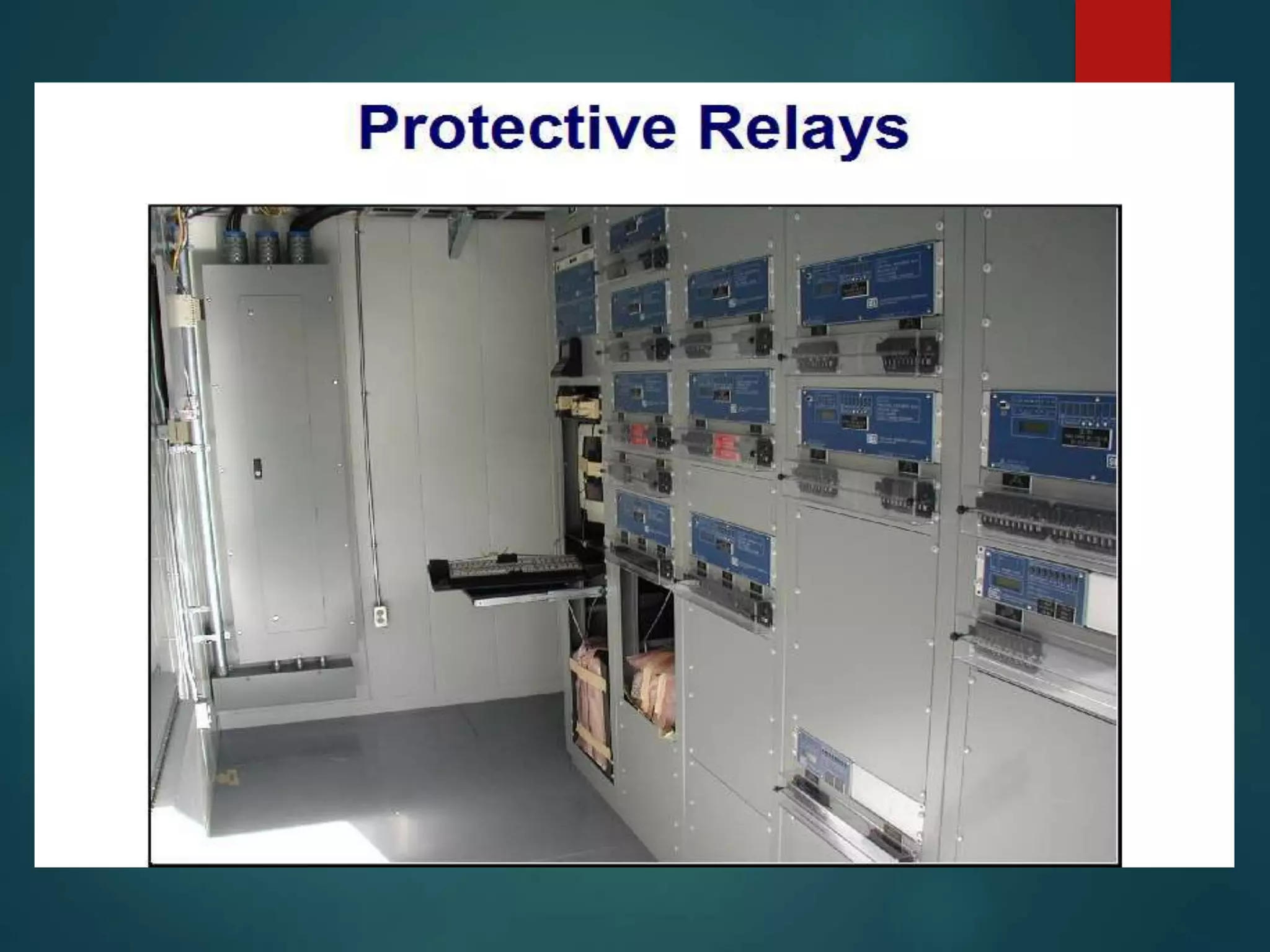
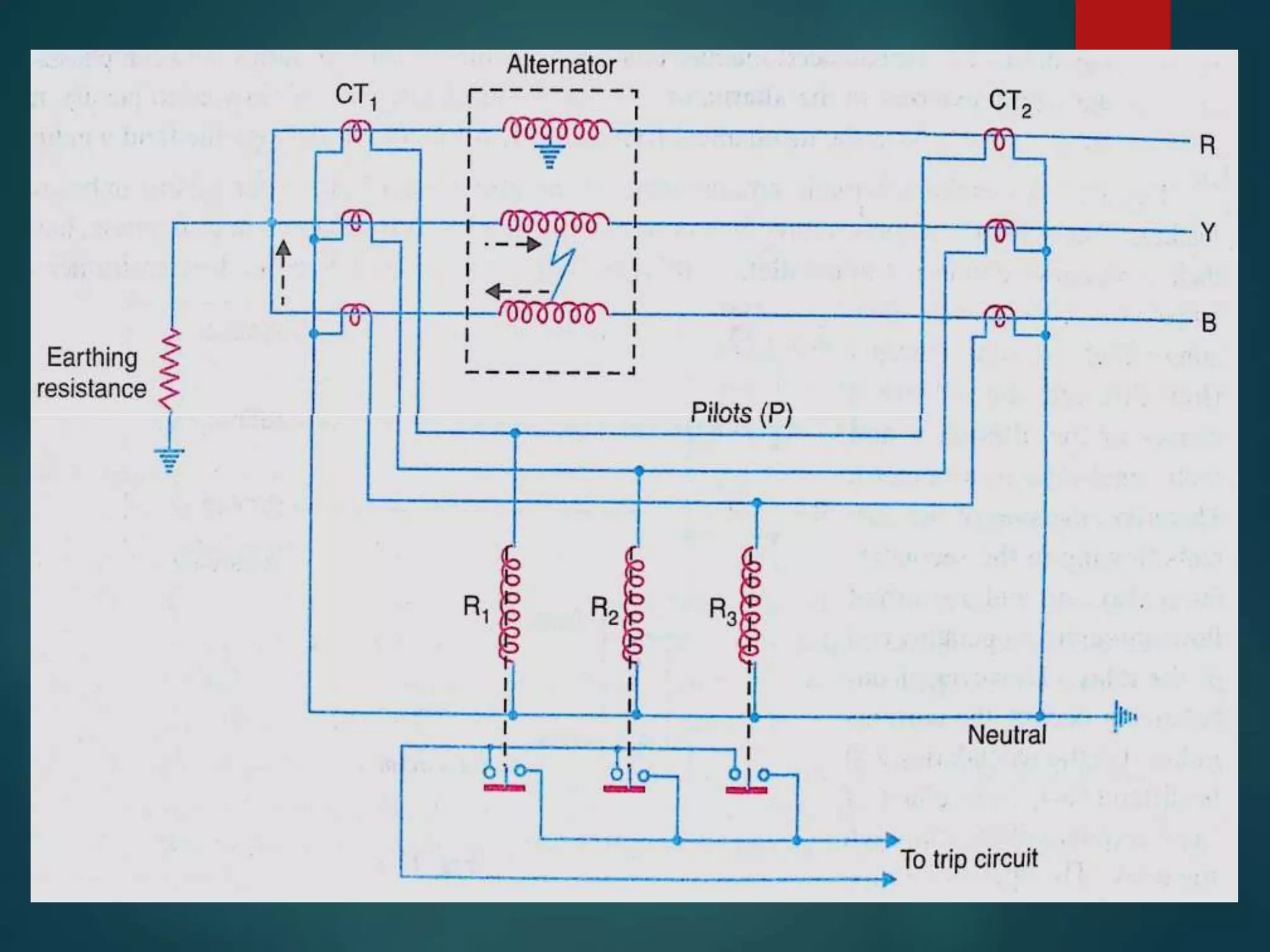
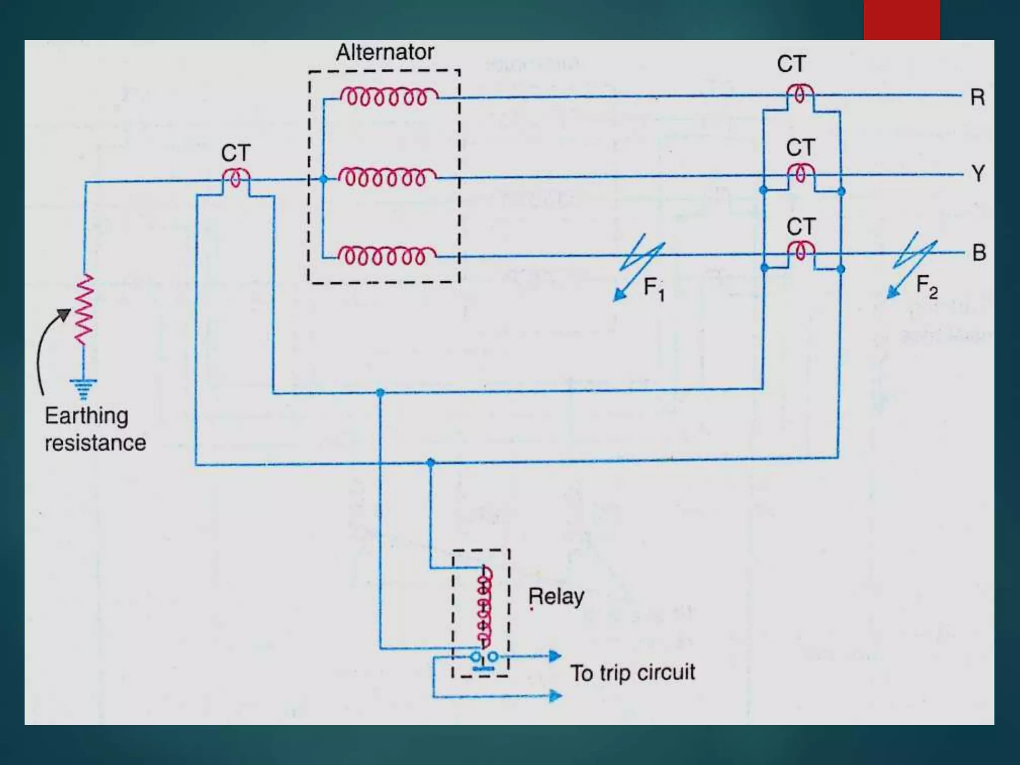
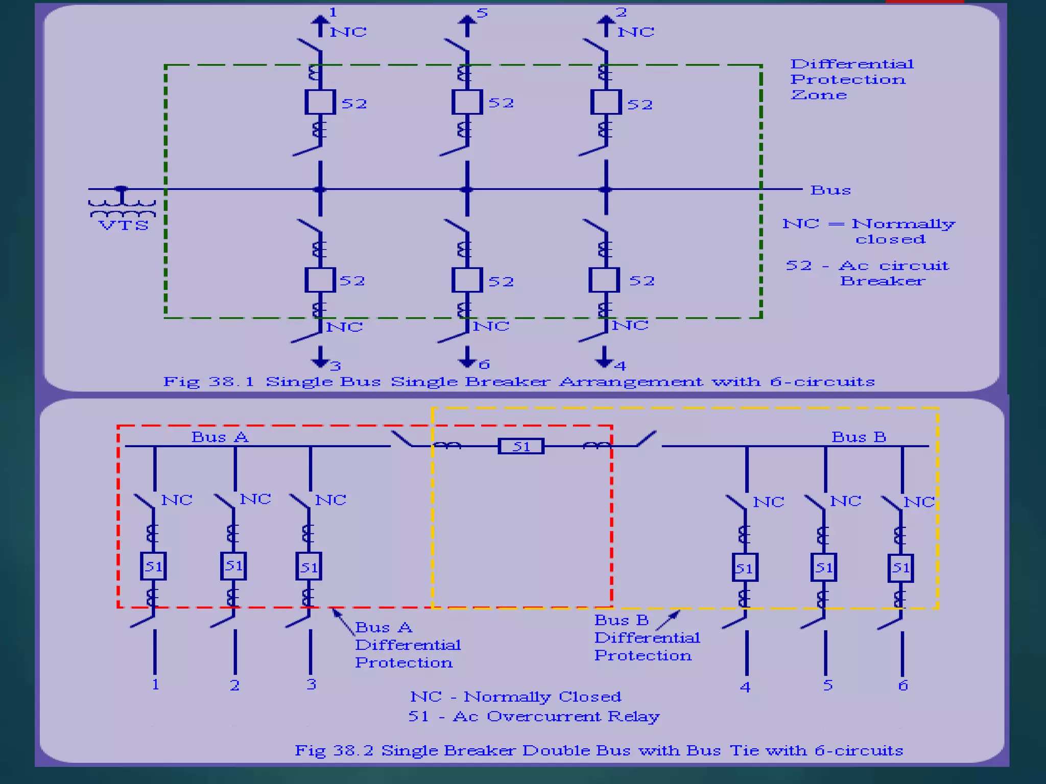
Presented to;
prof. dr. aslam Pervez MEMON
BY;
AKBAR ALI
16EL50
Power System Protection
OUTLINE
 System protection-Definition
 Need for the protection
 Elements of the protection system
 Component to be protected
What is System protection?
 System protection is the art and science of detecting
problems with power system components and isolating
these components.
Need for the protection
 The power system must maintain acceptable operation
24 hours a day
 Voltage and frequency must stay within certain limits
 Protect the public
 Improve system stability
 Minimize damage to equipment
 Protect against overloads
Damage to Main Equipment
COMPONENTS USED FOR
PROTECTION
Components to be protected
 Generators
 Transformers
 Lines
 Buses
GENERATOR
PROTECTION Failure of Prime-mover
 Failure of Field
 Over-current
 Over-speed
 Over-voltage
 Unbalanced Loading
 Stator Winding Faults
UNBALANED LOADING
 Unbalanced loading arises from fault to earth or faults
between phases on the circuits external to the
alternator.
 Unbalanced current may burn the mechanical fixing of
the rotor core or damage the field winding.
OPERATION
 Under normal operating condition, algebraic sum of
three currents flowing through the relay is zero and
relay does not operate.
 When unbalancing occur, resultant current flows
through the relay and relay trips the circuit breaker to
disconnect the alternator from the system.
STATOR WINDING
FAULTS
 Fault between phase and
 ground
 Fault between phases
 Inter-turn faults involving turns
of same phase winding
Differential Protection
 It provides protection against phase to phase and
phase to ground
 Current at two ends of the protected sections are
compared
 Under normal operating conditions, these currents are
equal, hence no current flows through the relay.
 When a fault occurs in the protected zone, currents at
two ends of the CT becomes unequal. Differential
current flowing the the relay isolates the protected
section from the system.
DIFFICULTY AND REMEDY
 In most of the cases, alternator is located at a
considerable distance from the switchgear.
 the relays are located close to the circuit breaker,
balancing resistances are inserted in shorter length of
pilot wire to balance the impedance on both side of the
relay.
Balanced earth fault protection
 Balanced earth fault protection is used for those
alternators in which neutral ends of the three phase
are connected internally to a single terminal.
 It provides no protection against phase to phase fault.
TRANSFORMER PROTECTION
 What can go wrong?
 ● Winding-to-winding faults
 ● Winding-to-ground faults
 ● Bushing faults
 Protection Methods:
 Fuse
 Differential
 Buchholz relay
Fuses
 Fuses commonly protect small distribution
transformers typically up to ratings of 1MVA at
distribution voltages. In many cases no circuit breaker
is provided, making fuse protection the only available
means of automatic isolation.
 The fuse must have a rating well above the maximum
transformer load current to withstand the short duration
overloads that may occur. Also, the fuses must
withstand the magnetising inrush currents drawn when
power transformers are energized.
Differential protection
 Current transformers on the primary and secondary
sides are connected to form a circulating current
system.
BUCHHOLZRELAY
 It is a gas actuated relay. When a fault develops
slowly, it produces heat, thereby decomposing solid or
liquid insulating material in the transformer.
 The decomposition of the insulating material produces
inflammable gases. The Buchholz relay gives an alarm
when a specified amount of gas is formed.
 The analysis of the gas collected in the relay chamber
indicates the type of the incipient fault.
WORKING
 • When an incipient fault such as a winding-to-core fault or an inter-turn fault
occurs on the transformer winding, there is severe heating of the oil.
 • This causes gases to be liberated from the oil around 350°C. There is a
build-up of oil pressure causing oil to rush into the conservator.
 • A vane is placed in the path of surge of oil between the transformer and the
conservator. A set of contacts, operated by this vane, is used as trip
contacts of the Buchholz relay. This output of Buchholz relay may be used to
trip the transformer.
TRANSMISSION LINE
PROTECTION
 What Can Go Wrong?
 FAULTS (Short Circuits)
 SOME CAUSES OF FAULTS:
 Trees
 Lightning
 Animals (birds, squirrels, snakes)
 Weather (wind, snow, ice)
 Natural Disasters (earthquakes, floods)
 Faulty equipment (switches, insulators, clamps, etc.)
 How Do We Protect Transmission Lines?
 Overcurrent
 Bi-Directional Overcurrent
 Distance (Impedance)
 Line Current Differential
BUS-BAR PROTECTION
Power system protection

Power system protection

  • 2.
    Presented to; prof. dr.aslam Pervez MEMON BY; AKBAR ALI 16EL50
  • 3.
  • 4.
    OUTLINE  System protection-Definition Need for the protection  Elements of the protection system  Component to be protected
  • 5.
    What is Systemprotection?  System protection is the art and science of detecting problems with power system components and isolating these components.
  • 6.
    Need for theprotection  The power system must maintain acceptable operation 24 hours a day  Voltage and frequency must stay within certain limits  Protect the public  Improve system stability  Minimize damage to equipment  Protect against overloads
  • 7.
    Damage to MainEquipment
  • 8.
  • 13.
    Components to beprotected  Generators  Transformers  Lines  Buses
  • 14.
    GENERATOR PROTECTION Failure ofPrime-mover  Failure of Field  Over-current  Over-speed  Over-voltage  Unbalanced Loading  Stator Winding Faults
  • 15.
    UNBALANED LOADING  Unbalancedloading arises from fault to earth or faults between phases on the circuits external to the alternator.  Unbalanced current may burn the mechanical fixing of the rotor core or damage the field winding.
  • 17.
    OPERATION  Under normaloperating condition, algebraic sum of three currents flowing through the relay is zero and relay does not operate.  When unbalancing occur, resultant current flows through the relay and relay trips the circuit breaker to disconnect the alternator from the system.
  • 18.
    STATOR WINDING FAULTS  Faultbetween phase and  ground  Fault between phases  Inter-turn faults involving turns of same phase winding
  • 19.
    Differential Protection  Itprovides protection against phase to phase and phase to ground  Current at two ends of the protected sections are compared  Under normal operating conditions, these currents are equal, hence no current flows through the relay.  When a fault occurs in the protected zone, currents at two ends of the CT becomes unequal. Differential current flowing the the relay isolates the protected section from the system.
  • 21.
    DIFFICULTY AND REMEDY In most of the cases, alternator is located at a considerable distance from the switchgear.  the relays are located close to the circuit breaker, balancing resistances are inserted in shorter length of pilot wire to balance the impedance on both side of the relay.
  • 23.
    Balanced earth faultprotection  Balanced earth fault protection is used for those alternators in which neutral ends of the three phase are connected internally to a single terminal.  It provides no protection against phase to phase fault.
  • 25.
  • 26.
     What cango wrong?  ● Winding-to-winding faults  ● Winding-to-ground faults  ● Bushing faults  Protection Methods:  Fuse  Differential  Buchholz relay
  • 27.
    Fuses  Fuses commonlyprotect small distribution transformers typically up to ratings of 1MVA at distribution voltages. In many cases no circuit breaker is provided, making fuse protection the only available means of automatic isolation.  The fuse must have a rating well above the maximum transformer load current to withstand the short duration overloads that may occur. Also, the fuses must withstand the magnetising inrush currents drawn when power transformers are energized.
  • 29.
    Differential protection  Currenttransformers on the primary and secondary sides are connected to form a circulating current system.
  • 30.
    BUCHHOLZRELAY  It isa gas actuated relay. When a fault develops slowly, it produces heat, thereby decomposing solid or liquid insulating material in the transformer.  The decomposition of the insulating material produces inflammable gases. The Buchholz relay gives an alarm when a specified amount of gas is formed.  The analysis of the gas collected in the relay chamber indicates the type of the incipient fault.
  • 32.
    WORKING  • Whenan incipient fault such as a winding-to-core fault or an inter-turn fault occurs on the transformer winding, there is severe heating of the oil.  • This causes gases to be liberated from the oil around 350°C. There is a build-up of oil pressure causing oil to rush into the conservator.  • A vane is placed in the path of surge of oil between the transformer and the conservator. A set of contacts, operated by this vane, is used as trip contacts of the Buchholz relay. This output of Buchholz relay may be used to trip the transformer.
  • 33.
  • 34.
     What CanGo Wrong?  FAULTS (Short Circuits)  SOME CAUSES OF FAULTS:  Trees  Lightning  Animals (birds, squirrels, snakes)  Weather (wind, snow, ice)  Natural Disasters (earthquakes, floods)  Faulty equipment (switches, insulators, clamps, etc.)
  • 36.
     How DoWe Protect Transmission Lines?  Overcurrent  Bi-Directional Overcurrent  Distance (Impedance)  Line Current Differential
  • 37.