SlideShare a Scribd company logo
1 of 32
Week-01 - Experiment no: 01
AIM: Identify various fuse sets viz., HRC, DO, 33KV fuse set, etc.
1. HRC (High Rupturing Capacity) Fuse
HRC Fuse has high rupturing capacity, a special method of arc extinguishing used in HRC fuse.
The construction of HRC fuse is done using a high heat-resistant component such as ceramic
where metal finished are caps are attached to this body. Through silver-current, the ceramic
body and metal caps are connected.
The inner section of the fuse is filled with a powder material which is made up of materials
like chalk, plaster of Paris, marble, quartz, and many others. The chemical reaction which
happens between the silver vapor and filled powder will produce a high-
end resistance substance where helps in reducing the arc present in the fuse.
2. D.O (DROP OUT) Fuse
The fiberglass tubes are employed as the fuse carriers in drop out fuses. The either terminal
are tinned heavily with nonferrous materials. The connection and cleaning actions are
performed by the phosphorus bronze brush type contacts.
The material used in drop out fuses should possess lower resistance as well as lower melting
points, drop-out High voltage fuse (33KV) mounting plate is fixed in the middle of the support
insulator. Support insulator has the upper and lower terminals for the connection wire.
3. Horn Gap Fuses
Horn-Gap Fuse sets are of 11KV,22KV & 33KV voltage class, outdoor, vertically mounted
are required for protection of transformers and tapping points. Rated current of Horn-
Gap fuse sets shall be 50A/100A/200A/400A. Insulator of H.G Fuse shall be Porcelain
(Pin/Post type)/ Solidcore /Polymeric type
4. Kit Kat Fuse
Porcelain type kit kat Fuse Flush type kit kat Fuse
Kit Kat Fuse is a semi-enclosed fuse also considered as rewireable fuse designed mainly
for the domestic wiring and small-scale usage.
5. Automotive Fuse
Automotive Fuse (Blade fuse type) used to protect the electrical components and devices
of vehicle. They act as a safety measure to protect from overcurrent of an electrical circuit.
Its basic purpose is to break the circuit when the current becomes more than the desired
value, thereby preventing possible damage from equipment failures and short circuits.
Week-01 - Experiment no: 02 (a)
AIM: Measure and select the appropriate size of fuse wire.
Standard fuse SWG table for the fuse elements used in this type are tinned copper wire, lead
and tin alloy or aluminium wire.
PROCEDURE:
1. Measure the gauge of given fuse wire/element using SWG.
2. Observer the Standard fuse SWG Table & Write down the Current rating
in Observation Table.
3. Repeat the above procedure for the different fuse wire/elements.
OBSERVATION TABLE:
SL. No
Fuse wire gauge
in S.W.G
Current rating as per the Standard table
in Amps
CONCLUSION:
Week-01 - EXPERIMENT NO: 2(b)
AIM: Test the HRC fuse by performing a Load test.
APPARATUS REQUIRED:
Sl. No Apparatus Range Quantity
1. HRC Fuse 2A 01
2. Voltmeter (A.C) 0-500V 01
3. Ammeter (A.C) 0-10A 01
4. S.P.S.T Switch ----------- 01
5. Lamp Load 0-2KW / 10 Amps 01
6. Patch Chords 1 Sq.mm As Required
CIRCUIT DIAGRAM:
OBSERVATION TABLE:
Sl.No Load Current
in Amps
Current through HRC Fuse element
in Amps
Time of Operation
in Seconds
PROCEDURE:
1. Connections are made as per the circuit diagram.
2. Keep all the Load Switches in OFF position & Keep the SPST switch in Close
Position.
3. Now Switch ON the Main supply, Observe the Voltmeter reading &
confirm for rated voltage (1Ø- 230V).
4. Now switch ON the Loads in Stepwise, Observe the Load Current &
Increase the load current up to more than 2 times of HRC Fuse current
rating.
5. Now Open the SPST switch as well as start the STOP WATCH (Timmer).
6. Note down the Load current & HRC fuse Blows time.
7. Switch OFF the main Supply & Disconnect the circuit.
CONCLUSION:
Week- 02 - EXPERIMENT NO: 1(a)
AIM: Identify the various types of CB- MCB, ELCB, RCCB, MPCB and MCCB.
Trace and locate MCBs used in your institution and note down their
specifications.
I. Identify the various types of CB- MCB, ELCB, RCCB, MPCB and MCCB.
MCB - Miniature Circuit Breakers. ELCB - Earth-leakage circuit breaker
RCCB - Residual Current Circuit Breaker MPCB- Motor Protection Circuit Breaker
MCCB - Moulded Case Circuit Breaker
II. Trace and locate MCBs used in your institution and note down their specifications.
MCB
Place2: Place2: Place3:
Specification
Parameters
Ranges Ranges Ranges
Standard Conformity
Standard Rated
Current (In)
Type of Curve
Poles
Rated Short Circuit
Breaking Capacity (Icn)
Rated Voltage (Ue)
Rated Frequency(f)
Rated Insulation
Voltage (Ui)
Ambient Temperature
Contact indication
mounting mode &
mounting support
Week- 02 - EXPERIMENT NO: 01(b)
AIM: Dismantle MCCB or ELCB and identify various parts.
Week- 02 - EXPERIMENT NO: 01(c)
AIM: Test the MCB and plot its inverse time characteristic curve.
APPARATUS REQUIRED:
Sl.No Apparatus Range Quantity
1. M.C.B Fuse (Single Pole) 2A 01
2. Voltmeter (A.C) 0-500V 01
3. Ammeter (A.C) 0-10A 01
4. S.P.S.T Switch ----------- 01
5. Lamp Load 0-2KW / 10 Amps 01
6. Patch Chords 1 Sq.mm As Required
CIRCUIT DIAGRAM:
OBSERVATION TABLE:
Sl.No Load Current
in Amps
Time of Operation
in Seconds
1.
2.
3.
4.
5.
PROCEDURE:
1. Connections are made as per the circuit diagram.
2. Keep all the Load Switches in OFF position & Keep the SPST switch in Close
Position.
3. Now Switch ON the Main supply, Observe the Voltmeter reading &
confirm for rated voltage (1Ø- 230V).
4. Now switch ON the Loads in Stepwise, Observe the Load Current &
Increase the load current up to more than 2 times of MCB current rating.
5. Now Open the SPST switch as well as start the STOP WATCH (Timmer).
6. Note down the Load current & MCB Trip time.
7. Repeat the Steps No. 4, 5 & 6 for different load currents.
8. Switch OFF the main Supply & Disconnect the circuit.
NATURE OF GRAPH:
CONCLUSION:
Week- 02 - EXPERIMENT NO: 02(a)
AIM: Troubleshooting and servicing of LT circuit breaker.
Troubleshooting of LT circuit breaker: Causes & Remedies
1. Identify Tripped Circuit Breaker
Circuit breaker emits a humming sound when it is overloaded but has not switched off yet.
Inside electric access panel, the tripped breaker lever can usually be found between the “on”
and “off” position
2. Test Circuit Breaker
Check the lever by moving it from ‘on’ to ‘off’ a couple of times to check how loose it is. If
breaker has no ‘give’ and moves easily then it is faulty and you need to have it replaced as
soon as possible.
3. Switch Off All of Appliances Again
Switch off all appliances that are connected to circuit breaker but make sure to do it all at
once to prevent a surge of electrical power when you reset it. If circuit breaker keeps on
tripping then hire a professional to come and have a look at it.
4. Check Wiring
If home has faulty wiring, then circuit breaker will be tripping continuously and you may find
yourself receiving electrical shocks when powering certain appliances. This requires a trained
professional so don’t try this on own. Simply identify the problem and hire a professional to
take care of it.
5. Have Circuit Breaker Tested for the Necessary Voltage
Touch one probe of the 120–240-volt tester to the tip of the “hot” wire, while touching the
other tip to a bare copper grounding wire within the main electrical box. Use a neutral
grounding terminal which is secured with ground wires and neutral wires for the probe. You
will need to replace circuit breaker if you find the right amount of voltage present.
Servicing steps of LT circuit breaker.
1. Evaluate, Clean, Service and Test
2. Insulating parts which include bushings should be wiped down and
cleaned
3. Check fault operations.
4. Trip Testing to ensure manufacturer standards
5. Inspection of alignment conditions and stationary contacts
6. Remove damaged parts
7. Reset breaker operation mechanism to manufacturer’s instruction book
8. Primary and Secondary Testing
9. On Site Evaluation of breakers, bus ducts, and fuses
Week- 02 - EXPERIMENT NO: 02(b)
AIM: Test commercially available ACCL.
APPARATUS REQUIRED:
Sl.No Apparatus Range Quantity
1. A.C.C.L 32A 01
2. Voltmeter (A.C) 0-500V 01
5. Lamp Load 0-2KW / 10 Amps 01
6. Patch Chords 1 Sq.mm As Required
CIRCUIT DIAGRAM:
OBSERVATION TABLE:
CURRENT LIMIT setting: _________Amps
Sl.
No
E.B
D.P switch
D.G
D.P switch
Load
Switch’s
A.C.C.L Actions
1 ON OFF ON
2 OFF ON ON
3 ON ON ON
4 OFF ON TRIP
PROCEDURE:
1. Connections are made as per the circuit diagram.
2. Keep all the Load Switches in OFF position.
3. Now Switch ON the Main supply, Switch ON the EB Side DP switch &
observe the lamp Load by Switch ON the loads in Steps.
4. Now switch OFF the EB side DP switch & Switch ON the DG side DP.
5. Switch ON the Loads in Stepwise, Observe the Load Current & Increase
the load current up to more than CURRENT LIMIT setting.
6. Observe the Results as per the Observation Table & write down the
Actions by the ACCL.
7. Switch OFF the main Supply & Disconnect the circuit.
CONCLUSION:
Week-03 - EXPERIMENT NO: 1
AIM: Visit to Substation.
a. Identify the parts of circuit breaker and check its operation.
b. Demonstrate test tripping characteristic of circuit breaker for over
current and short circuit current.
Parts of Circuit Breaker
Week-03 - EXPERIMENT NO: 2
AIM: a. Demonstrate Installation operation and maintenance of SF6 circuit
breaker, Vacuum circuit breaker.
b. Carry out timer test on circuit breakers.
c. Demo on RMU
Week-04 - EXPERIMENT NO: 1
AIM: a. Demonstrate various parts of the relay and ascertain the operation.
b. Demonstrate setting of pick-up current/ time setting multiplier for
relay operation
Pick Up Current of Relay:
In all electrical relays, the moving contacts are not free to move. All the contacts remain in
their respective normal position by some force applied to them continuously. This force is
called the controlling force of the relay. This controlling force may be the gravitational force,
may be a spring force, or may be a magnetic force.
The force applied to the relay’s moving parts for changing the normal position of the contacts
is called deflecting force. This deflecting force is always in opposition of controlling force and
is present always in the relay. The current for which the relay initiates its operation is called
pick up current of relay.
Current Setting of Relay:
The minimum pick up value of the deflecting force of an electrical relay is constant. Again, the
deflecting force of the coil is proportional to its number of turns and current flowing through
the coil. Now, if we can change the number of active turns of any coil, the required current to
reach at minimum pick value of the deflecting force, in the coil also changes.
The current setting of relay is expressed in percentage ratio of relay pick up current to rated
secondary current of CT.
Plug Setting Multiplier of Relay:
Plug setting multiplier of relay is referred as ratio of fault current in the relay to its pick up
current.
Suppose we have connected on protection CT of ratio 200/1 A and current setting is 150%.
Hence, pick up current of the relay is, 1 × 150 % = 1.5 A
Now, suppose fault current in the CT primary is 1000 A. Hence, fault current in the CT
secondary, i.e., in the relay coil is, 1000 × 1/200 = 5A
Therefore PSM of the relay is, 5 / 1.5 =3.33
Time Setting Multiplier of Relay:
The operating time of an electrical relay mainly depends upon two factors :
• How long distance to be travelled by the moving parts of the relay for closing relay
contacts and
• How fast the moving parts of the relay cover this distance.
So far by adjusting relay operating time, both of the factors to be adjusted. The adjustment
of traveling distance of an electromechanical relay is commonly known as time setting. This
adjustment is commonly known as time setting multiplier of relay. The time setting dial is
calibrated from 0 to 1 in steps of 0.05 sec.
Hence, actual operating time of the relay is 3 × 0.1 = 0.3 sec. i.e. 10% of 3 sec.
Week-04 - EXPERIMENT NO: 2(a)
AIM: Test the Earth Leakage Relay.
APPARATUS REQUIRED:
Sl.No Apparatus Range Quantity
1. Earth Leakage Relay kit Digital type 01
2. C.B.C.T with Lamp load --- 01
3. Patch Chords 1 Sq.mm As Required
CIRCUIT DIAGRAM:
OBSERVATION TABLE:
Leakage Current Setting: _________Amps
Sl. No
Lamp load Circuit
Conditions
Leakage Current
In Amps
Trip Circuit
1 Normal
2 Earth Leakage fault
PROCEDURE:
1. Connections are made as per the circuit diagram.
2. Keep all the Load Switches in OFF position.
3. Now Switch ON the Main supply, Switch ON the lamps under normal
condition.
4. Now switch OFF Lamp load, main supply & alter the circuit as the current
leakage to earth.
5. Switch ON the main supply, Lamp load & Observe the Load leakage
current & Trip condition.
6. Observe the Results & Note down in the Observation table.
7. Switch OFF the main Supply & Disconnect the circuit
CONCLUSION:
Week-04 - EXPERIMENT NO: 2(b)
AIM: Test the Electromechanical over voltage relay.
APPARATUS REQUIRED:
Sl.No Apparatus Range Quantity
1. Electromechanical over voltage
relay kit
Electromechanical
type
01
2. Patch Chords 1 Sq.mm As Required
CIRCUIT DIAGRAM:
OBSERVATION TABLE:
Plug Setting (PS) : _________ Volts,
Sl.
No
Plug Setting
Multiplier (PSM)
Applied Voltage
= PS × PSM
in Volts
TSM: TSM:
Operating Time
in Seconds
Operating Time
in Seconds
1
2
3
4
5
6
PROCEDURE:
1. Connections are made as per the circuit diagram.
2. Make the Settings of PS as per the decide value & keep all the Load
Switches in OFF position.
3. Now Switch ON the Main supply & Apply the Calculated Applied voltage.
4. Now reset the relay, if it is operated then Confirm the Disc Halt on
Position.
5. Switch to Set Position, Observe Timmer & Trip condition.
6. Note down the Operating Time in the Observation table.
7. Repeat the Steps 4 , 5 & 6 for different PMS, Applied Voltage & TSM.
8. Switch OFF the main Supply & Disconnect the circuit
NATURE GRAPH:
CONCLUSION:
Week-05 - EXPERIMENT NO: 1
AIM: Test the Static Over Voltage and Under Voltage Relay and Plot its
inverse time – Voltage Characteristics.
APPARATUS REQUIRED:
Sl.No Apparatus Range Quantity
1. Static / Microprocessor Over
Voltage and Under Voltage Relay kit
Microprocessor
type
01
2. Patch Chords 1 Sq.mm As Required
CIRCUIT DIAGRAM:
OBSERVATION TABLE:
For Over Voltage (OV)
% age of over Voltage = _______ %
Pick up Voltage (Vs) = 1 + (0.05 + Σ a) Vn Volts
= ________________________ Volts, Where Vn=110V
Voltage Set switch Value (Σa) =
Sl.
No
Applied Voltage
in Volts
Operating Time
in Seconds
1
2
3
4
5
For Under Voltage (UV)
% age of over Voltage = _______ %
Pick up Voltage (Vs) = 1 - (0.05 + Σa) Vn Volts
= ________________________ Volts, Where Vn=110V
Voltage Set switch Value (Σa) =
Sl.
No
Applied Voltage
in Volts
Operating Time
in Seconds
1
2
3
4
5
PROCEDURE:
1. Connections are made as per the circuit diagram.
2. Make the Switch Settings as per Requirement like OV/UV.
3. Decide the %age of OV/UV, accordingly calculate the Vs.
4. Now make the Switch Settings of Vs as per the Value of Σa.
5. Switch ON the Main supply & apply the different voltages (OV/UV).
6. Observe the Timmer, Trip condition, note down the Operating Time &
Voltage in the Observation table.
7. Reset the relay & repeat the step No. 6 for different Voltages (UV/OV).
8. Switch OFF the main Supply & Disconnect the circuit.
NATURE GRAPH:
CONCLUSION:
Week-05 - EXPERIMENT NO: 2(a)
AIM: Program and test the Numerical Over Current for definite Time operations.
APPARATUS REQUIRED:
Sl.No Apparatus Range Quantity
1. Numerical / Digital Over Current Relay Kit
Digital Over
Current type
01
2. Patch Chords 1 Sq.mm As Required
CIRCUIT DIAGRAM:
OBSERVATION TABLE:
Sl.
No
Set Current
in Amps
Set definite Time
in Seconds
Operating Current
in Amps
Operating Time
in Seconds
1
2
3
PROCEDURE:
1. Connections are made as per the circuit diagram.
2. Switch ON the Main supply.
3. Set the Current & Time as per the operation procedure of relay.
4. Switch OFF & Switch ON the Main supply then apply the Current more
than the Set Value using current source.
5. Now Switch to Starts operation & Observe the Timmer, Trip condition,
note down the Operating Time & Current in the Observation table.
6. Set the relay for different Current & Time.
7. Repeat the steps No. 4 & 5.
8. Switch OFF the main Supply & Disconnect the circuit.
NATURE GRAPH:
CONCLUSION:
Week-06 - EXPERIMENT NO: 01
AIM: Test the operation of Buchholz Relay.
APPARATUS REQUIRED:
Sl.No Apparatus Range Quantity
1. Buchholz Relay Kit -- 01
2. Transformer oil -- 5 Litters
3. Patch Chords 1 Sq.mm As Required
EXPERIMENTAL DIAGRAM:
OBSERVATION TABLE:
Sl.
No
Air Pump Trip Circuit
1 OFF
2 ON
PROCEDURE:
1. Make sure the transformer tank and relay are filled with oil and there is
some oil in conservator tank, the air valve of the Buchholz relay must be
closed.
2. Now turn ON the air Pump and the air bubbles starts blowing into the
Buchholz relay. The Air Pump is fitted with a non-return valve to protect
the compressor by reverse flow of oil.
3. Notice the relays trips after some time of air flow & simultaneously to the
air pump is cut OFF.
4. Turn OFF the Air Pump switch and then release the air valve on the
Buchholz relay.
CONCLUSION:
Week - 06 - EXPERIMENT NO: 02
AIM: Conduct BDVT on Transformer oil.
Sl.No Apparatus Range Quantity
1. BDVT on Transformer oil Kit 0-60KV / 1KVA 01
2. Transformer oil -- 1 Litters
3. Patch Chords 1 Sq.mm As Required
EXPERIMENTAL DIAGRAM:
OBSERVATION TABLE:
Sl.
No
Distance of Electrodes
in mm
Breakdown Voltage
in KV
1 2.5
2 4
3
PROCEDURE:
1. Adjust the gap between electrodes to 2.5mm/4mm by the guage.
2. Fill the cup with oil and place it on the H.T electrodes. Close the hood
properly, so as to operate the interlock microswitch which acts as a safety
precaution for the operator.
3. Switch ON the main supply, the corresponding lamp will glow.
4. Press the H.T ON push Button the contactor will operate and H.T ON lamp
will glow. If the contactor does not operate, it means that the Variac brush
arm is not at zero position OR the Hood interlock microswitch is not closed
as mentioned in ‘step 2’. The zero interlocking od the variac is another
safety feature against switching on the unit directly at a higher voltage.
This will be indicated by the Voltmeter reading also.
5. Raise the voltage by turning the variac knob in clockwise direction. In case
the oil sample fails the unit will trip to lower down the voltage turn the
variac knob anti-clock and bring it to zero position before start of further
tests.
CONCLUSION:

More Related Content

What's hot

REPORT ON 33/11KV SUBSTATION
REPORT ON 33/11KV SUBSTATION REPORT ON 33/11KV SUBSTATION
REPORT ON 33/11KV SUBSTATION Ravi Phadtare
 
Week-05 -Design a GA LT panel wiring--.pptx
Week-05 -Design a GA LT panel wiring--.pptxWeek-05 -Design a GA LT panel wiring--.pptx
Week-05 -Design a GA LT panel wiring--.pptxPremanandDesai
 
Week - 09 - Testing of CB & Substation Earthing
Week - 09 - Testing of CB & Substation Earthing Week - 09 - Testing of CB & Substation Earthing
Week - 09 - Testing of CB & Substation Earthing PremanandDesai
 
final year project report
final year project reportfinal year project report
final year project reportAnuj Kumar
 
Distribution boards and Protection devices ppt
Distribution boards and Protection devices  pptDistribution boards and Protection devices  ppt
Distribution boards and Protection devices pptZuhairQadri
 
Representation of power system components
Representation of power system componentsRepresentation of power system components
Representation of power system componentsPrasanna Rao
 
Presentation on Power Transformer
Presentation on Power TransformerPresentation on Power Transformer
Presentation on Power TransformerAjay Maurya
 
Basic short circuit calculation procedure
Basic short circuit calculation procedureBasic short circuit calculation procedure
Basic short circuit calculation procedureMustafa Ismail
 
industrial Training report in PTCUL Substation dehradun
industrial Training report in PTCUL Substation dehradunindustrial Training report in PTCUL Substation dehradun
industrial Training report in PTCUL Substation dehradunsurendra rawat
 
OPERATION & MAINTENANCE OF 33/11 kV SUBSTATION AT DHAKA PALLI BIDYUT SAMITY-1
OPERATION & MAINTENANCE OF 33/11 kV SUBSTATION AT DHAKA PALLI BIDYUT SAMITY-1OPERATION & MAINTENANCE OF 33/11 kV SUBSTATION AT DHAKA PALLI BIDYUT SAMITY-1
OPERATION & MAINTENANCE OF 33/11 kV SUBSTATION AT DHAKA PALLI BIDYUT SAMITY-1md muzahidul haque
 
Protection of transformer
Protection of transformerProtection of transformer
Protection of transformerSumeet Ratnawat
 
33/11 kV substation (u.p.p.c.l.)
33/11 kV substation (u.p.p.c.l.)33/11 kV substation (u.p.p.c.l.)
33/11 kV substation (u.p.p.c.l.)Prateek Agarwal
 
Maintenance schedule of Substation.
Maintenance schedule of Substation.Maintenance schedule of Substation.
Maintenance schedule of Substation.Sheikh Nazmul Islam
 

What's hot (20)

REPORT ON 33/11KV SUBSTATION
REPORT ON 33/11KV SUBSTATION REPORT ON 33/11KV SUBSTATION
REPORT ON 33/11KV SUBSTATION
 
Week-05 -Design a GA LT panel wiring--.pptx
Week-05 -Design a GA LT panel wiring--.pptxWeek-05 -Design a GA LT panel wiring--.pptx
Week-05 -Design a GA LT panel wiring--.pptx
 
Lec # 07 parallel operation of synchronous generators
Lec # 07 parallel operation of synchronous generatorsLec # 07 parallel operation of synchronous generators
Lec # 07 parallel operation of synchronous generators
 
Week - 09 - Testing of CB & Substation Earthing
Week - 09 - Testing of CB & Substation Earthing Week - 09 - Testing of CB & Substation Earthing
Week - 09 - Testing of CB & Substation Earthing
 
Relays
  Relays  Relays
Relays
 
final year project report
final year project reportfinal year project report
final year project report
 
Distribution boards and Protection devices ppt
Distribution boards and Protection devices  pptDistribution boards and Protection devices  ppt
Distribution boards and Protection devices ppt
 
Neutral grounding
Neutral groundingNeutral grounding
Neutral grounding
 
Tap Changer
Tap ChangerTap Changer
Tap Changer
 
Representation of power system components
Representation of power system componentsRepresentation of power system components
Representation of power system components
 
Presentation on Power Transformer
Presentation on Power TransformerPresentation on Power Transformer
Presentation on Power Transformer
 
Basic short circuit calculation procedure
Basic short circuit calculation procedureBasic short circuit calculation procedure
Basic short circuit calculation procedure
 
industrial Training report in PTCUL Substation dehradun
industrial Training report in PTCUL Substation dehradunindustrial Training report in PTCUL Substation dehradun
industrial Training report in PTCUL Substation dehradun
 
OPERATION & MAINTENANCE OF 33/11 kV SUBSTATION AT DHAKA PALLI BIDYUT SAMITY-1
OPERATION & MAINTENANCE OF 33/11 kV SUBSTATION AT DHAKA PALLI BIDYUT SAMITY-1OPERATION & MAINTENANCE OF 33/11 kV SUBSTATION AT DHAKA PALLI BIDYUT SAMITY-1
OPERATION & MAINTENANCE OF 33/11 kV SUBSTATION AT DHAKA PALLI BIDYUT SAMITY-1
 
Protection of transformer
Protection of transformerProtection of transformer
Protection of transformer
 
BUS BAR PROTECTION PPT BY:-R.K.PANDIT
BUS BAR  PROTECTION PPT BY:-R.K.PANDITBUS BAR  PROTECTION PPT BY:-R.K.PANDIT
BUS BAR PROTECTION PPT BY:-R.K.PANDIT
 
Full transformer
Full transformerFull transformer
Full transformer
 
Panel designing
Panel designingPanel designing
Panel designing
 
33/11 kV substation (u.p.p.c.l.)
33/11 kV substation (u.p.p.c.l.)33/11 kV substation (u.p.p.c.l.)
33/11 kV substation (u.p.p.c.l.)
 
Maintenance schedule of Substation.
Maintenance schedule of Substation.Maintenance schedule of Substation.
Maintenance schedule of Substation.
 

Similar to Switchgear and protection - lab

Protection & switchgear
Protection & switchgear   Protection & switchgear
Protection & switchgear johny renoald
 
U.C: SERVICE IGNITION SYSTEM
U.C: SERVICE IGNITION SYSTEM U.C: SERVICE IGNITION SYSTEM
U.C: SERVICE IGNITION SYSTEM Montefolka Ruel
 
Rectifier Operations & Maintenance - Don Olson - 2.4.2020
Rectifier Operations & Maintenance - Don Olson - 2.4.2020Rectifier Operations & Maintenance - Don Olson - 2.4.2020
Rectifier Operations & Maintenance - Don Olson - 2.4.2020nacetwincities
 
Electrical Installations, MCB, MCCB, ELCB
Electrical Installations, MCB, MCCB, ELCBElectrical Installations, MCB, MCCB, ELCB
Electrical Installations, MCB, MCCB, ELCBMANOJ964697
 
DIGITAL TESTING OF HIGH VOLTAGE CIRCUIT BREAKER
DIGITAL TESTING OF HIGH VOLTAGE CIRCUIT BREAKERDIGITAL TESTING OF HIGH VOLTAGE CIRCUIT BREAKER
DIGITAL TESTING OF HIGH VOLTAGE CIRCUIT BREAKERRitesh Kumawat
 
Isolator and bushing
Isolator and bushingIsolator and bushing
Isolator and bushingNovia Putri
 
Chapter 57
Chapter 57Chapter 57
Chapter 57mcfalltj
 
Electrical Installation.pptx
Electrical Installation.pptxElectrical Installation.pptx
Electrical Installation.pptxbharath364108
 
Testing of c.b.(hk & hr) nihal
Testing of c.b.(hk & hr) nihalTesting of c.b.(hk & hr) nihal
Testing of c.b.(hk & hr) nihalNihal Shiroya
 
220 KV Substation Operation & Maintenance
220 KV Substation Operation & Maintenance220 KV Substation Operation & Maintenance
220 KV Substation Operation & MaintenanceHimansu Pradhan
 
Circuit Breaker and its types
Circuit Breaker and its typesCircuit Breaker and its types
Circuit Breaker and its typesRakesh Gothwal
 
CIRCUIT BREAKER USED IN THERMAL POWER PLANTS
CIRCUIT BREAKER USED IN THERMAL POWER PLANTSCIRCUIT BREAKER USED IN THERMAL POWER PLANTS
CIRCUIT BREAKER USED IN THERMAL POWER PLANTSDigantaSinha1
 
Testing of circuit breakers
Testing of circuit breakersTesting of circuit breakers
Testing of circuit breakersKabilesh K
 
Switchgear presentation
Switchgear presentationSwitchgear presentation
Switchgear presentationNadir Baloch
 
switchgearpresentation-151030171028-lva1-app6892.pptx
switchgearpresentation-151030171028-lva1-app6892.pptxswitchgearpresentation-151030171028-lva1-app6892.pptx
switchgearpresentation-151030171028-lva1-app6892.pptxDrNiveditaSingh3
 
power house training seminar
power house training seminarpower house training seminar
power house training seminarParas kumar
 
Electrical and Electronics lab manual
Electrical and Electronics lab manualElectrical and Electronics lab manual
Electrical and Electronics lab manualCyber4Tech
 

Similar to Switchgear and protection - lab (20)

Protection & switchgear
Protection & switchgear   Protection & switchgear
Protection & switchgear
 
U.C: SERVICE IGNITION SYSTEM
U.C: SERVICE IGNITION SYSTEM U.C: SERVICE IGNITION SYSTEM
U.C: SERVICE IGNITION SYSTEM
 
Rectifier Operations & Maintenance - Don Olson - 2.4.2020
Rectifier Operations & Maintenance - Don Olson - 2.4.2020Rectifier Operations & Maintenance - Don Olson - 2.4.2020
Rectifier Operations & Maintenance - Don Olson - 2.4.2020
 
Testing of cb
Testing of cbTesting of cb
Testing of cb
 
Executive summary
Executive summaryExecutive summary
Executive summary
 
Electrical Installations, MCB, MCCB, ELCB
Electrical Installations, MCB, MCCB, ELCBElectrical Installations, MCB, MCCB, ELCB
Electrical Installations, MCB, MCCB, ELCB
 
DIGITAL TESTING OF HIGH VOLTAGE CIRCUIT BREAKER
DIGITAL TESTING OF HIGH VOLTAGE CIRCUIT BREAKERDIGITAL TESTING OF HIGH VOLTAGE CIRCUIT BREAKER
DIGITAL TESTING OF HIGH VOLTAGE CIRCUIT BREAKER
 
Isolator and bushing
Isolator and bushingIsolator and bushing
Isolator and bushing
 
Chapter 57
Chapter 57Chapter 57
Chapter 57
 
Electrical Installation.pptx
Electrical Installation.pptxElectrical Installation.pptx
Electrical Installation.pptx
 
Testing of c.b.(hk & hr) nihal
Testing of c.b.(hk & hr) nihalTesting of c.b.(hk & hr) nihal
Testing of c.b.(hk & hr) nihal
 
220 KV Substation Operation & Maintenance
220 KV Substation Operation & Maintenance220 KV Substation Operation & Maintenance
220 KV Substation Operation & Maintenance
 
Circuit Breaker and its types
Circuit Breaker and its typesCircuit Breaker and its types
Circuit Breaker and its types
 
CIRCUIT BREAKER USED IN THERMAL POWER PLANTS
CIRCUIT BREAKER USED IN THERMAL POWER PLANTSCIRCUIT BREAKER USED IN THERMAL POWER PLANTS
CIRCUIT BREAKER USED IN THERMAL POWER PLANTS
 
Testing of circuit breakers
Testing of circuit breakersTesting of circuit breakers
Testing of circuit breakers
 
Switchgear presentation
Switchgear presentationSwitchgear presentation
Switchgear presentation
 
switchgearpresentation-151030171028-lva1-app6892.pptx
switchgearpresentation-151030171028-lva1-app6892.pptxswitchgearpresentation-151030171028-lva1-app6892.pptx
switchgearpresentation-151030171028-lva1-app6892.pptx
 
pe lab manual
pe lab manualpe lab manual
pe lab manual
 
power house training seminar
power house training seminarpower house training seminar
power house training seminar
 
Electrical and Electronics lab manual
Electrical and Electronics lab manualElectrical and Electronics lab manual
Electrical and Electronics lab manual
 

More from PremanandDesai

Week-11 - Assembly drawing - Synchronous Motor
Week-11 - Assembly drawing -  Synchronous Motor Week-11 - Assembly drawing -  Synchronous Motor
Week-11 - Assembly drawing - Synchronous Motor PremanandDesai
 
Week-10 - Assembly drawing - Alternators
Week-10 - Assembly drawing - AlternatorsWeek-10 - Assembly drawing - Alternators
Week-10 - Assembly drawing - AlternatorsPremanandDesai
 
Week-09 - Assembly drawing-Induction Motor
Week-09 - Assembly drawing-Induction Motor Week-09 - Assembly drawing-Induction Motor
Week-09 - Assembly drawing-Induction Motor PremanandDesai
 
Week-08 - Transformer Assembly-Threephase
Week-08 - Transformer Assembly-ThreephaseWeek-08 - Transformer Assembly-Threephase
Week-08 - Transformer Assembly-ThreephasePremanandDesai
 
Week-07- Developed Winding Diagrams - 1 phase--.pptx
Week-07- Developed Winding Diagrams - 1 phase--.pptxWeek-07- Developed Winding Diagrams - 1 phase--.pptx
Week-07- Developed Winding Diagrams - 1 phase--.pptxPremanandDesai
 
Week-06 - Developed Winding Diagrams - 3 phase--.pptx
Week-06 - Developed Winding Diagrams - 3 phase--.pptxWeek-06 - Developed Winding Diagrams - 3 phase--.pptx
Week-06 - Developed Winding Diagrams - 3 phase--.pptxPremanandDesai
 
Week-04 -Motor control Panel board
Week-04 -Motor control Panel boardWeek-04 -Motor control Panel board
Week-04 -Motor control Panel boardPremanandDesai
 
Week-03 - Electrical wiring of Residential, Hospital , small workshop
Week-03 - Electrical wiring of  Residential, Hospital , small workshopWeek-03 - Electrical wiring of  Residential, Hospital , small workshop
Week-03 - Electrical wiring of Residential, Hospital , small workshopPremanandDesai
 
Week-02 - Single line diagram of Substations
Week-02 - Single line diagram of SubstationsWeek-02 - Single line diagram of Substations
Week-02 - Single line diagram of SubstationsPremanandDesai
 
Week-01 - INTRODUCTION to CAD
Week-01  - INTRODUCTION to CADWeek-01  - INTRODUCTION to CAD
Week-01 - INTRODUCTION to CADPremanandDesai
 
Week- 13 - APFC , AMF & STP
Week- 13 - APFC , AMF & STP Week- 13 - APFC , AMF & STP
Week- 13 - APFC , AMF & STP PremanandDesai
 
Week - 12 - Motor control centre (MCC)
Week - 12 - Motor control centre (MCC) Week - 12 - Motor control centre (MCC)
Week - 12 - Motor control centre (MCC) PremanandDesai
 
Week - 11 - Metering section and Auxiliary Relays
Week  - 11 - Metering section  and Auxiliary RelaysWeek  - 11 - Metering section  and Auxiliary Relays
Week - 11 - Metering section and Auxiliary RelaysPremanandDesai
 
Week 10 - Control Panel & Power gears
Week  10 - Control Panel &  Power gearsWeek  10 - Control Panel &  Power gears
Week 10 - Control Panel & Power gearsPremanandDesai
 
Week- 08 - Feeder protection and Bus–Bar Protection.
Week- 08 - Feeder protection and  Bus–Bar Protection.Week- 08 - Feeder protection and  Bus–Bar Protection.
Week- 08 - Feeder protection and Bus–Bar Protection.PremanandDesai
 
Week 07 - Alternator Protection
Week   07 - Alternator Protection Week   07 - Alternator Protection
Week 07 - Alternator Protection PremanandDesai
 
WEEK- 06/ UNIT – 06 Transformer Protection
WEEK- 06/ UNIT – 06 Transformer Protection WEEK- 06/ UNIT – 06 Transformer Protection
WEEK- 06/ UNIT – 06 Transformer Protection PremanandDesai
 
Week 05 Switchgear and Protection
Week   05 Switchgear and ProtectionWeek   05 Switchgear and Protection
Week 05 Switchgear and ProtectionPremanandDesai
 
Week 04 Switchgear and Protection
Week  04 Switchgear and ProtectionWeek  04 Switchgear and Protection
Week 04 Switchgear and ProtectionPremanandDesai
 
Week 03 - Switchgear and Protection - C-20
Week  03 - Switchgear and Protection - C-20Week  03 - Switchgear and Protection - C-20
Week 03 - Switchgear and Protection - C-20PremanandDesai
 

More from PremanandDesai (20)

Week-11 - Assembly drawing - Synchronous Motor
Week-11 - Assembly drawing -  Synchronous Motor Week-11 - Assembly drawing -  Synchronous Motor
Week-11 - Assembly drawing - Synchronous Motor
 
Week-10 - Assembly drawing - Alternators
Week-10 - Assembly drawing - AlternatorsWeek-10 - Assembly drawing - Alternators
Week-10 - Assembly drawing - Alternators
 
Week-09 - Assembly drawing-Induction Motor
Week-09 - Assembly drawing-Induction Motor Week-09 - Assembly drawing-Induction Motor
Week-09 - Assembly drawing-Induction Motor
 
Week-08 - Transformer Assembly-Threephase
Week-08 - Transformer Assembly-ThreephaseWeek-08 - Transformer Assembly-Threephase
Week-08 - Transformer Assembly-Threephase
 
Week-07- Developed Winding Diagrams - 1 phase--.pptx
Week-07- Developed Winding Diagrams - 1 phase--.pptxWeek-07- Developed Winding Diagrams - 1 phase--.pptx
Week-07- Developed Winding Diagrams - 1 phase--.pptx
 
Week-06 - Developed Winding Diagrams - 3 phase--.pptx
Week-06 - Developed Winding Diagrams - 3 phase--.pptxWeek-06 - Developed Winding Diagrams - 3 phase--.pptx
Week-06 - Developed Winding Diagrams - 3 phase--.pptx
 
Week-04 -Motor control Panel board
Week-04 -Motor control Panel boardWeek-04 -Motor control Panel board
Week-04 -Motor control Panel board
 
Week-03 - Electrical wiring of Residential, Hospital , small workshop
Week-03 - Electrical wiring of  Residential, Hospital , small workshopWeek-03 - Electrical wiring of  Residential, Hospital , small workshop
Week-03 - Electrical wiring of Residential, Hospital , small workshop
 
Week-02 - Single line diagram of Substations
Week-02 - Single line diagram of SubstationsWeek-02 - Single line diagram of Substations
Week-02 - Single line diagram of Substations
 
Week-01 - INTRODUCTION to CAD
Week-01  - INTRODUCTION to CADWeek-01  - INTRODUCTION to CAD
Week-01 - INTRODUCTION to CAD
 
Week- 13 - APFC , AMF & STP
Week- 13 - APFC , AMF & STP Week- 13 - APFC , AMF & STP
Week- 13 - APFC , AMF & STP
 
Week - 12 - Motor control centre (MCC)
Week - 12 - Motor control centre (MCC) Week - 12 - Motor control centre (MCC)
Week - 12 - Motor control centre (MCC)
 
Week - 11 - Metering section and Auxiliary Relays
Week  - 11 - Metering section  and Auxiliary RelaysWeek  - 11 - Metering section  and Auxiliary Relays
Week - 11 - Metering section and Auxiliary Relays
 
Week 10 - Control Panel & Power gears
Week  10 - Control Panel &  Power gearsWeek  10 - Control Panel &  Power gears
Week 10 - Control Panel & Power gears
 
Week- 08 - Feeder protection and Bus–Bar Protection.
Week- 08 - Feeder protection and  Bus–Bar Protection.Week- 08 - Feeder protection and  Bus–Bar Protection.
Week- 08 - Feeder protection and Bus–Bar Protection.
 
Week 07 - Alternator Protection
Week   07 - Alternator Protection Week   07 - Alternator Protection
Week 07 - Alternator Protection
 
WEEK- 06/ UNIT – 06 Transformer Protection
WEEK- 06/ UNIT – 06 Transformer Protection WEEK- 06/ UNIT – 06 Transformer Protection
WEEK- 06/ UNIT – 06 Transformer Protection
 
Week 05 Switchgear and Protection
Week   05 Switchgear and ProtectionWeek   05 Switchgear and Protection
Week 05 Switchgear and Protection
 
Week 04 Switchgear and Protection
Week  04 Switchgear and ProtectionWeek  04 Switchgear and Protection
Week 04 Switchgear and Protection
 
Week 03 - Switchgear and Protection - C-20
Week  03 - Switchgear and Protection - C-20Week  03 - Switchgear and Protection - C-20
Week 03 - Switchgear and Protection - C-20
 

Recently uploaded

Alper Gobel In Media Res Media Component
Alper Gobel In Media Res Media ComponentAlper Gobel In Media Res Media Component
Alper Gobel In Media Res Media ComponentInMediaRes1
 
Gas measurement O2,Co2,& ph) 04/2024.pptx
Gas measurement O2,Co2,& ph) 04/2024.pptxGas measurement O2,Co2,& ph) 04/2024.pptx
Gas measurement O2,Co2,& ph) 04/2024.pptxDr.Ibrahim Hassaan
 
ENGLISH6-Q4-W3.pptxqurter our high choom
ENGLISH6-Q4-W3.pptxqurter our high choomENGLISH6-Q4-W3.pptxqurter our high choom
ENGLISH6-Q4-W3.pptxqurter our high choomnelietumpap1
 
Solving Puzzles Benefits Everyone (English).pptx
Solving Puzzles Benefits Everyone (English).pptxSolving Puzzles Benefits Everyone (English).pptx
Solving Puzzles Benefits Everyone (English).pptxOH TEIK BIN
 
Proudly South Africa powerpoint Thorisha.pptx
Proudly South Africa powerpoint Thorisha.pptxProudly South Africa powerpoint Thorisha.pptx
Proudly South Africa powerpoint Thorisha.pptxthorishapillay1
 
MULTIDISCIPLINRY NATURE OF THE ENVIRONMENTAL STUDIES.pptx
MULTIDISCIPLINRY NATURE OF THE ENVIRONMENTAL STUDIES.pptxMULTIDISCIPLINRY NATURE OF THE ENVIRONMENTAL STUDIES.pptx
MULTIDISCIPLINRY NATURE OF THE ENVIRONMENTAL STUDIES.pptxAnupkumar Sharma
 
Introduction to ArtificiaI Intelligence in Higher Education
Introduction to ArtificiaI Intelligence in Higher EducationIntroduction to ArtificiaI Intelligence in Higher Education
Introduction to ArtificiaI Intelligence in Higher Educationpboyjonauth
 
Romantic Opera MUSIC FOR GRADE NINE pptx
Romantic Opera MUSIC FOR GRADE NINE pptxRomantic Opera MUSIC FOR GRADE NINE pptx
Romantic Opera MUSIC FOR GRADE NINE pptxsqpmdrvczh
 
Full Stack Web Development Course for Beginners
Full Stack Web Development Course  for BeginnersFull Stack Web Development Course  for Beginners
Full Stack Web Development Course for BeginnersSabitha Banu
 
EPANDING THE CONTENT OF AN OUTLINE using notes.pptx
EPANDING THE CONTENT OF AN OUTLINE using notes.pptxEPANDING THE CONTENT OF AN OUTLINE using notes.pptx
EPANDING THE CONTENT OF AN OUTLINE using notes.pptxRaymartEstabillo3
 
ECONOMIC CONTEXT - LONG FORM TV DRAMA - PPT
ECONOMIC CONTEXT - LONG FORM TV DRAMA - PPTECONOMIC CONTEXT - LONG FORM TV DRAMA - PPT
ECONOMIC CONTEXT - LONG FORM TV DRAMA - PPTiammrhaywood
 
Like-prefer-love -hate+verb+ing & silent letters & citizenship text.pdf
Like-prefer-love -hate+verb+ing & silent letters & citizenship text.pdfLike-prefer-love -hate+verb+ing & silent letters & citizenship text.pdf
Like-prefer-love -hate+verb+ing & silent letters & citizenship text.pdfMr Bounab Samir
 
Crayon Activity Handout For the Crayon A
Crayon Activity Handout For the Crayon ACrayon Activity Handout For the Crayon A
Crayon Activity Handout For the Crayon AUnboundStockton
 
ENGLISH 7_Q4_LESSON 2_ Employing a Variety of Strategies for Effective Interp...
ENGLISH 7_Q4_LESSON 2_ Employing a Variety of Strategies for Effective Interp...ENGLISH 7_Q4_LESSON 2_ Employing a Variety of Strategies for Effective Interp...
ENGLISH 7_Q4_LESSON 2_ Employing a Variety of Strategies for Effective Interp...JhezDiaz1
 
Procuring digital preservation CAN be quick and painless with our new dynamic...
Procuring digital preservation CAN be quick and painless with our new dynamic...Procuring digital preservation CAN be quick and painless with our new dynamic...
Procuring digital preservation CAN be quick and painless with our new dynamic...Jisc
 
Computed Fields and api Depends in the Odoo 17
Computed Fields and api Depends in the Odoo 17Computed Fields and api Depends in the Odoo 17
Computed Fields and api Depends in the Odoo 17Celine George
 

Recently uploaded (20)

Alper Gobel In Media Res Media Component
Alper Gobel In Media Res Media ComponentAlper Gobel In Media Res Media Component
Alper Gobel In Media Res Media Component
 
Model Call Girl in Bikash Puri Delhi reach out to us at 🔝9953056974🔝
Model Call Girl in Bikash Puri  Delhi reach out to us at 🔝9953056974🔝Model Call Girl in Bikash Puri  Delhi reach out to us at 🔝9953056974🔝
Model Call Girl in Bikash Puri Delhi reach out to us at 🔝9953056974🔝
 
Gas measurement O2,Co2,& ph) 04/2024.pptx
Gas measurement O2,Co2,& ph) 04/2024.pptxGas measurement O2,Co2,& ph) 04/2024.pptx
Gas measurement O2,Co2,& ph) 04/2024.pptx
 
ENGLISH6-Q4-W3.pptxqurter our high choom
ENGLISH6-Q4-W3.pptxqurter our high choomENGLISH6-Q4-W3.pptxqurter our high choom
ENGLISH6-Q4-W3.pptxqurter our high choom
 
Solving Puzzles Benefits Everyone (English).pptx
Solving Puzzles Benefits Everyone (English).pptxSolving Puzzles Benefits Everyone (English).pptx
Solving Puzzles Benefits Everyone (English).pptx
 
Proudly South Africa powerpoint Thorisha.pptx
Proudly South Africa powerpoint Thorisha.pptxProudly South Africa powerpoint Thorisha.pptx
Proudly South Africa powerpoint Thorisha.pptx
 
Raw materials used in Herbal Cosmetics.pptx
Raw materials used in Herbal Cosmetics.pptxRaw materials used in Herbal Cosmetics.pptx
Raw materials used in Herbal Cosmetics.pptx
 
MULTIDISCIPLINRY NATURE OF THE ENVIRONMENTAL STUDIES.pptx
MULTIDISCIPLINRY NATURE OF THE ENVIRONMENTAL STUDIES.pptxMULTIDISCIPLINRY NATURE OF THE ENVIRONMENTAL STUDIES.pptx
MULTIDISCIPLINRY NATURE OF THE ENVIRONMENTAL STUDIES.pptx
 
Introduction to ArtificiaI Intelligence in Higher Education
Introduction to ArtificiaI Intelligence in Higher EducationIntroduction to ArtificiaI Intelligence in Higher Education
Introduction to ArtificiaI Intelligence in Higher Education
 
Romantic Opera MUSIC FOR GRADE NINE pptx
Romantic Opera MUSIC FOR GRADE NINE pptxRomantic Opera MUSIC FOR GRADE NINE pptx
Romantic Opera MUSIC FOR GRADE NINE pptx
 
Full Stack Web Development Course for Beginners
Full Stack Web Development Course  for BeginnersFull Stack Web Development Course  for Beginners
Full Stack Web Development Course for Beginners
 
EPANDING THE CONTENT OF AN OUTLINE using notes.pptx
EPANDING THE CONTENT OF AN OUTLINE using notes.pptxEPANDING THE CONTENT OF AN OUTLINE using notes.pptx
EPANDING THE CONTENT OF AN OUTLINE using notes.pptx
 
ECONOMIC CONTEXT - LONG FORM TV DRAMA - PPT
ECONOMIC CONTEXT - LONG FORM TV DRAMA - PPTECONOMIC CONTEXT - LONG FORM TV DRAMA - PPT
ECONOMIC CONTEXT - LONG FORM TV DRAMA - PPT
 
Like-prefer-love -hate+verb+ing & silent letters & citizenship text.pdf
Like-prefer-love -hate+verb+ing & silent letters & citizenship text.pdfLike-prefer-love -hate+verb+ing & silent letters & citizenship text.pdf
Like-prefer-love -hate+verb+ing & silent letters & citizenship text.pdf
 
9953330565 Low Rate Call Girls In Rohini Delhi NCR
9953330565 Low Rate Call Girls In Rohini  Delhi NCR9953330565 Low Rate Call Girls In Rohini  Delhi NCR
9953330565 Low Rate Call Girls In Rohini Delhi NCR
 
Crayon Activity Handout For the Crayon A
Crayon Activity Handout For the Crayon ACrayon Activity Handout For the Crayon A
Crayon Activity Handout For the Crayon A
 
ENGLISH 7_Q4_LESSON 2_ Employing a Variety of Strategies for Effective Interp...
ENGLISH 7_Q4_LESSON 2_ Employing a Variety of Strategies for Effective Interp...ENGLISH 7_Q4_LESSON 2_ Employing a Variety of Strategies for Effective Interp...
ENGLISH 7_Q4_LESSON 2_ Employing a Variety of Strategies for Effective Interp...
 
Procuring digital preservation CAN be quick and painless with our new dynamic...
Procuring digital preservation CAN be quick and painless with our new dynamic...Procuring digital preservation CAN be quick and painless with our new dynamic...
Procuring digital preservation CAN be quick and painless with our new dynamic...
 
OS-operating systems- ch04 (Threads) ...
OS-operating systems- ch04 (Threads) ...OS-operating systems- ch04 (Threads) ...
OS-operating systems- ch04 (Threads) ...
 
Computed Fields and api Depends in the Odoo 17
Computed Fields and api Depends in the Odoo 17Computed Fields and api Depends in the Odoo 17
Computed Fields and api Depends in the Odoo 17
 

Switchgear and protection - lab

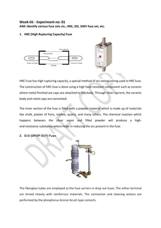
  • 1. Week-01 - Experiment no: 01 AIM: Identify various fuse sets viz., HRC, DO, 33KV fuse set, etc. 1. HRC (High Rupturing Capacity) Fuse HRC Fuse has high rupturing capacity, a special method of arc extinguishing used in HRC fuse. The construction of HRC fuse is done using a high heat-resistant component such as ceramic where metal finished are caps are attached to this body. Through silver-current, the ceramic body and metal caps are connected. The inner section of the fuse is filled with a powder material which is made up of materials like chalk, plaster of Paris, marble, quartz, and many others. The chemical reaction which happens between the silver vapor and filled powder will produce a high- end resistance substance where helps in reducing the arc present in the fuse. 2. D.O (DROP OUT) Fuse The fiberglass tubes are employed as the fuse carriers in drop out fuses. The either terminal are tinned heavily with nonferrous materials. The connection and cleaning actions are performed by the phosphorus bronze brush type contacts.
  • 2. The material used in drop out fuses should possess lower resistance as well as lower melting points, drop-out High voltage fuse (33KV) mounting plate is fixed in the middle of the support insulator. Support insulator has the upper and lower terminals for the connection wire. 3. Horn Gap Fuses Horn-Gap Fuse sets are of 11KV,22KV & 33KV voltage class, outdoor, vertically mounted are required for protection of transformers and tapping points. Rated current of Horn- Gap fuse sets shall be 50A/100A/200A/400A. Insulator of H.G Fuse shall be Porcelain (Pin/Post type)/ Solidcore /Polymeric type 4. Kit Kat Fuse Porcelain type kit kat Fuse Flush type kit kat Fuse Kit Kat Fuse is a semi-enclosed fuse also considered as rewireable fuse designed mainly for the domestic wiring and small-scale usage. 5. Automotive Fuse Automotive Fuse (Blade fuse type) used to protect the electrical components and devices of vehicle. They act as a safety measure to protect from overcurrent of an electrical circuit. Its basic purpose is to break the circuit when the current becomes more than the desired value, thereby preventing possible damage from equipment failures and short circuits.
  • 3. Week-01 - Experiment no: 02 (a) AIM: Measure and select the appropriate size of fuse wire. Standard fuse SWG table for the fuse elements used in this type are tinned copper wire, lead and tin alloy or aluminium wire.
  • 4. PROCEDURE: 1. Measure the gauge of given fuse wire/element using SWG. 2. Observer the Standard fuse SWG Table & Write down the Current rating in Observation Table. 3. Repeat the above procedure for the different fuse wire/elements. OBSERVATION TABLE: SL. No Fuse wire gauge in S.W.G Current rating as per the Standard table in Amps CONCLUSION:
  • 5. Week-01 - EXPERIMENT NO: 2(b) AIM: Test the HRC fuse by performing a Load test. APPARATUS REQUIRED: Sl. No Apparatus Range Quantity 1. HRC Fuse 2A 01 2. Voltmeter (A.C) 0-500V 01 3. Ammeter (A.C) 0-10A 01 4. S.P.S.T Switch ----------- 01 5. Lamp Load 0-2KW / 10 Amps 01 6. Patch Chords 1 Sq.mm As Required CIRCUIT DIAGRAM: OBSERVATION TABLE: Sl.No Load Current in Amps Current through HRC Fuse element in Amps Time of Operation in Seconds
  • 6. PROCEDURE: 1. Connections are made as per the circuit diagram. 2. Keep all the Load Switches in OFF position & Keep the SPST switch in Close Position. 3. Now Switch ON the Main supply, Observe the Voltmeter reading & confirm for rated voltage (1Ø- 230V). 4. Now switch ON the Loads in Stepwise, Observe the Load Current & Increase the load current up to more than 2 times of HRC Fuse current rating. 5. Now Open the SPST switch as well as start the STOP WATCH (Timmer). 6. Note down the Load current & HRC fuse Blows time. 7. Switch OFF the main Supply & Disconnect the circuit. CONCLUSION:
  • 7. Week- 02 - EXPERIMENT NO: 1(a) AIM: Identify the various types of CB- MCB, ELCB, RCCB, MPCB and MCCB. Trace and locate MCBs used in your institution and note down their specifications. I. Identify the various types of CB- MCB, ELCB, RCCB, MPCB and MCCB. MCB - Miniature Circuit Breakers. ELCB - Earth-leakage circuit breaker RCCB - Residual Current Circuit Breaker MPCB- Motor Protection Circuit Breaker MCCB - Moulded Case Circuit Breaker
  • 8. II. Trace and locate MCBs used in your institution and note down their specifications. MCB Place2: Place2: Place3: Specification Parameters Ranges Ranges Ranges Standard Conformity Standard Rated Current (In) Type of Curve Poles Rated Short Circuit Breaking Capacity (Icn) Rated Voltage (Ue) Rated Frequency(f) Rated Insulation Voltage (Ui) Ambient Temperature Contact indication mounting mode & mounting support
  • 9. Week- 02 - EXPERIMENT NO: 01(b) AIM: Dismantle MCCB or ELCB and identify various parts.
  • 10. Week- 02 - EXPERIMENT NO: 01(c) AIM: Test the MCB and plot its inverse time characteristic curve. APPARATUS REQUIRED: Sl.No Apparatus Range Quantity 1. M.C.B Fuse (Single Pole) 2A 01 2. Voltmeter (A.C) 0-500V 01 3. Ammeter (A.C) 0-10A 01 4. S.P.S.T Switch ----------- 01 5. Lamp Load 0-2KW / 10 Amps 01 6. Patch Chords 1 Sq.mm As Required CIRCUIT DIAGRAM: OBSERVATION TABLE: Sl.No Load Current in Amps Time of Operation in Seconds 1. 2. 3. 4. 5.
  • 11. PROCEDURE: 1. Connections are made as per the circuit diagram. 2. Keep all the Load Switches in OFF position & Keep the SPST switch in Close Position. 3. Now Switch ON the Main supply, Observe the Voltmeter reading & confirm for rated voltage (1Ø- 230V). 4. Now switch ON the Loads in Stepwise, Observe the Load Current & Increase the load current up to more than 2 times of MCB current rating. 5. Now Open the SPST switch as well as start the STOP WATCH (Timmer). 6. Note down the Load current & MCB Trip time. 7. Repeat the Steps No. 4, 5 & 6 for different load currents. 8. Switch OFF the main Supply & Disconnect the circuit. NATURE OF GRAPH: CONCLUSION:
  • 12. Week- 02 - EXPERIMENT NO: 02(a) AIM: Troubleshooting and servicing of LT circuit breaker. Troubleshooting of LT circuit breaker: Causes & Remedies 1. Identify Tripped Circuit Breaker Circuit breaker emits a humming sound when it is overloaded but has not switched off yet. Inside electric access panel, the tripped breaker lever can usually be found between the “on” and “off” position 2. Test Circuit Breaker Check the lever by moving it from ‘on’ to ‘off’ a couple of times to check how loose it is. If breaker has no ‘give’ and moves easily then it is faulty and you need to have it replaced as soon as possible. 3. Switch Off All of Appliances Again Switch off all appliances that are connected to circuit breaker but make sure to do it all at once to prevent a surge of electrical power when you reset it. If circuit breaker keeps on tripping then hire a professional to come and have a look at it. 4. Check Wiring If home has faulty wiring, then circuit breaker will be tripping continuously and you may find yourself receiving electrical shocks when powering certain appliances. This requires a trained professional so don’t try this on own. Simply identify the problem and hire a professional to take care of it. 5. Have Circuit Breaker Tested for the Necessary Voltage Touch one probe of the 120–240-volt tester to the tip of the “hot” wire, while touching the other tip to a bare copper grounding wire within the main electrical box. Use a neutral grounding terminal which is secured with ground wires and neutral wires for the probe. You will need to replace circuit breaker if you find the right amount of voltage present.
  • 13. Servicing steps of LT circuit breaker. 1. Evaluate, Clean, Service and Test 2. Insulating parts which include bushings should be wiped down and cleaned 3. Check fault operations. 4. Trip Testing to ensure manufacturer standards 5. Inspection of alignment conditions and stationary contacts 6. Remove damaged parts 7. Reset breaker operation mechanism to manufacturer’s instruction book 8. Primary and Secondary Testing 9. On Site Evaluation of breakers, bus ducts, and fuses
  • 14. Week- 02 - EXPERIMENT NO: 02(b) AIM: Test commercially available ACCL. APPARATUS REQUIRED: Sl.No Apparatus Range Quantity 1. A.C.C.L 32A 01 2. Voltmeter (A.C) 0-500V 01 5. Lamp Load 0-2KW / 10 Amps 01 6. Patch Chords 1 Sq.mm As Required CIRCUIT DIAGRAM: OBSERVATION TABLE: CURRENT LIMIT setting: _________Amps Sl. No E.B D.P switch D.G D.P switch Load Switch’s A.C.C.L Actions 1 ON OFF ON 2 OFF ON ON 3 ON ON ON 4 OFF ON TRIP
  • 15. PROCEDURE: 1. Connections are made as per the circuit diagram. 2. Keep all the Load Switches in OFF position. 3. Now Switch ON the Main supply, Switch ON the EB Side DP switch & observe the lamp Load by Switch ON the loads in Steps. 4. Now switch OFF the EB side DP switch & Switch ON the DG side DP. 5. Switch ON the Loads in Stepwise, Observe the Load Current & Increase the load current up to more than CURRENT LIMIT setting. 6. Observe the Results as per the Observation Table & write down the Actions by the ACCL. 7. Switch OFF the main Supply & Disconnect the circuit. CONCLUSION:
  • 16. Week-03 - EXPERIMENT NO: 1 AIM: Visit to Substation. a. Identify the parts of circuit breaker and check its operation. b. Demonstrate test tripping characteristic of circuit breaker for over current and short circuit current. Parts of Circuit Breaker
  • 17. Week-03 - EXPERIMENT NO: 2 AIM: a. Demonstrate Installation operation and maintenance of SF6 circuit breaker, Vacuum circuit breaker. b. Carry out timer test on circuit breakers. c. Demo on RMU
  • 18. Week-04 - EXPERIMENT NO: 1 AIM: a. Demonstrate various parts of the relay and ascertain the operation. b. Demonstrate setting of pick-up current/ time setting multiplier for relay operation Pick Up Current of Relay: In all electrical relays, the moving contacts are not free to move. All the contacts remain in their respective normal position by some force applied to them continuously. This force is called the controlling force of the relay. This controlling force may be the gravitational force, may be a spring force, or may be a magnetic force. The force applied to the relay’s moving parts for changing the normal position of the contacts is called deflecting force. This deflecting force is always in opposition of controlling force and is present always in the relay. The current for which the relay initiates its operation is called pick up current of relay. Current Setting of Relay: The minimum pick up value of the deflecting force of an electrical relay is constant. Again, the deflecting force of the coil is proportional to its number of turns and current flowing through the coil. Now, if we can change the number of active turns of any coil, the required current to reach at minimum pick value of the deflecting force, in the coil also changes. The current setting of relay is expressed in percentage ratio of relay pick up current to rated secondary current of CT.
  • 19. Plug Setting Multiplier of Relay: Plug setting multiplier of relay is referred as ratio of fault current in the relay to its pick up current. Suppose we have connected on protection CT of ratio 200/1 A and current setting is 150%. Hence, pick up current of the relay is, 1 × 150 % = 1.5 A Now, suppose fault current in the CT primary is 1000 A. Hence, fault current in the CT secondary, i.e., in the relay coil is, 1000 × 1/200 = 5A Therefore PSM of the relay is, 5 / 1.5 =3.33 Time Setting Multiplier of Relay: The operating time of an electrical relay mainly depends upon two factors : • How long distance to be travelled by the moving parts of the relay for closing relay contacts and • How fast the moving parts of the relay cover this distance. So far by adjusting relay operating time, both of the factors to be adjusted. The adjustment of traveling distance of an electromechanical relay is commonly known as time setting. This adjustment is commonly known as time setting multiplier of relay. The time setting dial is calibrated from 0 to 1 in steps of 0.05 sec. Hence, actual operating time of the relay is 3 × 0.1 = 0.3 sec. i.e. 10% of 3 sec.
  • 20. Week-04 - EXPERIMENT NO: 2(a) AIM: Test the Earth Leakage Relay. APPARATUS REQUIRED: Sl.No Apparatus Range Quantity 1. Earth Leakage Relay kit Digital type 01 2. C.B.C.T with Lamp load --- 01 3. Patch Chords 1 Sq.mm As Required CIRCUIT DIAGRAM:
  • 21. OBSERVATION TABLE: Leakage Current Setting: _________Amps Sl. No Lamp load Circuit Conditions Leakage Current In Amps Trip Circuit 1 Normal 2 Earth Leakage fault PROCEDURE: 1. Connections are made as per the circuit diagram. 2. Keep all the Load Switches in OFF position. 3. Now Switch ON the Main supply, Switch ON the lamps under normal condition. 4. Now switch OFF Lamp load, main supply & alter the circuit as the current leakage to earth. 5. Switch ON the main supply, Lamp load & Observe the Load leakage current & Trip condition. 6. Observe the Results & Note down in the Observation table. 7. Switch OFF the main Supply & Disconnect the circuit CONCLUSION:
  • 22. Week-04 - EXPERIMENT NO: 2(b) AIM: Test the Electromechanical over voltage relay. APPARATUS REQUIRED: Sl.No Apparatus Range Quantity 1. Electromechanical over voltage relay kit Electromechanical type 01 2. Patch Chords 1 Sq.mm As Required CIRCUIT DIAGRAM:
  • 23. OBSERVATION TABLE: Plug Setting (PS) : _________ Volts, Sl. No Plug Setting Multiplier (PSM) Applied Voltage = PS × PSM in Volts TSM: TSM: Operating Time in Seconds Operating Time in Seconds 1 2 3 4 5 6 PROCEDURE: 1. Connections are made as per the circuit diagram. 2. Make the Settings of PS as per the decide value & keep all the Load Switches in OFF position. 3. Now Switch ON the Main supply & Apply the Calculated Applied voltage. 4. Now reset the relay, if it is operated then Confirm the Disc Halt on Position. 5. Switch to Set Position, Observe Timmer & Trip condition. 6. Note down the Operating Time in the Observation table. 7. Repeat the Steps 4 , 5 & 6 for different PMS, Applied Voltage & TSM. 8. Switch OFF the main Supply & Disconnect the circuit NATURE GRAPH: CONCLUSION:
  • 24. Week-05 - EXPERIMENT NO: 1 AIM: Test the Static Over Voltage and Under Voltage Relay and Plot its inverse time – Voltage Characteristics. APPARATUS REQUIRED: Sl.No Apparatus Range Quantity 1. Static / Microprocessor Over Voltage and Under Voltage Relay kit Microprocessor type 01 2. Patch Chords 1 Sq.mm As Required CIRCUIT DIAGRAM:
  • 25. OBSERVATION TABLE: For Over Voltage (OV) % age of over Voltage = _______ % Pick up Voltage (Vs) = 1 + (0.05 + Σ a) Vn Volts = ________________________ Volts, Where Vn=110V Voltage Set switch Value (Σa) = Sl. No Applied Voltage in Volts Operating Time in Seconds 1 2 3 4 5 For Under Voltage (UV) % age of over Voltage = _______ % Pick up Voltage (Vs) = 1 - (0.05 + Σa) Vn Volts = ________________________ Volts, Where Vn=110V Voltage Set switch Value (Σa) = Sl. No Applied Voltage in Volts Operating Time in Seconds 1 2 3 4 5
  • 26. PROCEDURE: 1. Connections are made as per the circuit diagram. 2. Make the Switch Settings as per Requirement like OV/UV. 3. Decide the %age of OV/UV, accordingly calculate the Vs. 4. Now make the Switch Settings of Vs as per the Value of Σa. 5. Switch ON the Main supply & apply the different voltages (OV/UV). 6. Observe the Timmer, Trip condition, note down the Operating Time & Voltage in the Observation table. 7. Reset the relay & repeat the step No. 6 for different Voltages (UV/OV). 8. Switch OFF the main Supply & Disconnect the circuit. NATURE GRAPH: CONCLUSION:
  • 27. Week-05 - EXPERIMENT NO: 2(a) AIM: Program and test the Numerical Over Current for definite Time operations. APPARATUS REQUIRED: Sl.No Apparatus Range Quantity 1. Numerical / Digital Over Current Relay Kit Digital Over Current type 01 2. Patch Chords 1 Sq.mm As Required CIRCUIT DIAGRAM: OBSERVATION TABLE: Sl. No Set Current in Amps Set definite Time in Seconds Operating Current in Amps Operating Time in Seconds 1 2 3
  • 28. PROCEDURE: 1. Connections are made as per the circuit diagram. 2. Switch ON the Main supply. 3. Set the Current & Time as per the operation procedure of relay. 4. Switch OFF & Switch ON the Main supply then apply the Current more than the Set Value using current source. 5. Now Switch to Starts operation & Observe the Timmer, Trip condition, note down the Operating Time & Current in the Observation table. 6. Set the relay for different Current & Time. 7. Repeat the steps No. 4 & 5. 8. Switch OFF the main Supply & Disconnect the circuit. NATURE GRAPH: CONCLUSION:
  • 29. Week-06 - EXPERIMENT NO: 01 AIM: Test the operation of Buchholz Relay. APPARATUS REQUIRED: Sl.No Apparatus Range Quantity 1. Buchholz Relay Kit -- 01 2. Transformer oil -- 5 Litters 3. Patch Chords 1 Sq.mm As Required EXPERIMENTAL DIAGRAM:
  • 30. OBSERVATION TABLE: Sl. No Air Pump Trip Circuit 1 OFF 2 ON PROCEDURE: 1. Make sure the transformer tank and relay are filled with oil and there is some oil in conservator tank, the air valve of the Buchholz relay must be closed. 2. Now turn ON the air Pump and the air bubbles starts blowing into the Buchholz relay. The Air Pump is fitted with a non-return valve to protect the compressor by reverse flow of oil. 3. Notice the relays trips after some time of air flow & simultaneously to the air pump is cut OFF. 4. Turn OFF the Air Pump switch and then release the air valve on the Buchholz relay. CONCLUSION:
  • 31. Week - 06 - EXPERIMENT NO: 02 AIM: Conduct BDVT on Transformer oil. Sl.No Apparatus Range Quantity 1. BDVT on Transformer oil Kit 0-60KV / 1KVA 01 2. Transformer oil -- 1 Litters 3. Patch Chords 1 Sq.mm As Required EXPERIMENTAL DIAGRAM: OBSERVATION TABLE: Sl. No Distance of Electrodes in mm Breakdown Voltage in KV 1 2.5 2 4 3
  • 32. PROCEDURE: 1. Adjust the gap between electrodes to 2.5mm/4mm by the guage. 2. Fill the cup with oil and place it on the H.T electrodes. Close the hood properly, so as to operate the interlock microswitch which acts as a safety precaution for the operator. 3. Switch ON the main supply, the corresponding lamp will glow. 4. Press the H.T ON push Button the contactor will operate and H.T ON lamp will glow. If the contactor does not operate, it means that the Variac brush arm is not at zero position OR the Hood interlock microswitch is not closed as mentioned in ‘step 2’. The zero interlocking od the variac is another safety feature against switching on the unit directly at a higher voltage. This will be indicated by the Voltmeter reading also. 5. Raise the voltage by turning the variac knob in clockwise direction. In case the oil sample fails the unit will trip to lower down the voltage turn the variac knob anti-clock and bring it to zero position before start of further tests. CONCLUSION: