Downloaded 403 times
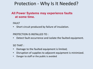
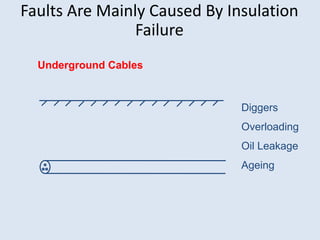
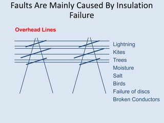
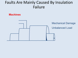
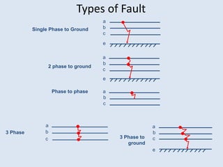
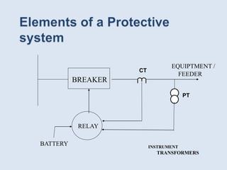
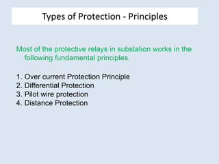


The document provides an overview of substation protection basics. It discusses why protection is needed to detect faults and isolate faulty equipment. The main types of faults are described along with the causes of insulation failures. The types of protection principles covered include overcurrent, differential, pilot wire, and distance protection. Key elements of a protection scheme like circuit breakers, relays, batteries, and transformers are also mentioned.


![protection of transmission lines[distance relay protection scheme]](https://cdn.slidesharecdn.com/ss_thumbnails/os-exe3-23-may2011-sr-i-776s21tr-lineprotection-120425095503-phpapp02-thumbnail.jpg?width=640&height=640&fit=bounds)


