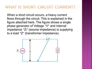
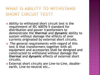
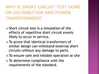
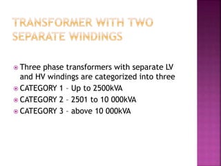
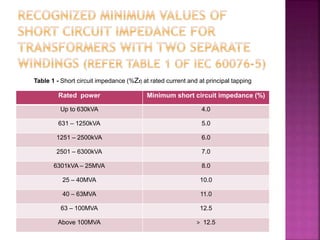
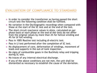
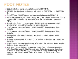
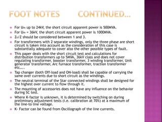
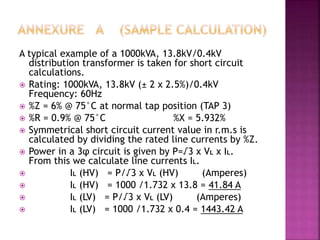
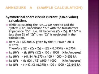
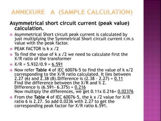
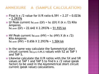
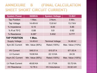
SlideShare a Scribd company logo
Presented by
S.M.G. MUTHAR HUSSAIN
Transformer Engineer
 WHAT IS SHORT CIRCUIT?
 WHAT IS SHORT CIRCUIT CURRENT?
 WHAT IS THE DIFFERENCE BETWEEN SHORT CIRCUIT
AND OVERLOAD?
 WHAT CAUSES A SHORT CIRCUIT?
 WHAT IS THE EFFECT OF SHORT CIRCUIT?
 WHAT IS ABILITY TO WITHSTAND SHORT CIRCUIT TEST?
 WHY IS SHORT CIRCUIT TEST DONE ON DISTRIBUTION.
AND POWER TRANSFORMERS?
 TRANSFORMER WITH TWO SEPARATE WINDINGS
 RECOGNIZED MINIMUM VALUES OF SHORT CIRCUIT
IMPEDANCE
 SHORT CIRCUIT APPARENT POWER OF THE SYSTEM
 WHAT IS SYMMETRICAL SHORT CIRCUIT CURRENT?
 SYMMETRICAL SHORT CIRCUIT CALCULATIONS
 WHAT IS ASYMMETRICAL SHORT CIRCUIT CURRENT?
 ASYMMETRICAL SHORT CIRCUIT CALCULATIONS
 SC TEST PROCEDURES FOR TRANSFORMERS WITH 2
WINDINGS
 SC TEST SETUP IN HI-POWER LAB
 DETECTION OF FAULTS
 EVALUATION OF COMPLIANCE TO STANDARD
 FOOT NOTES
 REFERENCES
 ANNEXURE A (Sample Calculation)
 ANNEXURE B (Final Calculation Sheet)
 Whenever a fault occurs on a network such
that a large current flows in one or more
phases, a short circuit is said to have
occurred.
When a short circuit occurs, a heavy current
flows through the circuit. This is explained in the
figure attached here. The figure shows a single
phase generator of Voltage “V” and internal
impedance “Zi” (source impedance) is supplying
to a load “Z” (transformer impedance).
•Under normal load conditions, the current in
the circuit is limited by load impedance “Z”.
•However if the load terminals get shorted
due to some reason, the circuit impedance
is reduced to a very low value being “Zi” in
this case. As “Zi” is very small, therefore a
large current flows through the circuit. This
is called the short circuit current.
 People usually get confused with over load and short
circuit as both of them cause trouble to the system in
similar way. It is worthwhile to make a distinction
between a short circuit and an overload. When a
“short circuit” occurs, the voltage at fault point is
reduced to Zero and current of abnormally high
magnitude flows through the network to the point of
fault.
 On the other hand, an “overload” means that load
loads greater than the designated values have been
imposed on the system. Under such condition the
voltage at the overload point may be low, but not
Zero. The under voltage condition may extend for
some distance beyond the over load point into the
remainder of the balance. The currents in the
overloaded equipment are high but are substantially
lower than that in the case of a short circuit.
 A short circuit in the power system is the result of
some kind of abnormal conditions in the system. It
may be caused due to “internal” and or “external”
effects.
 Internal effects are caused by breakdown of
equipment or transmission lines from deterioration of
insulation in a generator, transformer etc… such
troubles may be due to ageing of insulation,
inadequate design or improper installation.
 External effects causing short circuit include
insulation failure due to lightning surges, contact of
live wires due to high speed winds, earth quakes,
falling of a tree, bird or snake shorting, overloading
of equipment causing excessive heating, mechanical
damage by public etc…
 In case of a short circuit, the current in the system
increases to an abnormally high value while the
system voltage decreases to a low value.
 The heavy current due to short circuit causes
excessive heating which may result in fire or
explosion. Sometimes short circuit takes the form of
an arc and causes considerable damage to the
system. For example an arc on a transmission line not
cleared quickly will burn the conductor severely
causing it to break, resulting in a long time
interruption of line.
 The low voltage created by the fault has a very
harmful effect on the service rendered by the power
system. If the voltage remains low for even a few
seconds, the consumer’s motors may be shut down
and generators on the power system may become
unstable.
 Due to the above effects of short circuit it is
desirable and necessary to disconnect the faulty
section and restore normal voltage and current
conditions as quickly as possible. Short circuit can
produce very high temperatures due to the high
power dissipation in the circuit. This high
temperature can be utilized in the application.
 “Arc welding” is a common example of the practical
application of the heating due to a short circuit. The
power supply for an arc welder can supply very high
currents that flow through the welding rod and the
metal pieces being welded. The point of contact
between the rod and the metal surfaces gets heated
to the melting point, fusing a part of the rod and
both surfaces into a single piece.
 Ability to withstand short circuit test is the
requirement of IEC 60076-5 standard for
distribution and power transformers to
demonstrate the thermal and dynamic ability to
sustain without damage the effects of over
currents originated by external short circuits.
 The general requirements with regard of this
test is that transformers together with all
equipment and accessories shall be designed and
constructed to withstand without damage the
thermal and dynamic effects of external short
circuits.
 External short circuits are Line-to-Line, double-
earth, Line-to-neutral etc…
 Short circuit test is a simulation of the
effects of repetitive short circuit events
likely to occur in service.
 To prove that identical transformers of
similar design can withstand external short
circuits without any damage to parts.
 To ensure safe and reliable operation at site
 To determine compliance with the
requirements of the standard.
 Three phase transformers with separate LV
and HV windings are categorized into three
 CATEGORY 1 – Up to 2500kVA
 CATEGORY 2 – 2501 to 10 000kVA
 CATEGORY 3 – above 10 000kVA
Rated power Minimum short circuit impedance (%)
Up to 630kVA 4.0
631 – 1250kVA 5.0
1251 – 2500kVA 6.0
2501 – 6300kVA 7.0
6301kVA – 25MVA 8.0
25 – 40MVA 10.0
40 – 63MVA 11.0
63 – 100MVA 12.5
Above 100MVA > 12.5
Table 1 - Short circuit impedance (%Zt) at rated current and at principal tapping
Highest voltage for equipment, Um (kV) Short circuit apparent power (MVA)
7.2, 12, 17.5, 24 500
36 1000
52 and 72.5 3000
100 and 123 6000
145 and 170 10000
245 20000
300 30000
362 35000
420 40000
525 60000
765 83500
The short circuit apparent power in MVA of the system at the
test lab should be specified to calculate the value of the
Symmetrical short circuit current to be used during SC testing.
If the short circuit apparent power of the system is not
specified, the values are taken from Table 2 of IEC 60076-5.
Table 2 - Short circuit apparent power of the system
 A fault current with No DC offset is a
symmetrical short circuit current.
The symmetrical short circuit current in the
three phases is displaced equally by 120° due
to the symmetry that exists when all the
three phases are shorted. It is the most
severe type of fault involving largest r.m.s
current, but it occurs rarely. For this reason
balanced short- circuit calculation is
performed to determine these large
currents.
 Symmetrical short circuit current (r.m.s value) is calculated using
the measured short circuit impedance “Zt” of the transformer
and the System impedance “Zs”.
For transformers falling under CATEGORY 1, the System
impedance “Zs” is neglected if is equal to or less than 5% of the
transformer impedance “Zt”.
 To be more precise, Symmetrical short circuit current value in
r.m.s is got by simply dividing the rated line current by %Z.
 We know the Power in a three phase circuit is P=√3 x VL x IL
 From this we can calculate line current IL
 IL (HV) = P/√3 x VL (HV) (Amperes)
 IL (LV) = P/√3 x VL (LV) (Amperes)
 The Symmetrical short circuit current is then calculated as follows
 ISC (HV) = (IL (HV) /%Z) x 100 / 1000 (Kilo Amperes)
 ISC (LV) = (IL (LV) /%Z) x 100 / 1000 (Kilo Amperes)
 NOTE: While calculating the ISC (Sym), we need to add the System
(Lab) impedance “Zs” with the transformer impedance “Zt”. i.e.
%Z becomes (Zt + Zs). If “Zs” is less than 5% of “Zt” then “Zs” is
neglected in the calculation.
 A fault current with DC offset is an Asymmetrical
short circuit current. Asymmetrical Short circuit
involves only one or two phases. Hence there exists
asymmetry and the three phases become unbalanced.
 Asymmetrical short circuit often occurs between line-
to-ground or between lines. In single line-to-ground
fault, one conductor comes in contact with the
ground or the neutral conductor. A line-to-line fault
occurs when two conductors are short circuited
 During the first half of a cycle, the fault current is at
its largest magnitude occurring at a moment when
the voltage wave is passing the reference axis i.e.
Zero. This asymmetry is brought on by the DC offset
current. At the half cycle mark, the peak value of the
asymmetrical current is about ~1.6 times the
symmetrical current.
X/R 1 1.5 2 3 4 5 6 8 10 14
k x √2 1.51 1.64 1.76 1.95 2.09 2.19 2.27 2.38 2.46 2.55
Asymmetrical Short circuit PEAK current is calculated by just multiplying
the Symmetrical Short circuit current r.m.s value with the PEAK FACTOR.
Peak factor is k x √2
To find the value of k x √2 we need to calculate first the X/R ratio of the
transformer and refer Table 4 of IEC 60076-5.
LV Peak current ISC-peak (LV) = ISC (LV) X (k x √2) Kilo Amperes
HV Peak current ISC-peak (HV) = ISC (HV) X (k x √2) Kilo Amperes
Table 4 – Values for k x √2
If not otherwise specified, in case X/R >14 the factor k x √2 is
assumed equal to 1.88 x √2 = 2.55 for transformers of CATEGORY 2
1.9 x √2 = 2.69 for transformers of CATEGORY 3
 S.C. test is carried on a new transformer with the protection accessories
like the Buchholz relay and Pressure relief device mounted on it.
 Before the S.C. test, the transformer shall be subjected to Routine tests
as per IEC-60076-1 and the test results made available.
 LI test is not required at the start and is performed after the completion
of SC test as a verification test.
 Measure the Resistance and Reactance of the winding with tapping (i.e.
HV winding) at Tap 1, Tap 3 and Tap 5 at which SC test will be carried
out.
 The temperature of the windings shall be between 10 to 40°C before the
start of SC test.
 During the tests, winding temperature may increase due to the
circulation of the short circuit current.
 For thermal ability to withstand short circuit only symmetrical short
circuit current Isc (sym) is applied. The test duration is 2s.
 Tolerance on the symmetrical r.m.s value of the short circuit test current
is 10% from the specified value.
 The maximum permissible value of the average temperature of each
winding after short circuit is 250°C for Copper and 200°C for Aluminum
for Class A insulation.
 For three phase transformers, a three phase supply is used.
 The winding closer to the core is to be short circuited in order to avoid
saturation of the magnetic core which could lead to an excessive
magnetizing current superimposed on the short circuit current during the
first few cycles.
 For dynamic ability to withstand short circuit Asymmetrical short circuit
current Isc (asym) is applied. The test duration is 0.5s for Category 1 and
0.25s for Category 2 with a tolerance of ±10%
 Tolerance on the Asymmetrical peak value of the short circuit test
current is 5% from the specified value
 To obtain the initial peak value of the Asymmetrical current in the phase
winding under test, the moment of switching ON shall be adjusted by
means of a synchronous switch.
 The values of Isc (asym) and Isc (sym) are checked using the Oscilloscope and
Oscillographic recordings are made.
 In order to obtain the maximum asymmetry of the current in one of the
phase windings, the switching ON must occur at the moment the voltage
applied to this winding passes through Zero.
 The frequency of the test supply shall be the same as the rated
frequency of the transformer and the voltage of the test supply is
suitably adjusted with respect to the rated voltage of the transformer.
 Hence LV windings which are close to the core are shorted through shunt
resistance
 For three phase transformers, a three phase supply is used.
 The winding closer to the core is to be short circuited in order to avoid
saturation of the magnetic core which could lead to an excessive
magnetizing current superimposed on the short circuit current during the
first few cycles.
 Hence LV windings which are close to the core are shorted through shunt
resistance
 Short circuit current is applied from the HV side in each phase by
adjusting the supply voltage such that rated LV Short circuit current flows
through it.
 Preliminary adjustment test (calibration at 70% of the specified current)
is done to check the proper functioning of the test setup with regard to
the moment of switch ON, the current setting, the damping and the
duration.
 For categories 1 and 2 three phase transformers, the total number of
tests shall be nine. I.e. three tests on each phase.
 The nine tests on a three phase transformer with tapping are made in
different tap positions i.e., three tests in the position corresponding to
the highest voltage ratio on one of the outer phases, three tests on the
principal tapping on the middle phase and three tests in the position
corresponding to the lowest voltage ration on the other outer phase.
 Test Sequence simplified:
 Following sequence of short circuit current
applications is specified for three phase
transformers classified under Category 1 and
2 as per IEC 60076-5
 3 shorts in φU at TAP 1
 3 shorts in φV at TAP 3
 3 shorts in φW at TAP 5
Short circuit testing laboratories are required in order to test the transformers at
different short circuit currents. The short circuit testing set up is given in Fig
11.15.
It consists of a short circuit testing generator in association with a master circuit
breaker, reactor and measuring devices. A make switch initiates the short circuit
and the master circuit breaker isolates the test device from the source at the end
of a pre-determined time set on a test sequence controller. Also the master circuit
breaker can be tripped if the test device fails to operate properly. Short circuit
generators with induction motors as prime movers are also available.
 Any difference between the results of measurements
made before and after the test may be used as a
criterion for determining possible defects.
 The Oscillographic recordings of applied voltage,
currents at 70% and 100% and combustible gasses
collected in the Buchholz relay all serves as
reference for detection of faults. Further the visual
inspection of the tank from outside helps detection
of faults.
 The variation in reactance measured (2% for helical
winding and 4% for foil winding) before and after SC
test forms the basis for detection of faults.
 The Active part shall be removed from the tank for
inspection of core and windings. The possible
defects, possible cause and verification test are
summarized as below.
Defect Possible Cause Check
Change in Oscillographic
recordings of applied voltages
and currents
Displacement of windings from
position resulting asymmetry
SFRA test
Increase in Short circuit
reactance Bulging of coils
All the reactance measurements
made per phase shall be to a
repeatability of better than ±0.2%
Noise and Vibration Loose core and clamping, loose
assembly
Noise level test
Abnormal current between tank
and earth
Grounded core / Shorted core No load loss test and excitation
current measurement
Tank Bulging Excess pressure developed
during gas formation and burning
of windings
Pressure deflection test
Combustible gas collected in
Buchholz relay and tripping
Gasses formed due to burning of
insulation and oil
DGA test
Change in magnetizing current Core disturbed SFRA test
Inter turn to turn fault Weak /damaged turn to turn
insulation, loose winding and gap
between turns
Measure short circuit reactance
from HV as well as LV side
Movement / Shifting of leads and
position
Leads not held properly during
manufacturing / improper /
inadequate support and
tightening
LI test
 In order to consider the transformer as having passed the short
circuit test the following condition shall be fulfilled.
 No variation in the Oscillographic recordings when compared with
those at the start of the SC test and at the end of the test.
 The short circuit reactance values in ohms, calculated on per
phase basis or each phase at the end of the tests do not differ
from the original values by more than 2% for helical winding and
4% for LV foil winding.
 Pass in 100% Routine test including di-electric test.
 Pass in LI test performed after the completion of SC test.
 No displacement of core, deformation of windings, movement of
leads and supports in the out-of-tank inspection.
 No signs of combustible gases in the Buchholz relay and tripping
during SC test.
 No traces of any internal electrical discharge.
 If any of the above conditions are not met, the unit shall be
dismantled as necessary to establish the cause of the deviation.
 SEC distribution transformers fall under CATEGORY 1.
 PRIVATE distribution transformers fall either in CATEGORY 1 or CATEGORY
2.
 Both SEC and PRIVATE power transformers fall under CATEGORY 3.
 For transformers falling under CATEGORY 1, the System impedance “Zs” is
neglected if is equal to or less than 5% of the transformer impedance
“Zt”.
 Thumb rule: Short circuit current = Rated current x how many times
greater short circuit the transformer can withstand.
 Z=4% means, the transformer can withstand 25 times greater short
circuits.
 Z=5% means, the transformer can withstand 20 times greater short
circuits.
 Z=6% means, the transformer can withstand 17 times greater short
circuits.
 The currents resulting from a short circuit in the windings are called over
currents.
 In a three 1φ transformers forming a 3φ bank, the value of power applies
to three phase bank rating.
 The Short circuit apparent power and ratio of Z0/Z of the system (test
lab) should be specified by the purchaser during the enquiry stage itself
in order to calculate the Isc(sym) to be used in design and testing. If not
specified the values can be taken from Table 2 of IEC-60076-5: 2000
edition.
 For Um up to 24kV, the short circuit apparent power is 500MVA.
 For Um = 36kV, the short circuit apparent power is 1000MVA.
 Z0/Z should be considered between 1 and 3.
 For transformers with 2 separate windings, only the three phase are short
circuit is taken into account as the consideration of this case is
substantially adequate to cover also the other possible types of fault.
 This paper deals with the short circuit test and calculations for
distribution transformers up to 5MVA, 36kV class and does not cover
regulating transformer, booster transformer, 3 winding transformer, Unit
generator transformer, Arc furnace transformer, traction transformer
etc…..
 Tap changer (both Off-load and ON-load) shall be capable of carrying the
same over currents due to short circuit as the windings.
 The neutral terminal of the Star connected windings shall be designed for
the highest over current to flow through it.
 The mounting of accessories does not have any influence on the behavior
during SC test.
 Where K-factor is unknown, it is determined by switching on during
preliminary adjustment tests (i.e. calibration at 70%) at a maximum of
the line-to line voltage.
 K- Factor can be found from Oscillograph of the line currents.
 International Standard IEC 60076-5 Second
edition 2000-07
 Fundamentals of High Voltage Engineering
by Abdulrhman Al-Arainy, Mohammad Iqbal
Qureshi, Nazar Malik
A typical example of a 1000kVA, 13.8kV/0.4kV
distribution transformer is taken for short circuit
calculations.
 Rating: 1000kVA, 13.8kV (± 2 x 2.5%)/0.4kV
Frequency: 60Hz
 %Z = 6% @ 75°C at normal tap position (TAP 3)
 %R = 0.9% @ 75°C %X = 5.932%
 Symmetrical short circuit current value in r.m.s is
calculated by dividing the rated line currents by %Z.
 Power in a 3φ circuit is given by P=√3 x VL x IL.
From this we calculate line currents IL.
 IL (HV) = P/√3 x VL (HV) (Amperes)
 IL (HV) = 1000 /1.732 x 13.8 = 41.84 A
 IL (LV) = P/√3 x VL (LV) (Amperes)
 IL (LV) = 1000 /1.732 x 0.4 = 1443.42 A
Symmetrical short circuit current (r.m.s value)
calculation.
 While calculating the ISC(Sym), we need to add the
System (Lab) impedance “Zs” with the transformer
impedance “Zt”. i.e. %Z becomes (Zt + Zs). If “Zs” is
less than 5% of “Zt” then “Zs” is neglected in the
calculation.
 Here Zt = 6% and Zs given by the Hi-Power lab is
0.375%.
Therefore %Z = (Zt + Zs) = (6% + 0.375%) = 6.375%
 ISC (HV) = (IL (HV) /%Z) x 100 / 1000 (Kilo Amperes)
 ISC (HV) = (41.84 /6.375) x 100 / 1000 = 0.656 kA
 ISC (LV) = (IL (LV) /%Z) x100 / 1000 (Kilo Amperes)
 ISC (LV) = (1443.42 /6.375) x 100 / 1000 = 22.642 kA
Asymmetrical short circuit current (peak value)
calculation.
 Asymmetrical Short circuit peak current is calculated by
just multiplying the Symmetrical Short circuit current r.m.s
value with the peak factor.
 PEAK FACTOR is k x √2
 To find the value of k x √2 we need to calculate first the
X/R ratio of the transformer
 X/R = 5.932/0.9 = 6.591
 Now refer Table 4 of IEC 60076-5 to find the value of k x√2
corresponding to the X/R ratio calculated. It lies between
2.27 (6) and 2.38 (8).Difference is (2.38 – 2.27) = 0.11
Find the difference between the X/R and % Z.
Difference is (6.591- 6.375) = 0.216
Now multiply the differences, we get 0.11x 0.216= 0.02376
 From the Table 4 of IEC 60076-5, the k x √2 value for X/R
ratio 6 is 2.27. So add 0.0236 with 2.27 to get the
corresponding peak factor for X/R ratio 6.591.
 Final k x √2 value for X/R ratio 6.591 = 2.27 + 0.0236
= 2.29376
 LV Peak current ISC-peak (LV) = ISC (LV) X (k x √2) Kilo
Amperes
ISC-peak (LV) = 22.642 X 2.29376 = 51.935 kA
 HV Peak current ISC-peak (HV) = ISC (HV) X (k x √2)
Kilo Amperes
ISC-peak (HV) = 0.656 X 2.29376 = 1.504 kA
 In the same way calculate the Symmetrical short
circuit current ISC(sym) r.m.s values with %Z at TAP 1
and TAP 5.
 Likewise calculate the X/R ratios with the %X and %R
values at TAP 1 and TAP 5 to find k x √2 value (peak
factor) to be used in the Asymmetrical short circuit
current (peak value) calculations.
System Power 500MVA System Voltage 13.8kV
Tap Position 1 Max. 3 Nom. 5 Min.
Tap Voltage 14.49 kV 13.8 kV 13.11kV
% Impedance 6.15 6.00 5.85
% R at 75°C 0.88 0.9 0.92
% Reactance 6.087 5.932 5.777
TAP POSITION 1 Max.
Supply Voltage 14.49 kV Terminal Voltage 14.49 kV
Sym.SC Current Min. Value (90%) Rated (100%) Max. Value (110%)
HV Current 549.51 A 610.57 A 671.63 A
LV Current 19.90 KA 22.12 KA 24.33
Asym.SC Current Min. Value (95%) Rated (100%) Max. Value (105%)
LV Peak Current 48.60 KA 51.17 KA 53.72 KA
HV Reactance 12.78 Ω HV Inductance 33.92 mH
TAP POSITION 3 Nom.
Supply Voltage 13.8 kV Terminal Voltage 13.8 kV
Sym.SC Current Min. Value (90%) Rated (100%) Max. Value (110%)
HV Current 590.67 A 656.31 A 721.94 A
LV Current 20.38 kA 22.64 kA 24.91 kA
Asym.SC Current Min. Value (95%) Rated (100%) Max. Value (105%)
LV Peak Current 49.33 kA 51.94 kA 54.53 kA
HV Reactance 11.30 Ω HV Inductance 29.98 mH
TAP POSITION 5 Min.
Supply Voltage 13.11 kV Terminal Voltage 13.11 kV
Sym.SC Current Min. Value (90%) Rated (100%) Max. Value (110%)
HV Current 636.72 A 707.46 A 778.21 A
LV Current 20.87 KA 23.19 KA 25.50 KA
Asym.SC Current Min. Value (95%) Rated (100%) Max. Value (105%)
LV Peak Current 50.14 KA 52.78 KA 55.42 KA
HV Reactance 9.93 Ω HV Inductance 26.35 mH
 We know the %Z is expressed in Ohms per phase as
 Z (Ω) = %Z x (VL )² / 100 x MVA
 Example: %Z of a 1000kVA (1MVA) transformer at Tap
3 and @75°C = 6%
 Therefore Z (Ω) = 6 x (13.8)² / 100 x1 = 11.43Ω
 Similarly %X is expressed in Ohms per phase as
 X (Ω) = %X x (VL )² / 100 x MVA
 Example: %X of a 1000kVA (1MVA) transformer at Tap
3 = 5.932%
 Therefore X (Ω) = 5.932 x (13.8)² / 100 x1 = 11.30Ω
 Likewise %R is also expressed in Ohms per phase as
 R (Ω) = %R x (VL )² / 100 x MVA
 Example: %R of a 1000kVA (1MVA) transformer at Tap
3 and @75°C = 0.9%
 Therefore R (Ω) = 0.9 x (13.8)² / 100 x1 = 1.71Ω
 We know that the Inductive reactance XL is
given by XL = ω L
 Where “L” is the inductance “ω” is 2πf in a
resonance circuit and “f” is the resonance
frequency (60Hz).
 Therefore XL = 2πf L
 And L = XL / 2πf = 11.30/2x3.14x60 =
29.98mH
END OF PAPER

More Related Content

What's hot

Electrical grounding and earthing systems
Electrical grounding and earthing systemsElectrical grounding and earthing systems
Electrical grounding and earthing systems
Biswajit Pratihari
 
Transformer testing
Transformer testingTransformer testing
Transformer testing
ajayknows
 

What's hot (20)

Transformers protection, an introduction
Transformers protection, an introductionTransformers protection, an introduction
Transformers protection, an introduction
 
Testing of transformer
Testing of transformerTesting of transformer
Testing of transformer
 
Transformer protection
Transformer protectionTransformer protection
Transformer protection
 
Electrical grounding and earthing systems
Electrical grounding and earthing systemsElectrical grounding and earthing systems
Electrical grounding and earthing systems
 
Basics of busbar protection
Basics of busbar protectionBasics of busbar protection
Basics of busbar protection
 
Switchgear
SwitchgearSwitchgear
Switchgear
 
Transformer testing
Transformer testingTransformer testing
Transformer testing
 
Protection and Switchgear
Protection and SwitchgearProtection and Switchgear
Protection and Switchgear
 
Substation design-guideliness
Substation design-guidelinessSubstation design-guideliness
Substation design-guideliness
 
Transformers Protection
Transformers ProtectionTransformers Protection
Transformers Protection
 
Power system protection topic 1
Power system protection topic 1Power system protection topic 1
Power system protection topic 1
 
Transformer protection
Transformer protectionTransformer protection
Transformer protection
 
Dc Power System
Dc Power SystemDc Power System
Dc Power System
 
Resistance potential divider
Resistance potential dividerResistance potential divider
Resistance potential divider
 
Single line diagram
Single line diagramSingle line diagram
Single line diagram
 
High voltage underground cables
High voltage underground cablesHigh voltage underground cables
High voltage underground cables
 
Substation overview
Substation overviewSubstation overview
Substation overview
 
Safe Operation and Maintenance of Circuit Breakers and Switchgear
Safe Operation and Maintenance of Circuit Breakers and SwitchgearSafe Operation and Maintenance of Circuit Breakers and Switchgear
Safe Operation and Maintenance of Circuit Breakers and Switchgear
 
Tan delta test for power transformers
Tan delta test for power transformersTan delta test for power transformers
Tan delta test for power transformers
 
HT and LT SWITCHGEAR
HT and LT SWITCHGEARHT and LT SWITCHGEAR
HT and LT SWITCHGEAR
 

Viewers also liked (6)

Short circuit
Short circuit   Short circuit
Short circuit
 
Design, planning and layout of high voltage lab
Design, planning and layout of high voltage labDesign, planning and layout of high voltage lab
Design, planning and layout of high voltage lab
 
Impulse test for power transformers
Impulse test for power transformersImpulse test for power transformers
Impulse test for power transformers
 
Short circuit followup[1]
Short circuit followup[1]Short circuit followup[1]
Short circuit followup[1]
 
Lightning impulse test in precise
Lightning impulse test in  preciseLightning impulse test in  precise
Lightning impulse test in precise
 
Short circuit calculations
Short circuit calculationsShort circuit calculations
Short circuit calculations
 

Similar to Short circuit test in brief

SHORT-CIRCUIT-CALCULATIONS-ANSI-VS-IEC-F (1).pptx
SHORT-CIRCUIT-CALCULATIONS-ANSI-VS-IEC-F (1).pptxSHORT-CIRCUIT-CALCULATIONS-ANSI-VS-IEC-F (1).pptx
SHORT-CIRCUIT-CALCULATIONS-ANSI-VS-IEC-F (1).pptx
JohnLeimarRodriguez
 

Similar to Short circuit test in brief (20)

SHORT-CIRCUIT-CALCULATIONS-ANSI-VS-IEC-F (1).pptx
SHORT-CIRCUIT-CALCULATIONS-ANSI-VS-IEC-F (1).pptxSHORT-CIRCUIT-CALCULATIONS-ANSI-VS-IEC-F (1).pptx
SHORT-CIRCUIT-CALCULATIONS-ANSI-VS-IEC-F (1).pptx
 
Transcat and Megger: Power Quality 101 Webinar
Transcat and Megger: Power Quality 101 WebinarTranscat and Megger: Power Quality 101 Webinar
Transcat and Megger: Power Quality 101 Webinar
 
Sub station training
Sub station trainingSub station training
Sub station training
 
Transients Caused by Switching of 420 kV Three-Phase Variable Shunt Reactor
Transients Caused by Switching of 420 kV Three-Phase Variable Shunt ReactorTransients Caused by Switching of 420 kV Three-Phase Variable Shunt Reactor
Transients Caused by Switching of 420 kV Three-Phase Variable Shunt Reactor
 
Calculation and comparison of circuit breaker parameters in Power World Simul...
Calculation and comparison of circuit breaker parameters in Power World Simul...Calculation and comparison of circuit breaker parameters in Power World Simul...
Calculation and comparison of circuit breaker parameters in Power World Simul...
 
Calculation and comparison of circuit breaker parameters in Power World Simul...
Calculation and comparison of circuit breaker parameters in Power World Simul...Calculation and comparison of circuit breaker parameters in Power World Simul...
Calculation and comparison of circuit breaker parameters in Power World Simul...
 
Distribu pQ.pptx
Distribu pQ.pptxDistribu pQ.pptx
Distribu pQ.pptx
 
Ppt on introduction to power quality
Ppt on introduction to power qualityPpt on introduction to power quality
Ppt on introduction to power quality
 
Power Quality Variations in Distribution Circuits
Power Quality Variations in Distribution CircuitsPower Quality Variations in Distribution Circuits
Power Quality Variations in Distribution Circuits
 
H7 SHORT-CIRCUIT EMERSON EDUARDO RODRIGUES.pdf
H7 SHORT-CIRCUIT EMERSON EDUARDO RODRIGUES.pdfH7 SHORT-CIRCUIT EMERSON EDUARDO RODRIGUES.pdf
H7 SHORT-CIRCUIT EMERSON EDUARDO RODRIGUES.pdf
 
Inspection of voltage sags and voltage swells incident in power quality probl...
Inspection of voltage sags and voltage swells incident in power quality probl...Inspection of voltage sags and voltage swells incident in power quality probl...
Inspection of voltage sags and voltage swells incident in power quality probl...
 
EE-524 Project report
EE-524 Project reportEE-524 Project report
EE-524 Project report
 
Reduction of transients in switches using embedded machine learning
Reduction of transients in switches using embedded machine learningReduction of transients in switches using embedded machine learning
Reduction of transients in switches using embedded machine learning
 
symmetrical_fault_analysis.pdf
symmetrical_fault_analysis.pdfsymmetrical_fault_analysis.pdf
symmetrical_fault_analysis.pdf
 
power system transients.pptx
power system transients.pptxpower system transients.pptx
power system transients.pptx
 
Short-Circuit calculation -Ppt-Slides - Copy.ppt
Short-Circuit calculation -Ppt-Slides - Copy.pptShort-Circuit calculation -Ppt-Slides - Copy.ppt
Short-Circuit calculation -Ppt-Slides - Copy.ppt
 
Power-Quality report file for b.tech and dip
Power-Quality report file for b.tech and dipPower-Quality report file for b.tech and dip
Power-Quality report file for b.tech and dip
 
Study tour to optcl
Study tour to optclStudy tour to optcl
Study tour to optcl
 
project report on plc based load sharing
project report on plc based load sharingproject report on plc based load sharing
project report on plc based load sharing
 
Circuit Breakers
Circuit BreakersCircuit Breakers
Circuit Breakers
 

Recently uploaded

School management system project report.pdf
School management system project report.pdfSchool management system project report.pdf
School management system project report.pdf
Kamal Acharya
 
RS Khurmi Machine Design Clutch and Brake Exercise Numerical Solutions
RS Khurmi Machine Design Clutch and Brake Exercise Numerical SolutionsRS Khurmi Machine Design Clutch and Brake Exercise Numerical Solutions
RS Khurmi Machine Design Clutch and Brake Exercise Numerical Solutions
Atif Razi
 

Recently uploaded (20)

Natalia Rutkowska - BIM School Course in Kraków
Natalia Rutkowska - BIM School Course in KrakówNatalia Rutkowska - BIM School Course in Kraków
Natalia Rutkowska - BIM School Course in Kraków
 
Introduction to Machine Learning Unit-4 Notes for II-II Mechanical Engineering
Introduction to Machine Learning Unit-4 Notes for II-II Mechanical EngineeringIntroduction to Machine Learning Unit-4 Notes for II-II Mechanical Engineering
Introduction to Machine Learning Unit-4 Notes for II-II Mechanical Engineering
 
RESORT MANAGEMENT AND RESERVATION SYSTEM PROJECT REPORT.pdf
RESORT MANAGEMENT AND RESERVATION SYSTEM PROJECT REPORT.pdfRESORT MANAGEMENT AND RESERVATION SYSTEM PROJECT REPORT.pdf
RESORT MANAGEMENT AND RESERVATION SYSTEM PROJECT REPORT.pdf
 
Furniture showroom management system project.pdf
Furniture showroom management system project.pdfFurniture showroom management system project.pdf
Furniture showroom management system project.pdf
 
Courier management system project report.pdf
Courier management system project report.pdfCourier management system project report.pdf
Courier management system project report.pdf
 
İTÜ CAD and Reverse Engineering Workshop
İTÜ CAD and Reverse Engineering WorkshopİTÜ CAD and Reverse Engineering Workshop
İTÜ CAD and Reverse Engineering Workshop
 
KIT-601 Lecture Notes-UNIT-5.pdf Frame Works and Visualization
KIT-601 Lecture Notes-UNIT-5.pdf Frame Works and VisualizationKIT-601 Lecture Notes-UNIT-5.pdf Frame Works and Visualization
KIT-601 Lecture Notes-UNIT-5.pdf Frame Works and Visualization
 
Cloud-Computing_CSE311_Computer-Networking CSE GUB BD - Shahidul.pptx
Cloud-Computing_CSE311_Computer-Networking CSE GUB BD - Shahidul.pptxCloud-Computing_CSE311_Computer-Networking CSE GUB BD - Shahidul.pptx
Cloud-Computing_CSE311_Computer-Networking CSE GUB BD - Shahidul.pptx
 
BRAKING SYSTEM IN INDIAN RAILWAY AutoCAD DRAWING
BRAKING SYSTEM IN INDIAN RAILWAY AutoCAD DRAWINGBRAKING SYSTEM IN INDIAN RAILWAY AutoCAD DRAWING
BRAKING SYSTEM IN INDIAN RAILWAY AutoCAD DRAWING
 
AI for workflow automation Use cases applications benefits and development.pdf
AI for workflow automation Use cases applications benefits and development.pdfAI for workflow automation Use cases applications benefits and development.pdf
AI for workflow automation Use cases applications benefits and development.pdf
 
Explosives Industry manufacturing process.pdf
Explosives Industry manufacturing process.pdfExplosives Industry manufacturing process.pdf
Explosives Industry manufacturing process.pdf
 
The Benefits and Techniques of Trenchless Pipe Repair.pdf
The Benefits and Techniques of Trenchless Pipe Repair.pdfThe Benefits and Techniques of Trenchless Pipe Repair.pdf
The Benefits and Techniques of Trenchless Pipe Repair.pdf
 
NO1 Pandit Black Magic Removal in Uk kala jadu Specialist kala jadu for Love ...
NO1 Pandit Black Magic Removal in Uk kala jadu Specialist kala jadu for Love ...NO1 Pandit Black Magic Removal in Uk kala jadu Specialist kala jadu for Love ...
NO1 Pandit Black Magic Removal in Uk kala jadu Specialist kala jadu for Love ...
 
shape functions of 1D and 2 D rectangular elements.pptx
shape functions of 1D and 2 D rectangular elements.pptxshape functions of 1D and 2 D rectangular elements.pptx
shape functions of 1D and 2 D rectangular elements.pptx
 
NO1 Pandit Amil Baba In Bahawalpur, Sargodha, Sialkot, Sheikhupura, Rahim Yar...
NO1 Pandit Amil Baba In Bahawalpur, Sargodha, Sialkot, Sheikhupura, Rahim Yar...NO1 Pandit Amil Baba In Bahawalpur, Sargodha, Sialkot, Sheikhupura, Rahim Yar...
NO1 Pandit Amil Baba In Bahawalpur, Sargodha, Sialkot, Sheikhupura, Rahim Yar...
 
Construction method of steel structure space frame .pptx
Construction method of steel structure space frame .pptxConstruction method of steel structure space frame .pptx
Construction method of steel structure space frame .pptx
 
School management system project report.pdf
School management system project report.pdfSchool management system project report.pdf
School management system project report.pdf
 
ENERGY STORAGE DEVICES INTRODUCTION UNIT-I
ENERGY STORAGE DEVICES  INTRODUCTION UNIT-IENERGY STORAGE DEVICES  INTRODUCTION UNIT-I
ENERGY STORAGE DEVICES INTRODUCTION UNIT-I
 
A CASE STUDY ON ONLINE TICKET BOOKING SYSTEM PROJECT.pdf
A CASE STUDY ON ONLINE TICKET BOOKING SYSTEM PROJECT.pdfA CASE STUDY ON ONLINE TICKET BOOKING SYSTEM PROJECT.pdf
A CASE STUDY ON ONLINE TICKET BOOKING SYSTEM PROJECT.pdf
 
RS Khurmi Machine Design Clutch and Brake Exercise Numerical Solutions
RS Khurmi Machine Design Clutch and Brake Exercise Numerical SolutionsRS Khurmi Machine Design Clutch and Brake Exercise Numerical Solutions
RS Khurmi Machine Design Clutch and Brake Exercise Numerical Solutions
 

Short circuit test in brief

  • 1. Presented by S.M.G. MUTHAR HUSSAIN Transformer Engineer
  • 2.  WHAT IS SHORT CIRCUIT?  WHAT IS SHORT CIRCUIT CURRENT?  WHAT IS THE DIFFERENCE BETWEEN SHORT CIRCUIT AND OVERLOAD?  WHAT CAUSES A SHORT CIRCUIT?  WHAT IS THE EFFECT OF SHORT CIRCUIT?  WHAT IS ABILITY TO WITHSTAND SHORT CIRCUIT TEST?  WHY IS SHORT CIRCUIT TEST DONE ON DISTRIBUTION. AND POWER TRANSFORMERS?  TRANSFORMER WITH TWO SEPARATE WINDINGS  RECOGNIZED MINIMUM VALUES OF SHORT CIRCUIT IMPEDANCE  SHORT CIRCUIT APPARENT POWER OF THE SYSTEM  WHAT IS SYMMETRICAL SHORT CIRCUIT CURRENT?
  • 3.  SYMMETRICAL SHORT CIRCUIT CALCULATIONS  WHAT IS ASYMMETRICAL SHORT CIRCUIT CURRENT?  ASYMMETRICAL SHORT CIRCUIT CALCULATIONS  SC TEST PROCEDURES FOR TRANSFORMERS WITH 2 WINDINGS  SC TEST SETUP IN HI-POWER LAB  DETECTION OF FAULTS  EVALUATION OF COMPLIANCE TO STANDARD  FOOT NOTES  REFERENCES  ANNEXURE A (Sample Calculation)  ANNEXURE B (Final Calculation Sheet)
  • 4.  Whenever a fault occurs on a network such that a large current flows in one or more phases, a short circuit is said to have occurred.
  • 5. When a short circuit occurs, a heavy current flows through the circuit. This is explained in the figure attached here. The figure shows a single phase generator of Voltage “V” and internal impedance “Zi” (source impedance) is supplying to a load “Z” (transformer impedance).
  • 6. •Under normal load conditions, the current in the circuit is limited by load impedance “Z”. •However if the load terminals get shorted due to some reason, the circuit impedance is reduced to a very low value being “Zi” in this case. As “Zi” is very small, therefore a large current flows through the circuit. This is called the short circuit current.
  • 7.  People usually get confused with over load and short circuit as both of them cause trouble to the system in similar way. It is worthwhile to make a distinction between a short circuit and an overload. When a “short circuit” occurs, the voltage at fault point is reduced to Zero and current of abnormally high magnitude flows through the network to the point of fault.  On the other hand, an “overload” means that load loads greater than the designated values have been imposed on the system. Under such condition the voltage at the overload point may be low, but not Zero. The under voltage condition may extend for some distance beyond the over load point into the remainder of the balance. The currents in the overloaded equipment are high but are substantially lower than that in the case of a short circuit.
  • 8.  A short circuit in the power system is the result of some kind of abnormal conditions in the system. It may be caused due to “internal” and or “external” effects.  Internal effects are caused by breakdown of equipment or transmission lines from deterioration of insulation in a generator, transformer etc… such troubles may be due to ageing of insulation, inadequate design or improper installation.  External effects causing short circuit include insulation failure due to lightning surges, contact of live wires due to high speed winds, earth quakes, falling of a tree, bird or snake shorting, overloading of equipment causing excessive heating, mechanical damage by public etc…
  • 9.  In case of a short circuit, the current in the system increases to an abnormally high value while the system voltage decreases to a low value.  The heavy current due to short circuit causes excessive heating which may result in fire or explosion. Sometimes short circuit takes the form of an arc and causes considerable damage to the system. For example an arc on a transmission line not cleared quickly will burn the conductor severely causing it to break, resulting in a long time interruption of line.  The low voltage created by the fault has a very harmful effect on the service rendered by the power system. If the voltage remains low for even a few seconds, the consumer’s motors may be shut down and generators on the power system may become unstable.
  • 10.  Due to the above effects of short circuit it is desirable and necessary to disconnect the faulty section and restore normal voltage and current conditions as quickly as possible. Short circuit can produce very high temperatures due to the high power dissipation in the circuit. This high temperature can be utilized in the application.  “Arc welding” is a common example of the practical application of the heating due to a short circuit. The power supply for an arc welder can supply very high currents that flow through the welding rod and the metal pieces being welded. The point of contact between the rod and the metal surfaces gets heated to the melting point, fusing a part of the rod and both surfaces into a single piece.
  • 11.  Ability to withstand short circuit test is the requirement of IEC 60076-5 standard for distribution and power transformers to demonstrate the thermal and dynamic ability to sustain without damage the effects of over currents originated by external short circuits.  The general requirements with regard of this test is that transformers together with all equipment and accessories shall be designed and constructed to withstand without damage the thermal and dynamic effects of external short circuits.  External short circuits are Line-to-Line, double- earth, Line-to-neutral etc…
  • 12.  Short circuit test is a simulation of the effects of repetitive short circuit events likely to occur in service.  To prove that identical transformers of similar design can withstand external short circuits without any damage to parts.  To ensure safe and reliable operation at site  To determine compliance with the requirements of the standard.
  • 13.  Three phase transformers with separate LV and HV windings are categorized into three  CATEGORY 1 – Up to 2500kVA  CATEGORY 2 – 2501 to 10 000kVA  CATEGORY 3 – above 10 000kVA
  • 14. Rated power Minimum short circuit impedance (%) Up to 630kVA 4.0 631 – 1250kVA 5.0 1251 – 2500kVA 6.0 2501 – 6300kVA 7.0 6301kVA – 25MVA 8.0 25 – 40MVA 10.0 40 – 63MVA 11.0 63 – 100MVA 12.5 Above 100MVA > 12.5 Table 1 - Short circuit impedance (%Zt) at rated current and at principal tapping
  • 15. Highest voltage for equipment, Um (kV) Short circuit apparent power (MVA) 7.2, 12, 17.5, 24 500 36 1000 52 and 72.5 3000 100 and 123 6000 145 and 170 10000 245 20000 300 30000 362 35000 420 40000 525 60000 765 83500 The short circuit apparent power in MVA of the system at the test lab should be specified to calculate the value of the Symmetrical short circuit current to be used during SC testing. If the short circuit apparent power of the system is not specified, the values are taken from Table 2 of IEC 60076-5. Table 2 - Short circuit apparent power of the system
  • 16.  A fault current with No DC offset is a symmetrical short circuit current. The symmetrical short circuit current in the three phases is displaced equally by 120° due to the symmetry that exists when all the three phases are shorted. It is the most severe type of fault involving largest r.m.s current, but it occurs rarely. For this reason balanced short- circuit calculation is performed to determine these large currents.
  • 17.  Symmetrical short circuit current (r.m.s value) is calculated using the measured short circuit impedance “Zt” of the transformer and the System impedance “Zs”. For transformers falling under CATEGORY 1, the System impedance “Zs” is neglected if is equal to or less than 5% of the transformer impedance “Zt”.  To be more precise, Symmetrical short circuit current value in r.m.s is got by simply dividing the rated line current by %Z.  We know the Power in a three phase circuit is P=√3 x VL x IL  From this we can calculate line current IL  IL (HV) = P/√3 x VL (HV) (Amperes)  IL (LV) = P/√3 x VL (LV) (Amperes)  The Symmetrical short circuit current is then calculated as follows  ISC (HV) = (IL (HV) /%Z) x 100 / 1000 (Kilo Amperes)  ISC (LV) = (IL (LV) /%Z) x 100 / 1000 (Kilo Amperes)  NOTE: While calculating the ISC (Sym), we need to add the System (Lab) impedance “Zs” with the transformer impedance “Zt”. i.e. %Z becomes (Zt + Zs). If “Zs” is less than 5% of “Zt” then “Zs” is neglected in the calculation.
  • 18.  A fault current with DC offset is an Asymmetrical short circuit current. Asymmetrical Short circuit involves only one or two phases. Hence there exists asymmetry and the three phases become unbalanced.  Asymmetrical short circuit often occurs between line- to-ground or between lines. In single line-to-ground fault, one conductor comes in contact with the ground or the neutral conductor. A line-to-line fault occurs when two conductors are short circuited  During the first half of a cycle, the fault current is at its largest magnitude occurring at a moment when the voltage wave is passing the reference axis i.e. Zero. This asymmetry is brought on by the DC offset current. At the half cycle mark, the peak value of the asymmetrical current is about ~1.6 times the symmetrical current.
  • 19. X/R 1 1.5 2 3 4 5 6 8 10 14 k x √2 1.51 1.64 1.76 1.95 2.09 2.19 2.27 2.38 2.46 2.55 Asymmetrical Short circuit PEAK current is calculated by just multiplying the Symmetrical Short circuit current r.m.s value with the PEAK FACTOR. Peak factor is k x √2 To find the value of k x √2 we need to calculate first the X/R ratio of the transformer and refer Table 4 of IEC 60076-5. LV Peak current ISC-peak (LV) = ISC (LV) X (k x √2) Kilo Amperes HV Peak current ISC-peak (HV) = ISC (HV) X (k x √2) Kilo Amperes Table 4 – Values for k x √2 If not otherwise specified, in case X/R >14 the factor k x √2 is assumed equal to 1.88 x √2 = 2.55 for transformers of CATEGORY 2 1.9 x √2 = 2.69 for transformers of CATEGORY 3
  • 20.  S.C. test is carried on a new transformer with the protection accessories like the Buchholz relay and Pressure relief device mounted on it.  Before the S.C. test, the transformer shall be subjected to Routine tests as per IEC-60076-1 and the test results made available.  LI test is not required at the start and is performed after the completion of SC test as a verification test.  Measure the Resistance and Reactance of the winding with tapping (i.e. HV winding) at Tap 1, Tap 3 and Tap 5 at which SC test will be carried out.  The temperature of the windings shall be between 10 to 40°C before the start of SC test.  During the tests, winding temperature may increase due to the circulation of the short circuit current.  For thermal ability to withstand short circuit only symmetrical short circuit current Isc (sym) is applied. The test duration is 2s.  Tolerance on the symmetrical r.m.s value of the short circuit test current is 10% from the specified value.  The maximum permissible value of the average temperature of each winding after short circuit is 250°C for Copper and 200°C for Aluminum for Class A insulation.
  • 21.  For three phase transformers, a three phase supply is used.  The winding closer to the core is to be short circuited in order to avoid saturation of the magnetic core which could lead to an excessive magnetizing current superimposed on the short circuit current during the first few cycles.  For dynamic ability to withstand short circuit Asymmetrical short circuit current Isc (asym) is applied. The test duration is 0.5s for Category 1 and 0.25s for Category 2 with a tolerance of ±10%  Tolerance on the Asymmetrical peak value of the short circuit test current is 5% from the specified value  To obtain the initial peak value of the Asymmetrical current in the phase winding under test, the moment of switching ON shall be adjusted by means of a synchronous switch.  The values of Isc (asym) and Isc (sym) are checked using the Oscilloscope and Oscillographic recordings are made.  In order to obtain the maximum asymmetry of the current in one of the phase windings, the switching ON must occur at the moment the voltage applied to this winding passes through Zero.  The frequency of the test supply shall be the same as the rated frequency of the transformer and the voltage of the test supply is suitably adjusted with respect to the rated voltage of the transformer.
  • 22.  Hence LV windings which are close to the core are shorted through shunt resistance  For three phase transformers, a three phase supply is used.  The winding closer to the core is to be short circuited in order to avoid saturation of the magnetic core which could lead to an excessive magnetizing current superimposed on the short circuit current during the first few cycles.  Hence LV windings which are close to the core are shorted through shunt resistance  Short circuit current is applied from the HV side in each phase by adjusting the supply voltage such that rated LV Short circuit current flows through it.  Preliminary adjustment test (calibration at 70% of the specified current) is done to check the proper functioning of the test setup with regard to the moment of switch ON, the current setting, the damping and the duration.  For categories 1 and 2 three phase transformers, the total number of tests shall be nine. I.e. three tests on each phase.  The nine tests on a three phase transformer with tapping are made in different tap positions i.e., three tests in the position corresponding to the highest voltage ratio on one of the outer phases, three tests on the principal tapping on the middle phase and three tests in the position corresponding to the lowest voltage ration on the other outer phase.
  • 23.  Test Sequence simplified:  Following sequence of short circuit current applications is specified for three phase transformers classified under Category 1 and 2 as per IEC 60076-5  3 shorts in φU at TAP 1  3 shorts in φV at TAP 3  3 shorts in φW at TAP 5
  • 24. Short circuit testing laboratories are required in order to test the transformers at different short circuit currents. The short circuit testing set up is given in Fig 11.15. It consists of a short circuit testing generator in association with a master circuit breaker, reactor and measuring devices. A make switch initiates the short circuit and the master circuit breaker isolates the test device from the source at the end of a pre-determined time set on a test sequence controller. Also the master circuit breaker can be tripped if the test device fails to operate properly. Short circuit generators with induction motors as prime movers are also available.
  • 25.  Any difference between the results of measurements made before and after the test may be used as a criterion for determining possible defects.  The Oscillographic recordings of applied voltage, currents at 70% and 100% and combustible gasses collected in the Buchholz relay all serves as reference for detection of faults. Further the visual inspection of the tank from outside helps detection of faults.  The variation in reactance measured (2% for helical winding and 4% for foil winding) before and after SC test forms the basis for detection of faults.  The Active part shall be removed from the tank for inspection of core and windings. The possible defects, possible cause and verification test are summarized as below.
  • 26. Defect Possible Cause Check Change in Oscillographic recordings of applied voltages and currents Displacement of windings from position resulting asymmetry SFRA test Increase in Short circuit reactance Bulging of coils All the reactance measurements made per phase shall be to a repeatability of better than ±0.2% Noise and Vibration Loose core and clamping, loose assembly Noise level test Abnormal current between tank and earth Grounded core / Shorted core No load loss test and excitation current measurement Tank Bulging Excess pressure developed during gas formation and burning of windings Pressure deflection test Combustible gas collected in Buchholz relay and tripping Gasses formed due to burning of insulation and oil DGA test Change in magnetizing current Core disturbed SFRA test Inter turn to turn fault Weak /damaged turn to turn insulation, loose winding and gap between turns Measure short circuit reactance from HV as well as LV side Movement / Shifting of leads and position Leads not held properly during manufacturing / improper / inadequate support and tightening LI test
  • 27.  In order to consider the transformer as having passed the short circuit test the following condition shall be fulfilled.  No variation in the Oscillographic recordings when compared with those at the start of the SC test and at the end of the test.  The short circuit reactance values in ohms, calculated on per phase basis or each phase at the end of the tests do not differ from the original values by more than 2% for helical winding and 4% for LV foil winding.  Pass in 100% Routine test including di-electric test.  Pass in LI test performed after the completion of SC test.  No displacement of core, deformation of windings, movement of leads and supports in the out-of-tank inspection.  No signs of combustible gases in the Buchholz relay and tripping during SC test.  No traces of any internal electrical discharge.  If any of the above conditions are not met, the unit shall be dismantled as necessary to establish the cause of the deviation.
  • 28.  SEC distribution transformers fall under CATEGORY 1.  PRIVATE distribution transformers fall either in CATEGORY 1 or CATEGORY 2.  Both SEC and PRIVATE power transformers fall under CATEGORY 3.  For transformers falling under CATEGORY 1, the System impedance “Zs” is neglected if is equal to or less than 5% of the transformer impedance “Zt”.  Thumb rule: Short circuit current = Rated current x how many times greater short circuit the transformer can withstand.  Z=4% means, the transformer can withstand 25 times greater short circuits.  Z=5% means, the transformer can withstand 20 times greater short circuits.  Z=6% means, the transformer can withstand 17 times greater short circuits.  The currents resulting from a short circuit in the windings are called over currents.  In a three 1φ transformers forming a 3φ bank, the value of power applies to three phase bank rating.  The Short circuit apparent power and ratio of Z0/Z of the system (test lab) should be specified by the purchaser during the enquiry stage itself in order to calculate the Isc(sym) to be used in design and testing. If not specified the values can be taken from Table 2 of IEC-60076-5: 2000 edition.
  • 29.  For Um up to 24kV, the short circuit apparent power is 500MVA.  For Um = 36kV, the short circuit apparent power is 1000MVA.  Z0/Z should be considered between 1 and 3.  For transformers with 2 separate windings, only the three phase are short circuit is taken into account as the consideration of this case is substantially adequate to cover also the other possible types of fault.  This paper deals with the short circuit test and calculations for distribution transformers up to 5MVA, 36kV class and does not cover regulating transformer, booster transformer, 3 winding transformer, Unit generator transformer, Arc furnace transformer, traction transformer etc…..  Tap changer (both Off-load and ON-load) shall be capable of carrying the same over currents due to short circuit as the windings.  The neutral terminal of the Star connected windings shall be designed for the highest over current to flow through it.  The mounting of accessories does not have any influence on the behavior during SC test.  Where K-factor is unknown, it is determined by switching on during preliminary adjustment tests (i.e. calibration at 70%) at a maximum of the line-to line voltage.  K- Factor can be found from Oscillograph of the line currents.
  • 30.  International Standard IEC 60076-5 Second edition 2000-07  Fundamentals of High Voltage Engineering by Abdulrhman Al-Arainy, Mohammad Iqbal Qureshi, Nazar Malik
  • 31. A typical example of a 1000kVA, 13.8kV/0.4kV distribution transformer is taken for short circuit calculations.  Rating: 1000kVA, 13.8kV (± 2 x 2.5%)/0.4kV Frequency: 60Hz  %Z = 6% @ 75°C at normal tap position (TAP 3)  %R = 0.9% @ 75°C %X = 5.932%  Symmetrical short circuit current value in r.m.s is calculated by dividing the rated line currents by %Z.  Power in a 3φ circuit is given by P=√3 x VL x IL. From this we calculate line currents IL.  IL (HV) = P/√3 x VL (HV) (Amperes)  IL (HV) = 1000 /1.732 x 13.8 = 41.84 A  IL (LV) = P/√3 x VL (LV) (Amperes)  IL (LV) = 1000 /1.732 x 0.4 = 1443.42 A
  • 32. Symmetrical short circuit current (r.m.s value) calculation.  While calculating the ISC(Sym), we need to add the System (Lab) impedance “Zs” with the transformer impedance “Zt”. i.e. %Z becomes (Zt + Zs). If “Zs” is less than 5% of “Zt” then “Zs” is neglected in the calculation.  Here Zt = 6% and Zs given by the Hi-Power lab is 0.375%. Therefore %Z = (Zt + Zs) = (6% + 0.375%) = 6.375%  ISC (HV) = (IL (HV) /%Z) x 100 / 1000 (Kilo Amperes)  ISC (HV) = (41.84 /6.375) x 100 / 1000 = 0.656 kA  ISC (LV) = (IL (LV) /%Z) x100 / 1000 (Kilo Amperes)  ISC (LV) = (1443.42 /6.375) x 100 / 1000 = 22.642 kA
  • 33. Asymmetrical short circuit current (peak value) calculation.  Asymmetrical Short circuit peak current is calculated by just multiplying the Symmetrical Short circuit current r.m.s value with the peak factor.  PEAK FACTOR is k x √2  To find the value of k x √2 we need to calculate first the X/R ratio of the transformer  X/R = 5.932/0.9 = 6.591  Now refer Table 4 of IEC 60076-5 to find the value of k x√2 corresponding to the X/R ratio calculated. It lies between 2.27 (6) and 2.38 (8).Difference is (2.38 – 2.27) = 0.11 Find the difference between the X/R and % Z. Difference is (6.591- 6.375) = 0.216 Now multiply the differences, we get 0.11x 0.216= 0.02376  From the Table 4 of IEC 60076-5, the k x √2 value for X/R ratio 6 is 2.27. So add 0.0236 with 2.27 to get the corresponding peak factor for X/R ratio 6.591.
  • 34.  Final k x √2 value for X/R ratio 6.591 = 2.27 + 0.0236 = 2.29376  LV Peak current ISC-peak (LV) = ISC (LV) X (k x √2) Kilo Amperes ISC-peak (LV) = 22.642 X 2.29376 = 51.935 kA  HV Peak current ISC-peak (HV) = ISC (HV) X (k x √2) Kilo Amperes ISC-peak (HV) = 0.656 X 2.29376 = 1.504 kA  In the same way calculate the Symmetrical short circuit current ISC(sym) r.m.s values with %Z at TAP 1 and TAP 5.  Likewise calculate the X/R ratios with the %X and %R values at TAP 1 and TAP 5 to find k x √2 value (peak factor) to be used in the Asymmetrical short circuit current (peak value) calculations.
  • 35. System Power 500MVA System Voltage 13.8kV Tap Position 1 Max. 3 Nom. 5 Min. Tap Voltage 14.49 kV 13.8 kV 13.11kV % Impedance 6.15 6.00 5.85 % R at 75°C 0.88 0.9 0.92 % Reactance 6.087 5.932 5.777 TAP POSITION 1 Max. Supply Voltage 14.49 kV Terminal Voltage 14.49 kV Sym.SC Current Min. Value (90%) Rated (100%) Max. Value (110%) HV Current 549.51 A 610.57 A 671.63 A LV Current 19.90 KA 22.12 KA 24.33 Asym.SC Current Min. Value (95%) Rated (100%) Max. Value (105%) LV Peak Current 48.60 KA 51.17 KA 53.72 KA HV Reactance 12.78 Ω HV Inductance 33.92 mH
  • 36. TAP POSITION 3 Nom. Supply Voltage 13.8 kV Terminal Voltage 13.8 kV Sym.SC Current Min. Value (90%) Rated (100%) Max. Value (110%) HV Current 590.67 A 656.31 A 721.94 A LV Current 20.38 kA 22.64 kA 24.91 kA Asym.SC Current Min. Value (95%) Rated (100%) Max. Value (105%) LV Peak Current 49.33 kA 51.94 kA 54.53 kA HV Reactance 11.30 Ω HV Inductance 29.98 mH TAP POSITION 5 Min. Supply Voltage 13.11 kV Terminal Voltage 13.11 kV Sym.SC Current Min. Value (90%) Rated (100%) Max. Value (110%) HV Current 636.72 A 707.46 A 778.21 A LV Current 20.87 KA 23.19 KA 25.50 KA Asym.SC Current Min. Value (95%) Rated (100%) Max. Value (105%) LV Peak Current 50.14 KA 52.78 KA 55.42 KA HV Reactance 9.93 Ω HV Inductance 26.35 mH
  • 37.  We know the %Z is expressed in Ohms per phase as  Z (Ω) = %Z x (VL )² / 100 x MVA  Example: %Z of a 1000kVA (1MVA) transformer at Tap 3 and @75°C = 6%  Therefore Z (Ω) = 6 x (13.8)² / 100 x1 = 11.43Ω  Similarly %X is expressed in Ohms per phase as  X (Ω) = %X x (VL )² / 100 x MVA  Example: %X of a 1000kVA (1MVA) transformer at Tap 3 = 5.932%  Therefore X (Ω) = 5.932 x (13.8)² / 100 x1 = 11.30Ω  Likewise %R is also expressed in Ohms per phase as  R (Ω) = %R x (VL )² / 100 x MVA  Example: %R of a 1000kVA (1MVA) transformer at Tap 3 and @75°C = 0.9%  Therefore R (Ω) = 0.9 x (13.8)² / 100 x1 = 1.71Ω
  • 38.  We know that the Inductive reactance XL is given by XL = ω L  Where “L” is the inductance “ω” is 2πf in a resonance circuit and “f” is the resonance frequency (60Hz).  Therefore XL = 2πf L  And L = XL / 2πf = 11.30/2x3.14x60 = 29.98mH END OF PAPER