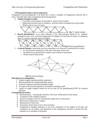
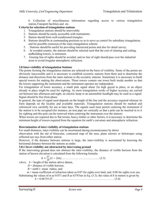
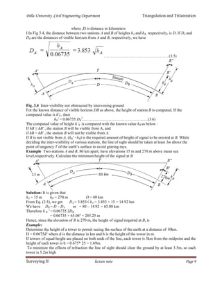
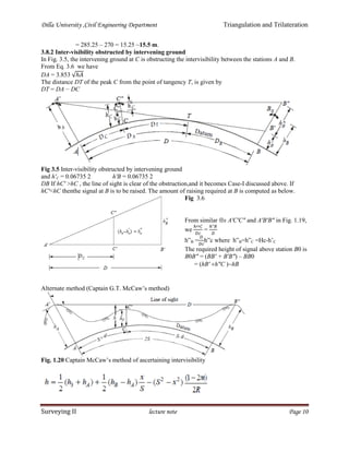
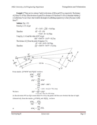
SlideShare a Scribd company logo
1 of 19
Download to read offline
Dilla University ,Civil Engineering Department Triangulation and Trilateration
Surveying II lecture note Page 1
CHAPTER THREE
TRIANGULATION AND TRILATERATION
3.1 General
To prevent accumulation of error it is necessary to provide number of control points all over the area, this
is done by control survey. The determination of the precise position of a number of stations, usually
spread over a large area, is referred to as control surveying. Control surveys can be horizontal or vertical.
The objective of horizontal control surveys is to establish a network of control stations whose position is
specified in terms of latitude and longitude, whereas the objective of vertical control survey is to provide
the elevations of fixed benchmarks with respect to the mean sea level datum. These control surveys are
located where other surveys can be conveniently and accurately tied in to them.
The results of the control surveys are used as a basis from which surveys of smaller extent can be
originated. Boundary surveys, construction, route surveys, topographic and hydrographic surveys and
other may be involved
Methods of horizontal control survey are
 Traverse
 Triangulation
 Trilateration and
 combination of these methods can be used.
Intersection, resection, and satellite positioning are also the other methods in horizontal control surveys.
The exact method used depends of the terrain, equipment available, information needed and economic
factors.
With traversing, a series of horizontal distances and angles are measured. This is generally cheaper due to
shorter sights and convenience to carry it out under less favorable weather conditions than the other
methods. Its disadvantage is that, there are fewer checks available for locating mistakes in the work and
the whole system can rather easily sway or bend. To check a traverse it is necessary to form a loop
returning to its starting point or to tie it in to previously established control points.
A Triangulation consists of a series of joined or overlapping triangles in which an occasional line (called
the base line) is measured and all other sides of the triangles are calculated from angles measured at the
vertices of the triangles. The lines of a triangulation system form a network that ties together all the
triangulation stations at the vertices of the triangles. A triangulation has the following advantages:
1. More redundancies or checks are available (i.e. more than one route can be followed to compute
the length of a line.)
2. There is little tendency for the system to sway or bend (i.e. azimuths can be easily and accurately
carried or established throughout system).
3. Outstanding landmarks such as steeples, water tanks, etc can be located by establishing directions
from different stations.
Its disadvantages are it needs long-range inter-visibility, which in turn requires the erection of special
towers and signals, making the system the most expensive. Moreover, a good weather is required to attain
inter-visibility.
With Trilateration, the lengths of the sides of a series of joined or overlapping triangles are measured
(usually with the EDM equipment) and the angles are computed from the lengths. It has the following
advantages:
1. It is more accurate than the other two types due to the fact that distances can be measured more
accurately than angles.
2. It is generally less expensive than triangulation.
3. More checks are available.
Unlike triangulation, it is not easy to position transmission towers, steeples, water tanks, etc. by the EDM
because to do so requires reflectors on these landmarks. These landmarks can be located if angular
measurements are made to them.
Dilla University ,Civil Engineering Department Triangulation and Trilateration
Surveying II lecture note Page 2
In combined triangulation and trilateration systems all sides and angles in the joined or over lapping
triangles are measured. This method provides the strongest control network
Purpose/objective of triangulation
 For establishment of accurate control points for plane and geodetic survey of large areas
 For establishment of accurate control points photogrammetric survey of large areas
 To assist in determination of the size and shape of the earth
 To determine the accurate location for setting out of engineering works such as piers and
abutments for long-span bridge.
 Fixing of center lines , terminal points ,shafts for long tunnels and measurement of deformation
of dams.
3.2 Triangulation Principles and Uses
 From interconnected triangles measuring the length of first side (baseline ) and angles
other remaining can be calculated trigonometrically.
 If the coordinate and azimuth of any vertices (mostly baseline ) is known ,the
coordinates of the remaining can be calculated through departure and latitude. Latitude is
always measured parallel to meridian or along X-axis while departure is perpendicular to
meridian or along Y-axis .
Purpose/uses of triangulation
 For establishment of accurate control points for plane and geodetic survey of large areas
 For establishment of accurate control points photogrammetric survey of large areas
 To assist in determination of the size and shape of the earth
 To determine the accurate location for setting out of engineering works such as piers and
abutments for long-span bridge.
 Fixing of center lines , terminal points ,shafts for long tunnels and measurement of deformation
of dams.
3.3 Classification of triangulation
Accuracies required for horizontal control depend on the type of survey and the ultimate use of the
control points. There are three orders of triangulation based on their uses:
i. First-order(primary)triangulation is the highest accuracy and is required for developing the
national network of horizontal control, for the study of small crustal movements in areas of
seismic activity, and for large metropolitan control expansion. Since it covers a large area, the
effect of earth’s curvature is to be taken in to account-geodetic triangulation. It may cover the
whole country primary grids may be provided. The triangulation station can be 16km-to-150km
far apart having baseline length of 8km- to-12km.an average error can be up to 1”.
ii. Second order (secondary) triangulation provides point at greater density than first order
triangulation. This network is adjusted to fit its parent primary triangle or its surrounding primary
control. Less refinement is needed as the network is surrounded by the primary control. It is
recommended for controlling extensive land subdivision and construction. The triangulation
station can be 10km-to-25kmhaving baseline length of 2km- to-5km. The average error can be up
to 3”.
iii. Third order (tertiary) triangulations used to establish control for detailed engineering and
location surveys or to provide control points b/n primary and secondary triangulation. Length of
base line can be extended from 100m-to-500m with side length of 2km to 10km. allowable
average error is up to 12”
Dilla University ,Civil Engineering Department Triangulation and Trilateration
Surveying II lecture note Page 3
3.4Triangulation figures and arrangements
Triangulation layout/arrangement is all about how various a triangles of triangulation network laid in
series. Generally there three triangulation layout/arrangements.
1. .Simple Triangles in chain
o Used when control points are provided in narrow strip of terrain
o Rapid and economical due to simplicity and observation of diagonal are not provided
o Mostly used in river surveying
Fig 3.1 simple triangle
2. Braced Quadrilateral as its name indicates it four sided polygon braced by its diagonal
arranged in series .this is the best arrangement of triangles as it provides d/t means of computing
sides. It is mostly used than chain of triangles
Fig 3.2 braced quadrilateral
3. Centered Polygon is used when vast area extending in all direction is required to be covered.
o In this network combination of the above networks can be used
o Generally low in use because it requires more setting of instruments.
o Mostly used for hilly terrain
Fig 3.3 centered polygon
Ideal figures for triangulation
1. Simple triangles should preferably equilateral
2. Braced quadrilaterals should preferably squares
3. Centered polygons should be preferably regular
4. No angle of the network opposite to the baseline should be small
5. Angles of simple triangles should not be less than 450
,for quadrilaterals300
,400
for centered
polygons
Triangulation procedure
1. Reconnaissance: - meaning the selection of the most visible points for the station.
2. Evaluation of the strength of figures;
3. Erection of signals, tower for elevating the signals and /or instruments;
4. Observation of directions or angles;
5. Measurement of base lines;
6. Astronomic observation at one or more locations,
7. Computations including reduction to sea level, calculation of the lengths of all sides and
coordinates for all stations, and adjustment of the triangulation network to provide the best
estimates of co-ordinates of all points.
Dilla University ,Civil Engineering Department Triangulation and Trilateration
Surveying II lecture note Page 4
3.5 Well-Condition Triangle
The accuracy of a triangulation system is greatly affected by the arrangement of triangles in the
layout and the magnitude of the angles in individual triangles. The triangles of such a shape, in which
any error in angular measurement has a minimum effect upon the computed lengths, is known as
well-conditioned triangle.
.
3.6 Strength of Figures
The strength of figure is a factor to be considered in establishing a triangulation system to maintain the
computations within a desired degree of precision. It plays also an important role in deciding the layout of
triangulation system
The strength of figure is a function of:
1. The geometric strength of the triangles that make up the network. Ideally, the triangles should be
equilateral.
2. The number of stations occupied for angle or direction measurements lines occupied at only one
end should be avoided whenever possible.
3. The number of angle and side conditions used in adjusting the network. this number should be
large in proportion to the numbers of observations.
The following equation is used to evaluate the strength of figure:
  


22
BBAA
D
CD
R  ……………………………….(3.1)
Where R = Strength of figure
where
D = the number of directions observed excluding the known side of the figure,
δA ,δB = the difference per second in the sixth place of logarithm of the sine of the distance angles A, B
respectively. (Distance angle is the angle in a triangle opposite to a side), and
C = the number of geometric conditions for side and angle to be satisfied in each figure. It is given by
C = (n' – S' + 1) + (n – 2S + 3) …………………………………...(3.2)
where
n = the total number of lines including the known side in a figure,
n' = the number of lines observed in both directions including the known side,
S = the total number of stations, and
S' = the number of stations occupied.
For the computation of the quantity   
22
BBAA  Table 3.1 may be used .
Example 3.1Compute the value of
D
CD 
for the following triangulation figures if all the lines have
been observed in both directions :
(i) A single triangle
(ii) A braced quadrilateral
(iii) A four-sided central-point figure without
diagonals
(iv) A four-sided central-point figure with one
diagonal.
C = (n' – S' + 1) + (n – 2S + 3)
n' =3 n = 3 S = 3 S' = 3
C = (3 – 3 + 1) + (3 – 2 × 3 + 3) = 1
and D = the number of directions observed excluding the known side.
= 2 (total number of lines – 1) = 2 × (3 – 1) = 4
D
CD 
= 0.75
Dilla University ,Civil Engineering Department Triangulation and Trilateration
Surveying II lecture note Page 5
Dilla University ,Civil Engineering Department Triangulation and Trilateration
Surveying II lecture note Page 6
Example 3.1Compute the value of
D
CD 
for the following triangulation figures if all the lines have
been observed in both directions :
(i) A single triangle
(ii) A braced quadrilateral
(iii) A four-sided central-point figure without diagonals
(iv) A four-sided central-point figure with one diagonal.
Solution: (i) Single triangle (Fig. 1.11)
From Eq. (1.11), we have
C = (n' – S' + 1) + (n – 2S + 3)
n' =3 n = 3 S = 3 S' = 3
C = (3 – 3 + 1) + (3 – 2 × 3 + 3) = 1
and D = the number of directions observed excluding the known side.
= 2 (total number of lines – 1)
= 2 × (3 – 1) = 4
D
CD 
= 0.75
Example 3.2
Compute the strength of figure ABCD for all the routes by which the length CD can be determined from
the known side AB assuming that all the stations have been occupied, and find the strongest rout.
Solution (Fig3.4)
There are four routes by which the length of CD can be computed. These are
Route-1: ∆ABDand∆ BDC having common
side BD
Route-2:∆ ABDand∆ ADC having common
side AD
Route-3:∆ ABCand∆ ADC having common
side AC
Route-4 ∆ ABC and ∆ BCDhaving common
side BC
Fig 3.4
D
CD 
=0.60 for each route the value of   
22
BBAA 
will be calculated or read from table
3.1 as below
Route-1:In ∆ ABD, the distance angles for the sides AB and BD are 28° and(54°+ 46°
=100°), respectively.
δ28= sixth place of decimal of logsin(28o
+1”)-log sin(280
)=3.96
δ100 = sixth place of decimal of logsin. (100° +1′′) − log sin(100° )= -0.37
δ28
2
+ δ28 δ100 + δ100
2
=3.96 2
+3.96*(-0.37)+0.372
=14.34~ 14
In∆ BDC the distance angles for the sides BD and CD are (70°+ 42° = 112°) and 40°,respectively.
δ112 = sixth place of decimal of log sin(112o
+1”) - log sin(1120
) =-0.85
δ40 = sixth place of decimal of logsin. (40° +1′′) − log sin(40° )= -2.51
δ112
2
+ δ112 δ40 + δ40
2
=5
Therefore, Δ1=14+5 = 19 in similar way Δ2, Δ3 and Δ4 for the remaining routes are calculated
Dilla University ,Civil Engineering Department Triangulation and Trilateration
Surveying II lecture note Page 7
Route 2: in ∆ABD the distance angles for the sides AB and AD are 28° and 52°, respectively.
δ 28=3.96 δ52 = 1.65
In ∆ADC the distance angles for the sides AD and CDare 70°and 54°, respectively.
δ 70 =0.77 δ54 = 1.53 , Δ2 = 29
Route-3:In ∆ABC the distance angles for the sides AB and AC are 42° and (52°+ 40° =
92°),respectively. δ 42 =2.34 δ92 = -0.07
In ∆ ADC the distance angles for the sides AC and CD are (28°+ 28° = 56°) and 54°;respectively δ 56
=1.42 δ54 = 1.5 , Δ3 = 12
Route-4:In ∆ABC the distance angles for the sides AB and BC are 42° and 46°, respectively
δ 42 =2.34 δ46 = 2.03
In ∆ BCD the distance angles for the sides BC and CD are 28° and 40°, respectively
δ 28 =3.96 δ40= 2.51 , Δ4 = 46
Thus, R1=0.6 ×∆1= 0.6 × 19 = 11
R2=0.6 ×∆2= 0.6 × 29 = 17
R3=0.6 ×∆3= 0.6 × 12 = 7
R4=0.6 ×∆4= 0.6 × 46 = 28
The route-3 has the minimum value of R = 7, therefore the strongest route
Route Triangle Known
side
Computed
side
Distance angles
∑
22
BBAA   R= 0.6*
ΔiδA δB
1 ABD AB BD 280
1000
14
5 Δ1=19 11BDC BD CD 1120
400
2 ABD AB AD 280
520
25
4 Δ2=29 17ADC AD CD 700
540
3 ABC AB AC 420
920
8
4 Δ3=12 7ADC AC CD 700
540
4 ABC AB BC 420
460
4
32 Δ4=46 28BCD BC CD 280
400
Triangulation survey involves consists of two broad work division (routine)
(a) field work, and (b) computations.
The field work of triangulation is divided into the following operations :
(i) Reconnaissance
(ii) Erection of signals and towers
(iii) Measurement of base line
(iv) Measurement of horizontal angles
(v) Measurement of vertical angles
(vi) Astronomical observations to determine the azimuth of the lines.
3.7 Reconmnaisance and selection of stations
Reconnaissance is the preliminary field inspection of the entire area to be covered by triangulation,
andcollection of relevant data. Since the basic principle of survey is working from whole to the part,
reconnaissance is very important in all types of surveys. It requires great skill, experience and judgement.
The accuracy and economy of triangulation greatly depends upon proper reconnaissance survey. While
selecting triangulatiion statiion things should be considered
1. Examination of terrain to be surveyed.
2. Selection of suitable sites for measurement of base lines.
3. Selection of suitable positions for triangulation stations.
4. Determination of intervisibility of triangulation stations.
5. Selection of conspicuous well-defined natural points to be used as intersected points.
Dilla University ,Civil Engineering Department Triangulation and Trilateration
Surveying II lecture note Page 8
6. Collection of miscellaneous information regarding access to various triangulation
station,Transport facilities and etc.
Criteria for selection of triangulation stations
1. Triangulation stations should be intervisible.
2. Stations should be easily accessible with instruments.
3. Station should form well-conditioned triangles.
4. Stations should be at commanding positions so as to serve as control for subsidiary triangulation,
and for possible extension of the main triangulation scheme
5. . Stations should be useful for providing intersected points and also for detail survey.
6. . In wooded country, the stations should be selected such that the cost of clearing and cutting,
andbuilding towers, is minimum.
7. Grazing line of sights should be avoided, and no line of sight should pass over the industrial
areas to avoid irregular atmospheric refraction.
3.8 Inter-visibility of triangulation Stations
The points forming the triangulation stations are selected on the basis of visibility. Some of the points are
obviously inaccessible and it is necessary to establish eccentric stations from them and to determine the
distance and directions from the main stations to the eccentric stations. Sometimes it is necessary to build
special towers for making the observations. These towers contain one tower built inside another so that
the towers supporting the instrument and the instrument operator are independent.
For triangulation of lower accuracy, a small pole signal about 2m high guyed in place, or an object
already in place might be used for sighting. As most triangulation works of higher accuracy are carried
out between late afternoon and night, an electric lamp or an automobile headlight may be used as a signal.
Signal should be free from phase.
In general, the type of signal used depends on the length of the line and the accuracy required whereas its
form depends on the locality and available materials. Triangulation stations should be marked and
referenced very carefully for use at later days. The signals used must permit centering the instrument if
the station is to be occupied (for instance, an iron pipe set vertically so that a pole can be inserted in to it
for sighting and this pole can be removed when centering the instrument over the station)
When towers are required due to flat terrain, heavy timber or other factors, it is necessary to determine the
minimum height of towers required from the equation for earth’s curvature and atmospheric refraction.
Determination of inter-visibility of triangulation stations
For small distances, inter-visibility can be ascertained during reconnaissance by direct
observation with the aid of binocular, contoured map of the area, plane mirrors or heliotropes using
reflected sun rays from either station.
However, if the distance between stations is large, the inter-visibility is ascertained by knowing the
horizontal distance between the stations as under.
3.8.1 Inver-visibility not obstructed by intervening ground
If the intervening ground does not obstruct the inter-visibility, the distance of visible horizon from the
station of known elevation is calculated from the following formula:
………………………………… (3.3)
where, h = height of the station above datum,
D = distance of visible horizon,
R = earth’s mean radius, and
m = mean coefficient of refraction taken as 0.07 for sights over land, and. 0.08 for sights over sea.
Substituting the values of m as 0.071 and R as 6370 km in Eq. (3.3), the value of h in meters is given by
h = 0.06735 D2
………………………………………………………. (3.4)
Dilla University ,Civil Engineering Department Triangulation and Trilateration
Surveying II lecture note Page 9
where ,D is distance in kilometers
I In Fig 3.4, the distance between two stations A and B of heights hA and hB , respectively, is D. If DA and
DB are the distances of visible horizon from A and B, respectively, we have
………………………………………… (3.5)
Fig. 3.4 Inter-visibility not obstructed by intervening ground
For the known distance of visible horizon DB as above, the height of station B is computed. If the
computed value is h'B , then
hB' = 0.06735 DB
2
……………………………………….….(3.6)
The computed value of height h’B is compared with the known value hB as below :
If hB ≥ hB' , the station B will be visible from A, and
if hB < hB' , the station B will not be visible from A.
If B is not visible from A, (hB' −hB) is the required amount of height of signal to be erected at B. While
deciding the inter-visibility of various stations, the line of sight should be taken at least 3m above the
point of tangency T of the earth’s surface to avoid grazing rays.
Example Two stations A and B, 80 km apart, have elevations 15 m and 270 m above mean sea
level,respectively. Calculate the minimum height of the signal at B.
Solution: It is given that
hA = 15 m hB = 270 m D = 80 km
From Eq. (3.5), we get DA = 3.853√ hA = 3.853 × 15 = 14.92 km
We have DB = D – DA or = 80 – 14.92 = 65.08 km
Therefore h B ' = 0.06735 2DB
= 0.06735 × 65.08² = 285.25 m
Hence, since the elevation of B is 270 m, the height of signal required at B, is
Example:
Determine the height of a tower to permit seeing the surface of the earth at a distance of 10km.
H = 0.0675d2
where d is the distance in km and h is the height of the tower in m.
If towers of equal height are placed on both ends of the line, each tower is 5km from the midpoint and the
height of each tower is h = 0.675* 25 = 1.69m.
To minimize the effects of refraction the line of sight should clear the ground by at least 3.5m, so each
tower is 5.2m high
Dilla University ,Civil Engineering Department Triangulation and Trilateration
Surveying II lecture note Page 10
= 285.25 – 270 = 15.25 ~15.5 m.
3.8.2 Inter-visibility obstructed by intervening ground
In Fig. 3.5, the intervening ground at C is obstructing the intervisibility between the stations A and B.
From Eq. 3.6 we have
DA = 3.853 √
The distance DT of the peak C from the point of tangency T, is given by
DT = DA − DC
Fig 3.5 Inter-visibility obstructed by intervening ground
and h'C = 0.06735 2 h'B = 0.06735 2
DB If hC' >hC , the line of sight is clear of the obstruction,and it becomes Case-I discussed above. If
hC'<hC thenthe signal at B is to be raised. The amount of raising required at B is computed as below.
Fig 3.6
From similar s A'C'C" and A'B'B" in Fig. 1.19,
we =
h”B = h”c where h”B=h”C =Hc-h’C
The required height of signal above station B0 is
B0B" = (BB' + B'B") – BB0
= (hB' h"C )hB
Alternate method (Captain G.T. McCaw’s method)
Fig. 1.20 Captain McCaw’s method of ascertaining intervisibility
Dilla University ,Civil Engineering Department Triangulation and Trilateration
Surveying II lecture note Page 11
Dilla University ,Civil Engineering Department Triangulation and Trilateration
Surveying II lecture note Page 12
3.9. Signals and phase of signals
3.9.1 SIGNALS
Signals are centered vertically over the station mark, and the observations are made to these signals from
other stations. The accuracy of triangulation is entirely dependent on the degree of accuracy of centering
the signals. Therefore, it is very essential that the signals are truly vertical, and centered over the station
mark. Greatest care of centering the transit over the station mark will be useless, unless some degree of
care in centering the signal is impressed upon. Classification of signals
The signals may be classified as under :
1.Non-luminous, opaque or daylight signals Non-luminous signals are used during day time and for
short distances. These are of various types, and
the most commonly used are of following types like Pole signal, Target signal, Pole and brush signal,
Stone cairn
2. Luminous signals. Luminous signals may be classified into two types :
i. Sun signals:- Sun signals reflect the rays of the suntowards the station of observation, and are also
known as heliotropes. Such signals can be used only in day time in clear weather
ii. Night signals: When the observations are required to be made at night.
3.9.2 Phase of Signal
When cylindrical opaque signals are used, they require a correction in the observed horizontal angles due
an error known as the phase. The cylindrical signal is partly illuminated by the sun, and the other part
remains in shadow, and becomes invisible to the observer. While making the observations, the observer
may bisect the bright portion or the bright line. Thus the signal is not bisected at the centre, and an error
due to wrong bisection is introduced. It is, thus, the apparent displacement of the signal. The phase
correction is thus necessary so that the observed horizontal angles may be reduced to that corresponding
to the centre of thesignal.Depending upon the method of observation, phase correction is computed under
the following two conditions.
 Observation made on bright portion
 Observations made on the bright line
3.10 Base Line Measurement
The accuracy of an entire triangulation system depends on that attained in the measurement of the base
line and, therefore, the measurement of base line forms the most important part of the triangulation
operations. As base line forms the basis for computations of triangulation system it is laid down with
great accuracy in its measurement and alignment.The following points should be taken into consideration
while selecting the site for a base line.
 The site should be level or of uniform slope
 Ground should be free of obstruction through out the length of the base line
 The extremities of the base line should b e inter-visible
 The network of triangle formed should be well-conditioned
Equipment for base line measurement
Generally the following types of base measuring equipments are used
1. Standardized tapes: for measuring short bases in plain grounds.
2. . Tachometric base measurements : It is used in undulating grounds for small bases
3. Electronic distance measurement(EDM)
If base line is measured by standard tapes after having measured the length the correct length of the base
is calculated by applying the required corrections. The following five corrections may be found for the
measured lengths of tape:
(i) Corrections for absolute length
(ii) Corrections for pull
Dilla University ,Civil Engineering Department Triangulation and Trilateration
Surveying II lecture note Page 13
(iii) Corrections for temperature
(iv) Corrections for slope and
(v) Corrections for sag.
If the triangulation system is of extensive nature, the corrected lengths of the base are reduced to the
mean sea level.
3.11 Adjustment of Triangulation networks
The primary objective of triangulation is to determine the co-ordinates of the triangulation stations for
further surveys. Before computations of the positions carried out, the net should be adjusted as follows.
1. All baselines have to be corrected for systematic errors and reduced to sea level distances;
2. Observed directions and angles should be reduced to average values and triangles checked for
closure;
3. Necessary reductions to center should be made where eccentric stations have been occupied;
4. Spherical excess should be computed where lines and triangles are of sufficient length. In the
adjustment process, the following conditions have to be satisfied:
(1)Angle conditions (2) side conditions (3) length conditions (4) azimuth conditions and (5) position
conditions. There as two methods of adjustment:
1. The approximate method and 2. The least square method.
3.11.1 Triangulation Adjustment by the Approximate Method
Connections in triangulation nets can be either by means of triangles or quadrilaterals, or by a
combination of different kinds of figures. When triangles are used the only adjustment to be made is to
satisfy the condition that the sum of the three angles of each triangle should equal 1800
plus any spherical
excess. The adjustment is made ordinarily by correcting each angle by one – third of the closure in that
triangle. Although the work involved is simple, the only check on the computed lengths is afforded by
measuring additional base lines.
When quadrilaterals are used, additional checks on angular measurements are provided by the added
geometric conditions in each figure. Checks on the computed lengths are afforded by following four
different combinations of triangles in each quadrilateral. Unless the measured angles have been adjusted,
it is unlikely that the four computed lengths will agree exactly. The purpose of the adjustment is to correct
the observed angles so that the various conditions relative to the sums of the angles will be satisfied, and
in addition, so that the computed lengths of a side will have the same numerical value regardless of the
triangles used in the computation
In the quadrilateral shown in fig the sum of the
eight angles should equal 3600
, and the sum of
the three angles of any one triangle should equal
1800
, ignoring the spherical excess. In addition,
b + c = g + f, and a + h = d + e. The side
condition can be developed as follows
Fig. 3.6
In triangle ABC, BC = AB
e
b
sin
sin
In triangle BCD, CD =
e
d
BC
sin
sin
ge
db
AB
sinsin
sinsin

In triangle CDA, DA = CD
gea
fdb
AB
a
f
sinsinsin
sinsinsin
sin
sin

Dilla University ,Civil Engineering Department Triangulation and Trilateration
Surveying II lecture note Page 14
In triangle DAB,
geca
hfdb
AB
c
h
DAAB
sinsinsinsin
.sinsinsinsin
sin
sin

Hence,
geca
hfdb
sinsinsinsin
sinsinsinsin
1 Taking the logarithms of both sides of the equation,
(log sin b + log sin d + log f + log sin h) - (log sin a + log sin c + log sin e + log sin g) = 0
Example:
Adjust the quadrilateral shown below by the approximate method. All angles are observed with equal
precision.
Angle Value
1 270
02’12.6’’
2 530
41’ 09.3’’
3 550
25’25.1’’
4 430
51’17.0’’
5 560
11’57.3’’
6 240
31’25.2’’
7 390
53’01.4’’
8 590
23’35.7’’
SolutioSum of the eight angles in the quadrilateral = 3600
00’03.6”
Correction to each angle for 3600
= 3.6’’/ 8 = 0.45’’
Sum of opposite angles (1 + 2) = (5 + 6)
1+2 = 800
43’21’’ 5+6=800
43’21.6’’
Correction to be applied to these angles = 0.6’’ / 4 =0.15’’(to be added to 1 and 2, and deducted from 5
and 6).
Sum of opposite angles (3+4) = (7+8)
3+4 = 990
16’41.20’’; 7+8 = 990
16’36.20’’
Correction to be applied to these angles = 5’’ /4 = 0.125’’(to be added to 7 and 8, and subtracted from 3
and 4).
The side condition equation is developed as
(log sin 1+log sin 3+log sin 5+log sin 7)-(log sin 2+log sin 4+log sin 6+log sin 8) = 0
The solution is effected by using the method indicated in the table below. The sums of the log sins of
alternate angles adjusted for angular closure are found as in column 4.
Difference between sums of log sins of alternate angles = 0.00001205
The sums of the alternate log sines fail to agree by 120.5 in seven place values, and hence the angles must
be corrected by the amount that will eliminate this difference. The change must be effected by correcting
each by equal amount in order to keep the sum at 3600
and to keep the sums of opposite angles equal.
The value of the correction in seconds is found by dividing the total change in log sines by the total
difference in log sines for 1’’ of angle. total change in log sines by the total difference in log sines for 1’’
of angle.
3.11.2 Triangulation Adjustment by the Least squares Method: condition Equations
In a completed quadrilateral with six sides and eight angles observed, the conditions to be satisfied are (1)
the angles in any three of the four triangles must add up to 1800
plus spherical excess, and (2) the angles
of the closing side of the quadrilateral must be the same no matter which way it is computed. The method
of condition equations for the adjustment of the quadrilateral is explained by a specimen problem.
B A
D
6
7
C
3
2
4
5
1
8
Dilla University ,Civil Engineering Department Triangulation and Trilateration
Surveying II lecture note Page 15
Example Adjust the quadrilateral in the example given previously by the method of condition equations.
Solution:
Let the residuals of the measured angles 1 through 8 be v1, v2 v3 v4 v5 v6 v7 and v8 respectively.
The resulting angles including the correction are
1. 270
02’12.6’ + v1
2. 530
41’09.3’’+ v2
3. 550
25’25..1’’+v3
4. 430
51’17.0’’ + v4
5. 560
11’57.3’’ +v5
6. 240
31’25.2’’+v6
7. 390
53’01.4’+ v7
8. 590
23’35.7’’+v8
Considering angle conditions of three of the four triangles
Triangle ABC, A 270
02’12.6’’+ v1
B 530
41’09.3’’+ v2 + 550
25’25.1’’ + v3
C 430
51’17.0 + v4 1800
00’04.0’’ + v1 +v2+ v3 + v4 = 1800
00’00.0’’
Triangle BCD, B550
25’25.1+v3
C 430
51’17.0’’+ v4 + 560
11’57.3’’ + v5
D 240
31’25.2’’ + v6
1800
00’04.6’’ + v3 + v4 + v5+ v6 = 1800
00’00.0’’
(1) (2) (3) (4) (5) (6) (7) (8)
Stati
on
(angl
es)
Observed
angles
For 3600 For
opp.
angles
Log sine of
adj. angles
Difference of
logsines for 1”
Corrected
angles
Corrected
logsines
1
270
02’12.6
”
12.15” 12.30” -0.342406963
0.000004125 12.93” -
0.34240403
63
2 530
41’9.3” 08.85” 09.00” -0.093782503
0.000001547 08.37” -
0.09378347
8
3
550
25’25.1
”
24.65” 23.40” -0.084407123
0.000001450 24.03” -
0.08440620
9
4
430
51’17.0
”
16.55” 15.30” -0.159375662
0.000002191 14.67” -
0.15937704
3
5
560
11’57.3
”
56.85” 56.70” -0.080411744
0.000001409 57.33” -
0.08041085
6
6
240
31’25.2
”
42.75” 24.60” -0.381882389
0.000004614 23.97” -
0.38188529
7
7 390
53 ’01.4 00.95” 02.20” -0.192983031
0.000002518 02.83” -
0.19298144
4
8
590
23’35.7’
’
35.25” 36.50” -0.065156257
0.000001245 35.87” -
0.06515704
2
3600
0’
03.6”
00.00” 00.00”
-0.700208862
-0.700196812

=0.000019099
00.00” -
0.70020873
Dilla University ,Civil Engineering Department Triangulation and Trilateration
Surveying II lecture note Page 16
Triangle CDA, C 560
11’57.3’’ + V5
D 240
31’25.2 + V6 + 390
53’01.4’’ + V7
A 590
23’35.7’’ + V8
1790
59’59.6’’ + V5 + V6 + V7 + V8 = 1800
00’00.0’’
From the three conditions we have,
V1 + V2 + V3 + V4 + 4,0 = 0 (1)
V3 + V4 + V5 + V6 + 4.6 = 0 (2)
V5 + V6 + V7 + V8 - 0.4 = 0 (3)
The side condition can be developed in a number of ways:
1. Considering all the four triangles ABC, BCD, CDA and DAB in turn
8sin6sin4sin2sin
7sin5sin3sin1sin
1
2.
 
 
5sin
76sin
;
2sin
7sin
;
32
4 



AD
AC
AD
AB
Sin
Sin
AC
AB
 1 =
 
  7sin5sin32sin
76sin4sin2sin


Angles 1 and 8 are omitted here.
3.
 
 
3sin
54sin
;
5sin
8sin
;
81sin
2sin 



CD
DB
DA
CD
BD
DA
 1 =
 
 81sin5sin3sin
8sin54sin2sin


Angles 6 and 7 ar omitted here.
4.
 
 
1
32
;
3
6
;
76
8
Sin
Sin
BC
CA
Sin
Sin
CD
BC
Sin
Sin
CA
CD 


 
 
 76sin3sin1sin
8sin6sin32sin
1



Angle s4 and 5 are omitted here.
5.
 
 
6sin
54sin
;
81sin
7sin
;
4sin
1sin 



BC
BD
BD
BA
AB
BC  
 81sin6sin4sin
7sin54sin1sin
1



Angles 2 and 3 are omitted here. The selection of one of the five sets is in such a manner as to make the
constant term in the side condition equation as large as possible. For this, the set that contains the
smallest combination of angles is chosen. In this specific problem, set 5 is selected because the
sum of the omitted angles 2 and 3 is larger than the sum of the two angles any other station
Sin 1 sin(4+5) sin 7=sin 4 sin 6 (1+8)
Taking the logarithm of both sides
log sin 1 + log sin (4+5) + log sin 7 = log sin 4 +log sin 6 + log sin (1+8)
In order to make a condition equation, the corrections to the angles are included.
log sin (1 + v1) + log sin (4 + 5 + v4 + v5) + log sin (7+v7)=
log sin (4 + v4) + log sin (6 +V6) + log sin (1 + 8 + V1 + V8)
If the corrections are in seconds, each logarithm can be expressed in a more convenient form, as for
instance,
log sin (1 +V1) = log sin 1 +(change in value of log sin 1 per second)*V1
log sin (1+V1) = -0.342405725 + 4. 126*10-6
V1
log sin (4+5 +V4 + V7) = -0.00672087551 –0.373*10-6
V4 -0.373*10-6
V5
log sin (7 + V7) = -0.192985047 + 2.520* 10-6
V7
-0.542111647 + 10-6
(4.126v1 – 0.373v4 – 0.373v5+2.520v7)
Dilla University ,Civil Engineering Department Triangulation and Trilateration
Surveying II lecture note Page 17
log sin (4 + V4)= -0.159371936 + 2.191* 10-6
V4
log sin (6+V6) = -0.38187962 + 4.615*10-6
V6
log sin (1+8 + V1 + V8) = -0.000843514 + 0.131*10-6
v1+0.131*10-6
v8
-0.54209507 + 10-6
(2.191v4 + 4.615v6 +0. 131v1 + 0.131v8)
Transposing all terms to the left and simplifying, we have
3.995v1 – 2.564v4 – 0.373v5 – 4.615v6 + 2.52v7 – 0.138v8 – 16.577 = 0 (4)
Equations 1 through 4 form the four condition equations.
If we assume that all angles are measured with equal precision, the weight given to each angle is unity and
hence ∑V2
must be a minimum in order to arrive at the most probable values for the angles in the
solution .Hence
V1
2
+V2
2
+V3
2
+V4
2
+V5
2
+V6
2
+V7
2
+V8
2
= minimum (5)
The four condition equations contain eight unknowns resulting in no unique solution. The condition of least
squares allows us to find a unique set of V’s that satisfy the four condition equations. Let the four
condition equations be multiplied by constants C1, C2, C3, and C4, respectively, known as
Lagrange multipliers.
C1 (V1 + V2 + V3 + V4 + 4.0) = 0 (1a)
C2 (V3 + V4 + V5 + V6 + 4.6) = 0 (2a)
C3 (V5 + V6 + V7 + V8 - 0.4) = 0 (3a)
C4 (3.995V1 – 2.564V4 – 0.373V5 – 4.615V6 + 2.52V7 – 0.138V8 – 16.577) = 0(4a)
Adding the left-hand side of the four equations and differentiating with respect to the variables we get,
dv1(C1 + 3.995C4) + dv2(C1) + dv3 (C1 + C2) + dv4 (C1 + C2 – 2.564C4) + dv5 (C2 + C3 –0.373C4) + dv6 (C2
+ C3 – 4.615C4) + dv7(C3 + 2.52C4 )+ dv8 (C3 – 0.131C4) – 16.577 = 0
Differentiating equation 5 and comparing to that above result, we get
V1 = C1 + 3.995C4
V2 = C1
V3 = C1 + C2
V4 = C1 + C2 – 2.564C4
V5 = C2 + C3 – 0.373C4
V6 = C2 + C3- 4.615CC
V7 = C3 + 2.52C4
V8 = C1 – 0.131C4
Substituting for V’s back into equations 1 through 4, we get
4C1 + 2C2 + 1.431C4 + 4 = 0
4C1 + 4C2 – 7,552C4 + 4.6 =0
2C2 + 4C3 – 2606C4 – 0.4 =0
1.431 C1 –7.552C2 – 2.606C3 + 50.341C4 – 16.577 = 0
Solving the above equation simultaneously,
C1 = - 1.33 C2= 0.226 C3 = 0.299 C4 = 0.423
Solving for V’s,
V1=0.39
V2 =-1.30
V3 =-1.00’’
V4 =-2.09’’
V5 =0.37’’
V6 =-1.42’’
V7 =1.29’’
V8 =0.17’’
3.12 Triangulation Computation
Computation of lengths
Two sides of each triangle are computed by the law of sines, since one side of the triangle is always
known and the three angles have been measured and adjusted. In computing the sides of the triangles in a
quadrilateral, the solution of the two triangles is sufficient to compute the position of the forward
triangulation stations. The two triangles chosen must be the strongest route through the quadrilateral.To
check the accuracy of the fieldwork or the consistency of the figure after adjustment, computations the
Dilla University ,Civil Engineering Department Triangulation and Trilateration
Surveying II lecture note Page 18
forward triangulation stations can be repeated through the second-best strong routes. However, only the
results for the strongest route will be used in further computations.
Example:
Compute the lengths of sides of the triangles in order to determine the positions of the forward station
given that the length of AB is 1192.938m in the example above.
Solution
Here the angles adjusted by the approximate method are used to compute the lengths of the sides of the
triangles.
1. Compute the strength of figures for the four possible combinations of triangles following the
method discussed. The strongest chain is through triangles CBA and DCA (R1 = 4.536), followed
by the chain through triangles DAB and CDB (R2 =5.4).
2. Write the formula used to compute the desired sides. Computation is carried out through the
strongest route (CBA and DCA), but to provide a check on the computations, it is repeated
through the second-strongest route (DAB and CDB).
Dilla University ,Civil Engineering Department Triangulation and Trilateration
Surveying II lecture note Page 19
Computation of positions
The objective of triangulations is to establish the horizontal positions of the triangulation stations in the
network relative to one another and with respect to the horizontal datum. The network must include at
least one point, and preferably two or more points, the horizontal position of which is known with respect
to a national datum, or co-ordinate system.
If the co-ordinates of two stations A and B are known, the length of the line AB, LAB, calculated from
 22
)( ABABAB YYXXL 
is used as a starting line in the computations of the lengths of the quadrilateral. The azimuth from the
north of the line AB, AABN, is computed from,
AB
AB
AB
YY
XX
A N


 1
tan
Where X A ,X B ,Y A ,and Y B are the X- and Y- co-ordinates of A and B ,respectively

More Related Content

What's hot

9. MORDAN SURVEYING INSTRUMENTS (SUR) 3140601 GTU
9. MORDAN SURVEYING INSTRUMENTS (SUR) 3140601 GTU9. MORDAN SURVEYING INSTRUMENTS (SUR) 3140601 GTU
9. MORDAN SURVEYING INSTRUMENTS (SUR) 3140601 GTUVATSAL PATEL
 
EDM ( Electronic distance meter)
EDM ( Electronic distance meter)EDM ( Electronic distance meter)
EDM ( Electronic distance meter)Umarfarook Momin
 
Traverse Survey Part 1/2
Traverse Survey Part 1/2Traverse Survey Part 1/2
Traverse Survey Part 1/2Muhammad Zubair
 
Theodolite traversing, purpose and principles of theodolite traversing
Theodolite traversing, purpose and principles of theodolite traversingTheodolite traversing, purpose and principles of theodolite traversing
Theodolite traversing, purpose and principles of theodolite traversingDolat Ram
 
Geodetic surveying - Assignment
Geodetic surveying - AssignmentGeodetic surveying - Assignment
Geodetic surveying - AssignmentVijay Parmar
 
Ce6304 surveying 1 contour (iv unit) lecture ppt notes
Ce6304 surveying 1   contour (iv unit) lecture ppt notesCe6304 surveying 1   contour (iv unit) lecture ppt notes
Ce6304 surveying 1 contour (iv unit) lecture ppt notesnandishsajjan
 
Introduction to surveying
Introduction to surveyingIntroduction to surveying
Introduction to surveyingMir Zafarullah
 
Contour & Contouring Surveying
Contour & Contouring SurveyingContour & Contouring Surveying
Contour & Contouring SurveyingBahzad5
 
Surveying ii module iii class 1,2
Surveying ii module iii class 1,2Surveying ii module iii class 1,2
Surveying ii module iii class 1,2SHAMJITH KM
 
Tacheometric surveying ppt
Tacheometric surveying pptTacheometric surveying ppt
Tacheometric surveying pptNaufil Sayyad
 
Advanced surveying instruments
Advanced surveying instrumentsAdvanced surveying instruments
Advanced surveying instrumentsAjeykumar VG
 
Advance surveying equipments
Advance surveying equipmentsAdvance surveying equipments
Advance surveying equipmentsRanjan Kumar Lal
 

What's hot (20)

9. MORDAN SURVEYING INSTRUMENTS (SUR) 3140601 GTU
9. MORDAN SURVEYING INSTRUMENTS (SUR) 3140601 GTU9. MORDAN SURVEYING INSTRUMENTS (SUR) 3140601 GTU
9. MORDAN SURVEYING INSTRUMENTS (SUR) 3140601 GTU
 
Control surveying
Control surveyingControl surveying
Control surveying
 
Surveying ch-two
Surveying ch-twoSurveying ch-two
Surveying ch-two
 
EDM ( Electronic distance meter)
EDM ( Electronic distance meter)EDM ( Electronic distance meter)
EDM ( Electronic distance meter)
 
GPS Surveying
GPS SurveyingGPS Surveying
GPS Surveying
 
Traverse Survey Part 1/2
Traverse Survey Part 1/2Traverse Survey Part 1/2
Traverse Survey Part 1/2
 
Theodolite traversing, purpose and principles of theodolite traversing
Theodolite traversing, purpose and principles of theodolite traversingTheodolite traversing, purpose and principles of theodolite traversing
Theodolite traversing, purpose and principles of theodolite traversing
 
Geodetic surveying - Assignment
Geodetic surveying - AssignmentGeodetic surveying - Assignment
Geodetic surveying - Assignment
 
Ce6304 surveying 1 contour (iv unit) lecture ppt notes
Ce6304 surveying 1   contour (iv unit) lecture ppt notesCe6304 surveying 1   contour (iv unit) lecture ppt notes
Ce6304 surveying 1 contour (iv unit) lecture ppt notes
 
Introduction to Aerial Photogrammetry
Introduction to Aerial PhotogrammetryIntroduction to Aerial Photogrammetry
Introduction to Aerial Photogrammetry
 
Curves
CurvesCurves
Curves
 
Introduction to surveying
Introduction to surveyingIntroduction to surveying
Introduction to surveying
 
Compass surveying
Compass surveyingCompass surveying
Compass surveying
 
Total station
Total station Total station
Total station
 
Contour & Contouring Surveying
Contour & Contouring SurveyingContour & Contouring Surveying
Contour & Contouring Surveying
 
tacheometry surveying
tacheometry surveyingtacheometry surveying
tacheometry surveying
 
Surveying ii module iii class 1,2
Surveying ii module iii class 1,2Surveying ii module iii class 1,2
Surveying ii module iii class 1,2
 
Tacheometric surveying ppt
Tacheometric surveying pptTacheometric surveying ppt
Tacheometric surveying ppt
 
Advanced surveying instruments
Advanced surveying instrumentsAdvanced surveying instruments
Advanced surveying instruments
 
Advance surveying equipments
Advance surveying equipmentsAdvance surveying equipments
Advance surveying equipments
 

Viewers also liked

EXT 501 - Triangulation Presentation
EXT 501 - Triangulation Presentation EXT 501 - Triangulation Presentation
EXT 501 - Triangulation Presentation Joanna Wiebe
 
Triangulación
TriangulaciónTriangulación
TriangulaciónnAyblancO
 
Triangulacion y categorizacion
Triangulacion y categorizacionTriangulacion y categorizacion
Triangulacion y categorizacionEver Peña Leiva
 
Qualitiative data analysis: data triangulation
Qualitiative data analysis: data triangulationQualitiative data analysis: data triangulation
Qualitiative data analysis: data triangulationAgnieszka Szóstek
 
Triangulación doc
Triangulación docTriangulación doc
Triangulación docnAyblancO
 
Triangulation methods Mihaylova
Triangulation methods MihaylovaTriangulation methods Mihaylova
Triangulation methods MihaylovaZlatka Mihaylova
 
2010 mcm predictions of locations of the crimes based on geographical profile
2010 mcm predictions of locations of the crimes based on geographical profile2010 mcm predictions of locations of the crimes based on geographical profile
2010 mcm predictions of locations of the crimes based on geographical profileyangliuyouxiang
 
Trilateration Calculation Program for Location Tracking System
Trilateration Calculation Program for Location Tracking SystemTrilateration Calculation Program for Location Tracking System
Trilateration Calculation Program for Location Tracking SystemNiko Simon
 
Hydrographic survey for std not print
Hydrographic survey for std not printHydrographic survey for std not print
Hydrographic survey for std not printGokul Saud
 
TRIP GENERATION Survey and ORIGIN / DESTINATION STUDY
TRIP GENERATION Survey and ORIGIN / DESTINATION STUDYTRIP GENERATION Survey and ORIGIN / DESTINATION STUDY
TRIP GENERATION Survey and ORIGIN / DESTINATION STUDYGrant Johnson, PE
 
Traffic & transportation – ii
Traffic & transportation – iiTraffic & transportation – ii
Traffic & transportation – iiprahlad reddy
 

Viewers also liked (20)

Triangulation
TriangulationTriangulation
Triangulation
 
EXT 501 - Triangulation Presentation
EXT 501 - Triangulation Presentation EXT 501 - Triangulation Presentation
EXT 501 - Triangulation Presentation
 
Triangulación
TriangulaciónTriangulación
Triangulación
 
Triangulacion y categorizacion
Triangulacion y categorizacionTriangulacion y categorizacion
Triangulacion y categorizacion
 
Qualitiative data analysis: data triangulation
Qualitiative data analysis: data triangulationQualitiative data analysis: data triangulation
Qualitiative data analysis: data triangulation
 
Triangulación doc
Triangulación docTriangulación doc
Triangulación doc
 
Triangulation methods Mihaylova
Triangulation methods MihaylovaTriangulation methods Mihaylova
Triangulation methods Mihaylova
 
Triangulation
TriangulationTriangulation
Triangulation
 
2010 mcm predictions of locations of the crimes based on geographical profile
2010 mcm predictions of locations of the crimes based on geographical profile2010 mcm predictions of locations of the crimes based on geographical profile
2010 mcm predictions of locations of the crimes based on geographical profile
 
Hydrographicsurveying
HydrographicsurveyingHydrographicsurveying
Hydrographicsurveying
 
09 triangulation
09 triangulation09 triangulation
09 triangulation
 
Fce 552 part1
Fce 552 part1Fce 552 part1
Fce 552 part1
 
Trilateration Calculation Program for Location Tracking System
Trilateration Calculation Program for Location Tracking SystemTrilateration Calculation Program for Location Tracking System
Trilateration Calculation Program for Location Tracking System
 
Indoor positioning
Indoor positioningIndoor positioning
Indoor positioning
 
GEODETIC Least Square with fx 991-es plus
GEODETIC Least Square with fx 991-es plusGEODETIC Least Square with fx 991-es plus
GEODETIC Least Square with fx 991-es plus
 
Astronomical surveying
Astronomical surveyingAstronomical surveying
Astronomical surveying
 
Hydrographic survey for std not print
Hydrographic survey for std not printHydrographic survey for std not print
Hydrographic survey for std not print
 
TRIP GENERATION Survey and ORIGIN / DESTINATION STUDY
TRIP GENERATION Survey and ORIGIN / DESTINATION STUDYTRIP GENERATION Survey and ORIGIN / DESTINATION STUDY
TRIP GENERATION Survey and ORIGIN / DESTINATION STUDY
 
Traffic & transportation – ii
Traffic & transportation – iiTraffic & transportation – ii
Traffic & transportation – ii
 
O & d survey
O & d survey O & d survey
O & d survey
 

Similar to Lecture note triangulation_and_trilatera2016

7. GEODETIC SYRVEYING (SUR) 3140601 GTU
7. GEODETIC SYRVEYING (SUR) 3140601 GTU7. GEODETIC SYRVEYING (SUR) 3140601 GTU
7. GEODETIC SYRVEYING (SUR) 3140601 GTUVATSAL PATEL
 
Triangulation survey (Basic Mine Surveying)_MI10412MI.pptx
Triangulation survey (Basic Mine Surveying)_MI10412MI.pptxTriangulation survey (Basic Mine Surveying)_MI10412MI.pptx
Triangulation survey (Basic Mine Surveying)_MI10412MI.pptxRomil Mishra
 
Engineering surveying-ii
Engineering surveying-iiEngineering surveying-ii
Engineering surveying-iiMarvin Ken
 
TOTAL STATION: THEORY, USES AND APPLICATIONS.
TOTAL STATION: THEORY, USES AND APPLICATIONS. TOTAL STATION: THEORY, USES AND APPLICATIONS.
TOTAL STATION: THEORY, USES AND APPLICATIONS. Ahmed Nassar
 
UNIT 1_Chapter 2_Adv Survey.pptx
UNIT 1_Chapter 2_Adv Survey.pptxUNIT 1_Chapter 2_Adv Survey.pptx
UNIT 1_Chapter 2_Adv Survey.pptxMrunmayee Manjari
 
lecture_1a.ppt
lecture_1a.pptlecture_1a.ppt
lecture_1a.pptArisamTom
 
Site surveying-2-done-1
Site surveying-2-done-1Site surveying-2-done-1
Site surveying-2-done-1Lam Yu
 
Site surveying 2 done
Site surveying 2   done Site surveying 2   done
Site surveying 2 done w ss
 
S2 5 traverses
S2 5 traversesS2 5 traverses
S2 5 traversesEst
 
Surveying and levelling
Surveying and levellingSurveying and levelling
Surveying and levellingParimal Jha
 
Wall Station Surveys
Wall Station SurveysWall Station Surveys
Wall Station Surveysbrett_grocock
 
Frank smith final presentation
Frank smith final presentationFrank smith final presentation
Frank smith final presentationbrett_grocock
 
Distance Measurement & Chain Surveying
Distance Measurement & Chain SurveyingDistance Measurement & Chain Surveying
Distance Measurement & Chain SurveyingBahzad5
 
Classification of triangulation
Classification of triangulationClassification of triangulation
Classification of triangulationFayaz Ahamed A P
 

Similar to Lecture note triangulation_and_trilatera2016 (20)

Surveying 2
Surveying   2Surveying   2
Surveying 2
 
7. GEODETIC SYRVEYING (SUR) 3140601 GTU
7. GEODETIC SYRVEYING (SUR) 3140601 GTU7. GEODETIC SYRVEYING (SUR) 3140601 GTU
7. GEODETIC SYRVEYING (SUR) 3140601 GTU
 
Triangulation survey (Basic Mine Surveying)_MI10412MI.pptx
Triangulation survey (Basic Mine Surveying)_MI10412MI.pptxTriangulation survey (Basic Mine Surveying)_MI10412MI.pptx
Triangulation survey (Basic Mine Surveying)_MI10412MI.pptx
 
Engineering surveying-ii
Engineering surveying-iiEngineering surveying-ii
Engineering surveying-ii
 
TOTAL STATION: THEORY, USES AND APPLICATIONS.
TOTAL STATION: THEORY, USES AND APPLICATIONS. TOTAL STATION: THEORY, USES AND APPLICATIONS.
TOTAL STATION: THEORY, USES AND APPLICATIONS.
 
UNIT 1_Chapter 2_Adv Survey.pptx
UNIT 1_Chapter 2_Adv Survey.pptxUNIT 1_Chapter 2_Adv Survey.pptx
UNIT 1_Chapter 2_Adv Survey.pptx
 
BCE U3.pptx
BCE U3.pptxBCE U3.pptx
BCE U3.pptx
 
lecture_1a.ppt
lecture_1a.pptlecture_1a.ppt
lecture_1a.ppt
 
Fw2
Fw2Fw2
Fw2
 
Site surveying-2-done-1
Site surveying-2-done-1Site surveying-2-done-1
Site surveying-2-done-1
 
Site surveying 2 done
Site surveying 2   done Site surveying 2   done
Site surveying 2 done
 
Monitoring Open Pit
Monitoring Open PitMonitoring Open Pit
Monitoring Open Pit
 
S2 5 traverses
S2 5 traversesS2 5 traverses
S2 5 traverses
 
Surveying and levelling
Surveying and levellingSurveying and levelling
Surveying and levelling
 
30838893 chain-survey
30838893 chain-survey30838893 chain-survey
30838893 chain-survey
 
chain surveying
chain surveyingchain surveying
chain surveying
 
Wall Station Surveys
Wall Station SurveysWall Station Surveys
Wall Station Surveys
 
Frank smith final presentation
Frank smith final presentationFrank smith final presentation
Frank smith final presentation
 
Distance Measurement & Chain Surveying
Distance Measurement & Chain SurveyingDistance Measurement & Chain Surveying
Distance Measurement & Chain Surveying
 
Classification of triangulation
Classification of triangulationClassification of triangulation
Classification of triangulation
 

Recently uploaded

High Profile Call Girls Nagpur Isha Call 7001035870 Meet With Nagpur Escorts
High Profile Call Girls Nagpur Isha Call 7001035870 Meet With Nagpur EscortsHigh Profile Call Girls Nagpur Isha Call 7001035870 Meet With Nagpur Escorts
High Profile Call Girls Nagpur Isha Call 7001035870 Meet With Nagpur Escortsranjana rawat
 
GDSC ASEB Gen AI study jams presentation
GDSC ASEB Gen AI study jams presentationGDSC ASEB Gen AI study jams presentation
GDSC ASEB Gen AI study jams presentationGDSCAESB
 
Architect Hassan Khalil Portfolio for 2024
Architect Hassan Khalil Portfolio for 2024Architect Hassan Khalil Portfolio for 2024
Architect Hassan Khalil Portfolio for 2024hassan khalil
 
Analog to Digital and Digital to Analog Converter
Analog to Digital and Digital to Analog ConverterAnalog to Digital and Digital to Analog Converter
Analog to Digital and Digital to Analog ConverterAbhinavSharma374939
 
College Call Girls Nashik Nehal 7001305949 Independent Escort Service Nashik
College Call Girls Nashik Nehal 7001305949 Independent Escort Service NashikCollege Call Girls Nashik Nehal 7001305949 Independent Escort Service Nashik
College Call Girls Nashik Nehal 7001305949 Independent Escort Service NashikCall Girls in Nagpur High Profile
 
Porous Ceramics seminar and technical writing
Porous Ceramics seminar and technical writingPorous Ceramics seminar and technical writing
Porous Ceramics seminar and technical writingrakeshbaidya232001
 
Introduction and different types of Ethernet.pptx
Introduction and different types of Ethernet.pptxIntroduction and different types of Ethernet.pptx
Introduction and different types of Ethernet.pptxupamatechverse
 
Microscopic Analysis of Ceramic Materials.pptx
Microscopic Analysis of Ceramic Materials.pptxMicroscopic Analysis of Ceramic Materials.pptx
Microscopic Analysis of Ceramic Materials.pptxpurnimasatapathy1234
 
Software Development Life Cycle By Team Orange (Dept. of Pharmacy)
Software Development Life Cycle By  Team Orange (Dept. of Pharmacy)Software Development Life Cycle By  Team Orange (Dept. of Pharmacy)
Software Development Life Cycle By Team Orange (Dept. of Pharmacy)Suman Mia
 
Call Girls Delhi {Jodhpur} 9711199012 high profile service
Call Girls Delhi {Jodhpur} 9711199012 high profile serviceCall Girls Delhi {Jodhpur} 9711199012 high profile service
Call Girls Delhi {Jodhpur} 9711199012 high profile servicerehmti665
 
High Profile Call Girls Nagpur Meera Call 7001035870 Meet With Nagpur Escorts
High Profile Call Girls Nagpur Meera Call 7001035870 Meet With Nagpur EscortsHigh Profile Call Girls Nagpur Meera Call 7001035870 Meet With Nagpur Escorts
High Profile Call Girls Nagpur Meera Call 7001035870 Meet With Nagpur EscortsCall Girls in Nagpur High Profile
 
chaitra-1.pptx fake news detection using machine learning
chaitra-1.pptx  fake news detection using machine learningchaitra-1.pptx  fake news detection using machine learning
chaitra-1.pptx fake news detection using machine learningmisbanausheenparvam
 
Sheet Pile Wall Design and Construction: A Practical Guide for Civil Engineer...
Sheet Pile Wall Design and Construction: A Practical Guide for Civil Engineer...Sheet Pile Wall Design and Construction: A Practical Guide for Civil Engineer...
Sheet Pile Wall Design and Construction: A Practical Guide for Civil Engineer...Dr.Costas Sachpazis
 
MANUFACTURING PROCESS-II UNIT-5 NC MACHINE TOOLS
MANUFACTURING PROCESS-II UNIT-5 NC MACHINE TOOLSMANUFACTURING PROCESS-II UNIT-5 NC MACHINE TOOLS
MANUFACTURING PROCESS-II UNIT-5 NC MACHINE TOOLSSIVASHANKAR N
 
MANUFACTURING PROCESS-II UNIT-2 LATHE MACHINE
MANUFACTURING PROCESS-II UNIT-2 LATHE MACHINEMANUFACTURING PROCESS-II UNIT-2 LATHE MACHINE
MANUFACTURING PROCESS-II UNIT-2 LATHE MACHINESIVASHANKAR N
 
Processing & Properties of Floor and Wall Tiles.pptx
Processing & Properties of Floor and Wall Tiles.pptxProcessing & Properties of Floor and Wall Tiles.pptx
Processing & Properties of Floor and Wall Tiles.pptxpranjaldaimarysona
 
HARDNESS, FRACTURE TOUGHNESS AND STRENGTH OF CERAMICS
HARDNESS, FRACTURE TOUGHNESS AND STRENGTH OF CERAMICSHARDNESS, FRACTURE TOUGHNESS AND STRENGTH OF CERAMICS
HARDNESS, FRACTURE TOUGHNESS AND STRENGTH OF CERAMICSRajkumarAkumalla
 
Gfe Mayur Vihar Call Girls Service WhatsApp -> 9999965857 Available 24x7 ^ De...
Gfe Mayur Vihar Call Girls Service WhatsApp -> 9999965857 Available 24x7 ^ De...Gfe Mayur Vihar Call Girls Service WhatsApp -> 9999965857 Available 24x7 ^ De...
Gfe Mayur Vihar Call Girls Service WhatsApp -> 9999965857 Available 24x7 ^ De...srsj9000
 

Recently uploaded (20)

High Profile Call Girls Nagpur Isha Call 7001035870 Meet With Nagpur Escorts
High Profile Call Girls Nagpur Isha Call 7001035870 Meet With Nagpur EscortsHigh Profile Call Girls Nagpur Isha Call 7001035870 Meet With Nagpur Escorts
High Profile Call Girls Nagpur Isha Call 7001035870 Meet With Nagpur Escorts
 
GDSC ASEB Gen AI study jams presentation
GDSC ASEB Gen AI study jams presentationGDSC ASEB Gen AI study jams presentation
GDSC ASEB Gen AI study jams presentation
 
★ CALL US 9953330565 ( HOT Young Call Girls In Badarpur delhi NCR
★ CALL US 9953330565 ( HOT Young Call Girls In Badarpur delhi NCR★ CALL US 9953330565 ( HOT Young Call Girls In Badarpur delhi NCR
★ CALL US 9953330565 ( HOT Young Call Girls In Badarpur delhi NCR
 
Architect Hassan Khalil Portfolio for 2024
Architect Hassan Khalil Portfolio for 2024Architect Hassan Khalil Portfolio for 2024
Architect Hassan Khalil Portfolio for 2024
 
9953056974 Call Girls In South Ex, Escorts (Delhi) NCR.pdf
9953056974 Call Girls In South Ex, Escorts (Delhi) NCR.pdf9953056974 Call Girls In South Ex, Escorts (Delhi) NCR.pdf
9953056974 Call Girls In South Ex, Escorts (Delhi) NCR.pdf
 
Analog to Digital and Digital to Analog Converter
Analog to Digital and Digital to Analog ConverterAnalog to Digital and Digital to Analog Converter
Analog to Digital and Digital to Analog Converter
 
College Call Girls Nashik Nehal 7001305949 Independent Escort Service Nashik
College Call Girls Nashik Nehal 7001305949 Independent Escort Service NashikCollege Call Girls Nashik Nehal 7001305949 Independent Escort Service Nashik
College Call Girls Nashik Nehal 7001305949 Independent Escort Service Nashik
 
Porous Ceramics seminar and technical writing
Porous Ceramics seminar and technical writingPorous Ceramics seminar and technical writing
Porous Ceramics seminar and technical writing
 
Introduction and different types of Ethernet.pptx
Introduction and different types of Ethernet.pptxIntroduction and different types of Ethernet.pptx
Introduction and different types of Ethernet.pptx
 
Microscopic Analysis of Ceramic Materials.pptx
Microscopic Analysis of Ceramic Materials.pptxMicroscopic Analysis of Ceramic Materials.pptx
Microscopic Analysis of Ceramic Materials.pptx
 
Software Development Life Cycle By Team Orange (Dept. of Pharmacy)
Software Development Life Cycle By  Team Orange (Dept. of Pharmacy)Software Development Life Cycle By  Team Orange (Dept. of Pharmacy)
Software Development Life Cycle By Team Orange (Dept. of Pharmacy)
 
Call Girls Delhi {Jodhpur} 9711199012 high profile service
Call Girls Delhi {Jodhpur} 9711199012 high profile serviceCall Girls Delhi {Jodhpur} 9711199012 high profile service
Call Girls Delhi {Jodhpur} 9711199012 high profile service
 
High Profile Call Girls Nagpur Meera Call 7001035870 Meet With Nagpur Escorts
High Profile Call Girls Nagpur Meera Call 7001035870 Meet With Nagpur EscortsHigh Profile Call Girls Nagpur Meera Call 7001035870 Meet With Nagpur Escorts
High Profile Call Girls Nagpur Meera Call 7001035870 Meet With Nagpur Escorts
 
chaitra-1.pptx fake news detection using machine learning
chaitra-1.pptx  fake news detection using machine learningchaitra-1.pptx  fake news detection using machine learning
chaitra-1.pptx fake news detection using machine learning
 
Sheet Pile Wall Design and Construction: A Practical Guide for Civil Engineer...
Sheet Pile Wall Design and Construction: A Practical Guide for Civil Engineer...Sheet Pile Wall Design and Construction: A Practical Guide for Civil Engineer...
Sheet Pile Wall Design and Construction: A Practical Guide for Civil Engineer...
 
MANUFACTURING PROCESS-II UNIT-5 NC MACHINE TOOLS
MANUFACTURING PROCESS-II UNIT-5 NC MACHINE TOOLSMANUFACTURING PROCESS-II UNIT-5 NC MACHINE TOOLS
MANUFACTURING PROCESS-II UNIT-5 NC MACHINE TOOLS
 
MANUFACTURING PROCESS-II UNIT-2 LATHE MACHINE
MANUFACTURING PROCESS-II UNIT-2 LATHE MACHINEMANUFACTURING PROCESS-II UNIT-2 LATHE MACHINE
MANUFACTURING PROCESS-II UNIT-2 LATHE MACHINE
 
Processing & Properties of Floor and Wall Tiles.pptx
Processing & Properties of Floor and Wall Tiles.pptxProcessing & Properties of Floor and Wall Tiles.pptx
Processing & Properties of Floor and Wall Tiles.pptx
 
HARDNESS, FRACTURE TOUGHNESS AND STRENGTH OF CERAMICS
HARDNESS, FRACTURE TOUGHNESS AND STRENGTH OF CERAMICSHARDNESS, FRACTURE TOUGHNESS AND STRENGTH OF CERAMICS
HARDNESS, FRACTURE TOUGHNESS AND STRENGTH OF CERAMICS
 
Gfe Mayur Vihar Call Girls Service WhatsApp -> 9999965857 Available 24x7 ^ De...
Gfe Mayur Vihar Call Girls Service WhatsApp -> 9999965857 Available 24x7 ^ De...Gfe Mayur Vihar Call Girls Service WhatsApp -> 9999965857 Available 24x7 ^ De...
Gfe Mayur Vihar Call Girls Service WhatsApp -> 9999965857 Available 24x7 ^ De...
 

Lecture note triangulation_and_trilatera2016

  • 1. Dilla University ,Civil Engineering Department Triangulation and Trilateration Surveying II lecture note Page 1 CHAPTER THREE TRIANGULATION AND TRILATERATION 3.1 General To prevent accumulation of error it is necessary to provide number of control points all over the area, this is done by control survey. The determination of the precise position of a number of stations, usually spread over a large area, is referred to as control surveying. Control surveys can be horizontal or vertical. The objective of horizontal control surveys is to establish a network of control stations whose position is specified in terms of latitude and longitude, whereas the objective of vertical control survey is to provide the elevations of fixed benchmarks with respect to the mean sea level datum. These control surveys are located where other surveys can be conveniently and accurately tied in to them. The results of the control surveys are used as a basis from which surveys of smaller extent can be originated. Boundary surveys, construction, route surveys, topographic and hydrographic surveys and other may be involved Methods of horizontal control survey are  Traverse  Triangulation  Trilateration and  combination of these methods can be used. Intersection, resection, and satellite positioning are also the other methods in horizontal control surveys. The exact method used depends of the terrain, equipment available, information needed and economic factors. With traversing, a series of horizontal distances and angles are measured. This is generally cheaper due to shorter sights and convenience to carry it out under less favorable weather conditions than the other methods. Its disadvantage is that, there are fewer checks available for locating mistakes in the work and the whole system can rather easily sway or bend. To check a traverse it is necessary to form a loop returning to its starting point or to tie it in to previously established control points. A Triangulation consists of a series of joined or overlapping triangles in which an occasional line (called the base line) is measured and all other sides of the triangles are calculated from angles measured at the vertices of the triangles. The lines of a triangulation system form a network that ties together all the triangulation stations at the vertices of the triangles. A triangulation has the following advantages: 1. More redundancies or checks are available (i.e. more than one route can be followed to compute the length of a line.) 2. There is little tendency for the system to sway or bend (i.e. azimuths can be easily and accurately carried or established throughout system). 3. Outstanding landmarks such as steeples, water tanks, etc can be located by establishing directions from different stations. Its disadvantages are it needs long-range inter-visibility, which in turn requires the erection of special towers and signals, making the system the most expensive. Moreover, a good weather is required to attain inter-visibility. With Trilateration, the lengths of the sides of a series of joined or overlapping triangles are measured (usually with the EDM equipment) and the angles are computed from the lengths. It has the following advantages: 1. It is more accurate than the other two types due to the fact that distances can be measured more accurately than angles. 2. It is generally less expensive than triangulation. 3. More checks are available. Unlike triangulation, it is not easy to position transmission towers, steeples, water tanks, etc. by the EDM because to do so requires reflectors on these landmarks. These landmarks can be located if angular measurements are made to them.
  • 2. Dilla University ,Civil Engineering Department Triangulation and Trilateration Surveying II lecture note Page 2 In combined triangulation and trilateration systems all sides and angles in the joined or over lapping triangles are measured. This method provides the strongest control network Purpose/objective of triangulation  For establishment of accurate control points for plane and geodetic survey of large areas  For establishment of accurate control points photogrammetric survey of large areas  To assist in determination of the size and shape of the earth  To determine the accurate location for setting out of engineering works such as piers and abutments for long-span bridge.  Fixing of center lines , terminal points ,shafts for long tunnels and measurement of deformation of dams. 3.2 Triangulation Principles and Uses  From interconnected triangles measuring the length of first side (baseline ) and angles other remaining can be calculated trigonometrically.  If the coordinate and azimuth of any vertices (mostly baseline ) is known ,the coordinates of the remaining can be calculated through departure and latitude. Latitude is always measured parallel to meridian or along X-axis while departure is perpendicular to meridian or along Y-axis . Purpose/uses of triangulation  For establishment of accurate control points for plane and geodetic survey of large areas  For establishment of accurate control points photogrammetric survey of large areas  To assist in determination of the size and shape of the earth  To determine the accurate location for setting out of engineering works such as piers and abutments for long-span bridge.  Fixing of center lines , terminal points ,shafts for long tunnels and measurement of deformation of dams. 3.3 Classification of triangulation Accuracies required for horizontal control depend on the type of survey and the ultimate use of the control points. There are three orders of triangulation based on their uses: i. First-order(primary)triangulation is the highest accuracy and is required for developing the national network of horizontal control, for the study of small crustal movements in areas of seismic activity, and for large metropolitan control expansion. Since it covers a large area, the effect of earth’s curvature is to be taken in to account-geodetic triangulation. It may cover the whole country primary grids may be provided. The triangulation station can be 16km-to-150km far apart having baseline length of 8km- to-12km.an average error can be up to 1”. ii. Second order (secondary) triangulation provides point at greater density than first order triangulation. This network is adjusted to fit its parent primary triangle or its surrounding primary control. Less refinement is needed as the network is surrounded by the primary control. It is recommended for controlling extensive land subdivision and construction. The triangulation station can be 10km-to-25kmhaving baseline length of 2km- to-5km. The average error can be up to 3”. iii. Third order (tertiary) triangulations used to establish control for detailed engineering and location surveys or to provide control points b/n primary and secondary triangulation. Length of base line can be extended from 100m-to-500m with side length of 2km to 10km. allowable average error is up to 12”
  • 3. Dilla University ,Civil Engineering Department Triangulation and Trilateration Surveying II lecture note Page 3 3.4Triangulation figures and arrangements Triangulation layout/arrangement is all about how various a triangles of triangulation network laid in series. Generally there three triangulation layout/arrangements. 1. .Simple Triangles in chain o Used when control points are provided in narrow strip of terrain o Rapid and economical due to simplicity and observation of diagonal are not provided o Mostly used in river surveying Fig 3.1 simple triangle 2. Braced Quadrilateral as its name indicates it four sided polygon braced by its diagonal arranged in series .this is the best arrangement of triangles as it provides d/t means of computing sides. It is mostly used than chain of triangles Fig 3.2 braced quadrilateral 3. Centered Polygon is used when vast area extending in all direction is required to be covered. o In this network combination of the above networks can be used o Generally low in use because it requires more setting of instruments. o Mostly used for hilly terrain Fig 3.3 centered polygon Ideal figures for triangulation 1. Simple triangles should preferably equilateral 2. Braced quadrilaterals should preferably squares 3. Centered polygons should be preferably regular 4. No angle of the network opposite to the baseline should be small 5. Angles of simple triangles should not be less than 450 ,for quadrilaterals300 ,400 for centered polygons Triangulation procedure 1. Reconnaissance: - meaning the selection of the most visible points for the station. 2. Evaluation of the strength of figures; 3. Erection of signals, tower for elevating the signals and /or instruments; 4. Observation of directions or angles; 5. Measurement of base lines; 6. Astronomic observation at one or more locations, 7. Computations including reduction to sea level, calculation of the lengths of all sides and coordinates for all stations, and adjustment of the triangulation network to provide the best estimates of co-ordinates of all points.
  • 4. Dilla University ,Civil Engineering Department Triangulation and Trilateration Surveying II lecture note Page 4 3.5 Well-Condition Triangle The accuracy of a triangulation system is greatly affected by the arrangement of triangles in the layout and the magnitude of the angles in individual triangles. The triangles of such a shape, in which any error in angular measurement has a minimum effect upon the computed lengths, is known as well-conditioned triangle. . 3.6 Strength of Figures The strength of figure is a factor to be considered in establishing a triangulation system to maintain the computations within a desired degree of precision. It plays also an important role in deciding the layout of triangulation system The strength of figure is a function of: 1. The geometric strength of the triangles that make up the network. Ideally, the triangles should be equilateral. 2. The number of stations occupied for angle or direction measurements lines occupied at only one end should be avoided whenever possible. 3. The number of angle and side conditions used in adjusting the network. this number should be large in proportion to the numbers of observations. The following equation is used to evaluate the strength of figure:      22 BBAA D CD R  ……………………………….(3.1) Where R = Strength of figure where D = the number of directions observed excluding the known side of the figure, δA ,δB = the difference per second in the sixth place of logarithm of the sine of the distance angles A, B respectively. (Distance angle is the angle in a triangle opposite to a side), and C = the number of geometric conditions for side and angle to be satisfied in each figure. It is given by C = (n' – S' + 1) + (n – 2S + 3) …………………………………...(3.2) where n = the total number of lines including the known side in a figure, n' = the number of lines observed in both directions including the known side, S = the total number of stations, and S' = the number of stations occupied. For the computation of the quantity    22 BBAA  Table 3.1 may be used . Example 3.1Compute the value of D CD  for the following triangulation figures if all the lines have been observed in both directions : (i) A single triangle (ii) A braced quadrilateral (iii) A four-sided central-point figure without diagonals (iv) A four-sided central-point figure with one diagonal. C = (n' – S' + 1) + (n – 2S + 3) n' =3 n = 3 S = 3 S' = 3 C = (3 – 3 + 1) + (3 – 2 × 3 + 3) = 1 and D = the number of directions observed excluding the known side. = 2 (total number of lines – 1) = 2 × (3 – 1) = 4 D CD  = 0.75
  • 5. Dilla University ,Civil Engineering Department Triangulation and Trilateration Surveying II lecture note Page 5
  • 6. Dilla University ,Civil Engineering Department Triangulation and Trilateration Surveying II lecture note Page 6 Example 3.1Compute the value of D CD  for the following triangulation figures if all the lines have been observed in both directions : (i) A single triangle (ii) A braced quadrilateral (iii) A four-sided central-point figure without diagonals (iv) A four-sided central-point figure with one diagonal. Solution: (i) Single triangle (Fig. 1.11) From Eq. (1.11), we have C = (n' – S' + 1) + (n – 2S + 3) n' =3 n = 3 S = 3 S' = 3 C = (3 – 3 + 1) + (3 – 2 × 3 + 3) = 1 and D = the number of directions observed excluding the known side. = 2 (total number of lines – 1) = 2 × (3 – 1) = 4 D CD  = 0.75 Example 3.2 Compute the strength of figure ABCD for all the routes by which the length CD can be determined from the known side AB assuming that all the stations have been occupied, and find the strongest rout. Solution (Fig3.4) There are four routes by which the length of CD can be computed. These are Route-1: ∆ABDand∆ BDC having common side BD Route-2:∆ ABDand∆ ADC having common side AD Route-3:∆ ABCand∆ ADC having common side AC Route-4 ∆ ABC and ∆ BCDhaving common side BC Fig 3.4 D CD  =0.60 for each route the value of    22 BBAA  will be calculated or read from table 3.1 as below Route-1:In ∆ ABD, the distance angles for the sides AB and BD are 28° and(54°+ 46° =100°), respectively. δ28= sixth place of decimal of logsin(28o +1”)-log sin(280 )=3.96 δ100 = sixth place of decimal of logsin. (100° +1′′) − log sin(100° )= -0.37 δ28 2 + δ28 δ100 + δ100 2 =3.96 2 +3.96*(-0.37)+0.372 =14.34~ 14 In∆ BDC the distance angles for the sides BD and CD are (70°+ 42° = 112°) and 40°,respectively. δ112 = sixth place of decimal of log sin(112o +1”) - log sin(1120 ) =-0.85 δ40 = sixth place of decimal of logsin. (40° +1′′) − log sin(40° )= -2.51 δ112 2 + δ112 δ40 + δ40 2 =5 Therefore, Δ1=14+5 = 19 in similar way Δ2, Δ3 and Δ4 for the remaining routes are calculated
  • 7. Dilla University ,Civil Engineering Department Triangulation and Trilateration Surveying II lecture note Page 7 Route 2: in ∆ABD the distance angles for the sides AB and AD are 28° and 52°, respectively. δ 28=3.96 δ52 = 1.65 In ∆ADC the distance angles for the sides AD and CDare 70°and 54°, respectively. δ 70 =0.77 δ54 = 1.53 , Δ2 = 29 Route-3:In ∆ABC the distance angles for the sides AB and AC are 42° and (52°+ 40° = 92°),respectively. δ 42 =2.34 δ92 = -0.07 In ∆ ADC the distance angles for the sides AC and CD are (28°+ 28° = 56°) and 54°;respectively δ 56 =1.42 δ54 = 1.5 , Δ3 = 12 Route-4:In ∆ABC the distance angles for the sides AB and BC are 42° and 46°, respectively δ 42 =2.34 δ46 = 2.03 In ∆ BCD the distance angles for the sides BC and CD are 28° and 40°, respectively δ 28 =3.96 δ40= 2.51 , Δ4 = 46 Thus, R1=0.6 ×∆1= 0.6 × 19 = 11 R2=0.6 ×∆2= 0.6 × 29 = 17 R3=0.6 ×∆3= 0.6 × 12 = 7 R4=0.6 ×∆4= 0.6 × 46 = 28 The route-3 has the minimum value of R = 7, therefore the strongest route Route Triangle Known side Computed side Distance angles ∑ 22 BBAA   R= 0.6* ΔiδA δB 1 ABD AB BD 280 1000 14 5 Δ1=19 11BDC BD CD 1120 400 2 ABD AB AD 280 520 25 4 Δ2=29 17ADC AD CD 700 540 3 ABC AB AC 420 920 8 4 Δ3=12 7ADC AC CD 700 540 4 ABC AB BC 420 460 4 32 Δ4=46 28BCD BC CD 280 400 Triangulation survey involves consists of two broad work division (routine) (a) field work, and (b) computations. The field work of triangulation is divided into the following operations : (i) Reconnaissance (ii) Erection of signals and towers (iii) Measurement of base line (iv) Measurement of horizontal angles (v) Measurement of vertical angles (vi) Astronomical observations to determine the azimuth of the lines. 3.7 Reconmnaisance and selection of stations Reconnaissance is the preliminary field inspection of the entire area to be covered by triangulation, andcollection of relevant data. Since the basic principle of survey is working from whole to the part, reconnaissance is very important in all types of surveys. It requires great skill, experience and judgement. The accuracy and economy of triangulation greatly depends upon proper reconnaissance survey. While selecting triangulatiion statiion things should be considered 1. Examination of terrain to be surveyed. 2. Selection of suitable sites for measurement of base lines. 3. Selection of suitable positions for triangulation stations. 4. Determination of intervisibility of triangulation stations. 5. Selection of conspicuous well-defined natural points to be used as intersected points.
  • 8. Dilla University ,Civil Engineering Department Triangulation and Trilateration Surveying II lecture note Page 8 6. Collection of miscellaneous information regarding access to various triangulation station,Transport facilities and etc. Criteria for selection of triangulation stations 1. Triangulation stations should be intervisible. 2. Stations should be easily accessible with instruments. 3. Station should form well-conditioned triangles. 4. Stations should be at commanding positions so as to serve as control for subsidiary triangulation, and for possible extension of the main triangulation scheme 5. . Stations should be useful for providing intersected points and also for detail survey. 6. . In wooded country, the stations should be selected such that the cost of clearing and cutting, andbuilding towers, is minimum. 7. Grazing line of sights should be avoided, and no line of sight should pass over the industrial areas to avoid irregular atmospheric refraction. 3.8 Inter-visibility of triangulation Stations The points forming the triangulation stations are selected on the basis of visibility. Some of the points are obviously inaccessible and it is necessary to establish eccentric stations from them and to determine the distance and directions from the main stations to the eccentric stations. Sometimes it is necessary to build special towers for making the observations. These towers contain one tower built inside another so that the towers supporting the instrument and the instrument operator are independent. For triangulation of lower accuracy, a small pole signal about 2m high guyed in place, or an object already in place might be used for sighting. As most triangulation works of higher accuracy are carried out between late afternoon and night, an electric lamp or an automobile headlight may be used as a signal. Signal should be free from phase. In general, the type of signal used depends on the length of the line and the accuracy required whereas its form depends on the locality and available materials. Triangulation stations should be marked and referenced very carefully for use at later days. The signals used must permit centering the instrument if the station is to be occupied (for instance, an iron pipe set vertically so that a pole can be inserted in to it for sighting and this pole can be removed when centering the instrument over the station) When towers are required due to flat terrain, heavy timber or other factors, it is necessary to determine the minimum height of towers required from the equation for earth’s curvature and atmospheric refraction. Determination of inter-visibility of triangulation stations For small distances, inter-visibility can be ascertained during reconnaissance by direct observation with the aid of binocular, contoured map of the area, plane mirrors or heliotropes using reflected sun rays from either station. However, if the distance between stations is large, the inter-visibility is ascertained by knowing the horizontal distance between the stations as under. 3.8.1 Inver-visibility not obstructed by intervening ground If the intervening ground does not obstruct the inter-visibility, the distance of visible horizon from the station of known elevation is calculated from the following formula: ………………………………… (3.3) where, h = height of the station above datum, D = distance of visible horizon, R = earth’s mean radius, and m = mean coefficient of refraction taken as 0.07 for sights over land, and. 0.08 for sights over sea. Substituting the values of m as 0.071 and R as 6370 km in Eq. (3.3), the value of h in meters is given by h = 0.06735 D2 ………………………………………………………. (3.4)
  • 9. Dilla University ,Civil Engineering Department Triangulation and Trilateration Surveying II lecture note Page 9 where ,D is distance in kilometers I In Fig 3.4, the distance between two stations A and B of heights hA and hB , respectively, is D. If DA and DB are the distances of visible horizon from A and B, respectively, we have ………………………………………… (3.5) Fig. 3.4 Inter-visibility not obstructed by intervening ground For the known distance of visible horizon DB as above, the height of station B is computed. If the computed value is h'B , then hB' = 0.06735 DB 2 ……………………………………….….(3.6) The computed value of height h’B is compared with the known value hB as below : If hB ≥ hB' , the station B will be visible from A, and if hB < hB' , the station B will not be visible from A. If B is not visible from A, (hB' −hB) is the required amount of height of signal to be erected at B. While deciding the inter-visibility of various stations, the line of sight should be taken at least 3m above the point of tangency T of the earth’s surface to avoid grazing rays. Example Two stations A and B, 80 km apart, have elevations 15 m and 270 m above mean sea level,respectively. Calculate the minimum height of the signal at B. Solution: It is given that hA = 15 m hB = 270 m D = 80 km From Eq. (3.5), we get DA = 3.853√ hA = 3.853 × 15 = 14.92 km We have DB = D – DA or = 80 – 14.92 = 65.08 km Therefore h B ' = 0.06735 2DB = 0.06735 × 65.08² = 285.25 m Hence, since the elevation of B is 270 m, the height of signal required at B, is Example: Determine the height of a tower to permit seeing the surface of the earth at a distance of 10km. H = 0.0675d2 where d is the distance in km and h is the height of the tower in m. If towers of equal height are placed on both ends of the line, each tower is 5km from the midpoint and the height of each tower is h = 0.675* 25 = 1.69m. To minimize the effects of refraction the line of sight should clear the ground by at least 3.5m, so each tower is 5.2m high
  • 10. Dilla University ,Civil Engineering Department Triangulation and Trilateration Surveying II lecture note Page 10 = 285.25 – 270 = 15.25 ~15.5 m. 3.8.2 Inter-visibility obstructed by intervening ground In Fig. 3.5, the intervening ground at C is obstructing the intervisibility between the stations A and B. From Eq. 3.6 we have DA = 3.853 √ The distance DT of the peak C from the point of tangency T, is given by DT = DA − DC Fig 3.5 Inter-visibility obstructed by intervening ground and h'C = 0.06735 2 h'B = 0.06735 2 DB If hC' >hC , the line of sight is clear of the obstruction,and it becomes Case-I discussed above. If hC'<hC thenthe signal at B is to be raised. The amount of raising required at B is computed as below. Fig 3.6 From similar s A'C'C" and A'B'B" in Fig. 1.19, we = h”B = h”c where h”B=h”C =Hc-h’C The required height of signal above station B0 is B0B" = (BB' + B'B") – BB0 = (hB' h"C )hB Alternate method (Captain G.T. McCaw’s method) Fig. 1.20 Captain McCaw’s method of ascertaining intervisibility
  • 11. Dilla University ,Civil Engineering Department Triangulation and Trilateration Surveying II lecture note Page 11
  • 12. Dilla University ,Civil Engineering Department Triangulation and Trilateration Surveying II lecture note Page 12 3.9. Signals and phase of signals 3.9.1 SIGNALS Signals are centered vertically over the station mark, and the observations are made to these signals from other stations. The accuracy of triangulation is entirely dependent on the degree of accuracy of centering the signals. Therefore, it is very essential that the signals are truly vertical, and centered over the station mark. Greatest care of centering the transit over the station mark will be useless, unless some degree of care in centering the signal is impressed upon. Classification of signals The signals may be classified as under : 1.Non-luminous, opaque or daylight signals Non-luminous signals are used during day time and for short distances. These are of various types, and the most commonly used are of following types like Pole signal, Target signal, Pole and brush signal, Stone cairn 2. Luminous signals. Luminous signals may be classified into two types : i. Sun signals:- Sun signals reflect the rays of the suntowards the station of observation, and are also known as heliotropes. Such signals can be used only in day time in clear weather ii. Night signals: When the observations are required to be made at night. 3.9.2 Phase of Signal When cylindrical opaque signals are used, they require a correction in the observed horizontal angles due an error known as the phase. The cylindrical signal is partly illuminated by the sun, and the other part remains in shadow, and becomes invisible to the observer. While making the observations, the observer may bisect the bright portion or the bright line. Thus the signal is not bisected at the centre, and an error due to wrong bisection is introduced. It is, thus, the apparent displacement of the signal. The phase correction is thus necessary so that the observed horizontal angles may be reduced to that corresponding to the centre of thesignal.Depending upon the method of observation, phase correction is computed under the following two conditions.  Observation made on bright portion  Observations made on the bright line 3.10 Base Line Measurement The accuracy of an entire triangulation system depends on that attained in the measurement of the base line and, therefore, the measurement of base line forms the most important part of the triangulation operations. As base line forms the basis for computations of triangulation system it is laid down with great accuracy in its measurement and alignment.The following points should be taken into consideration while selecting the site for a base line.  The site should be level or of uniform slope  Ground should be free of obstruction through out the length of the base line  The extremities of the base line should b e inter-visible  The network of triangle formed should be well-conditioned Equipment for base line measurement Generally the following types of base measuring equipments are used 1. Standardized tapes: for measuring short bases in plain grounds. 2. . Tachometric base measurements : It is used in undulating grounds for small bases 3. Electronic distance measurement(EDM) If base line is measured by standard tapes after having measured the length the correct length of the base is calculated by applying the required corrections. The following five corrections may be found for the measured lengths of tape: (i) Corrections for absolute length (ii) Corrections for pull
  • 13. Dilla University ,Civil Engineering Department Triangulation and Trilateration Surveying II lecture note Page 13 (iii) Corrections for temperature (iv) Corrections for slope and (v) Corrections for sag. If the triangulation system is of extensive nature, the corrected lengths of the base are reduced to the mean sea level. 3.11 Adjustment of Triangulation networks The primary objective of triangulation is to determine the co-ordinates of the triangulation stations for further surveys. Before computations of the positions carried out, the net should be adjusted as follows. 1. All baselines have to be corrected for systematic errors and reduced to sea level distances; 2. Observed directions and angles should be reduced to average values and triangles checked for closure; 3. Necessary reductions to center should be made where eccentric stations have been occupied; 4. Spherical excess should be computed where lines and triangles are of sufficient length. In the adjustment process, the following conditions have to be satisfied: (1)Angle conditions (2) side conditions (3) length conditions (4) azimuth conditions and (5) position conditions. There as two methods of adjustment: 1. The approximate method and 2. The least square method. 3.11.1 Triangulation Adjustment by the Approximate Method Connections in triangulation nets can be either by means of triangles or quadrilaterals, or by a combination of different kinds of figures. When triangles are used the only adjustment to be made is to satisfy the condition that the sum of the three angles of each triangle should equal 1800 plus any spherical excess. The adjustment is made ordinarily by correcting each angle by one – third of the closure in that triangle. Although the work involved is simple, the only check on the computed lengths is afforded by measuring additional base lines. When quadrilaterals are used, additional checks on angular measurements are provided by the added geometric conditions in each figure. Checks on the computed lengths are afforded by following four different combinations of triangles in each quadrilateral. Unless the measured angles have been adjusted, it is unlikely that the four computed lengths will agree exactly. The purpose of the adjustment is to correct the observed angles so that the various conditions relative to the sums of the angles will be satisfied, and in addition, so that the computed lengths of a side will have the same numerical value regardless of the triangles used in the computation In the quadrilateral shown in fig the sum of the eight angles should equal 3600 , and the sum of the three angles of any one triangle should equal 1800 , ignoring the spherical excess. In addition, b + c = g + f, and a + h = d + e. The side condition can be developed as follows Fig. 3.6 In triangle ABC, BC = AB e b sin sin In triangle BCD, CD = e d BC sin sin ge db AB sinsin sinsin  In triangle CDA, DA = CD gea fdb AB a f sinsinsin sinsinsin sin sin 
  • 14. Dilla University ,Civil Engineering Department Triangulation and Trilateration Surveying II lecture note Page 14 In triangle DAB, geca hfdb AB c h DAAB sinsinsinsin .sinsinsinsin sin sin  Hence, geca hfdb sinsinsinsin sinsinsinsin 1 Taking the logarithms of both sides of the equation, (log sin b + log sin d + log f + log sin h) - (log sin a + log sin c + log sin e + log sin g) = 0 Example: Adjust the quadrilateral shown below by the approximate method. All angles are observed with equal precision. Angle Value 1 270 02’12.6’’ 2 530 41’ 09.3’’ 3 550 25’25.1’’ 4 430 51’17.0’’ 5 560 11’57.3’’ 6 240 31’25.2’’ 7 390 53’01.4’’ 8 590 23’35.7’’ SolutioSum of the eight angles in the quadrilateral = 3600 00’03.6” Correction to each angle for 3600 = 3.6’’/ 8 = 0.45’’ Sum of opposite angles (1 + 2) = (5 + 6) 1+2 = 800 43’21’’ 5+6=800 43’21.6’’ Correction to be applied to these angles = 0.6’’ / 4 =0.15’’(to be added to 1 and 2, and deducted from 5 and 6). Sum of opposite angles (3+4) = (7+8) 3+4 = 990 16’41.20’’; 7+8 = 990 16’36.20’’ Correction to be applied to these angles = 5’’ /4 = 0.125’’(to be added to 7 and 8, and subtracted from 3 and 4). The side condition equation is developed as (log sin 1+log sin 3+log sin 5+log sin 7)-(log sin 2+log sin 4+log sin 6+log sin 8) = 0 The solution is effected by using the method indicated in the table below. The sums of the log sins of alternate angles adjusted for angular closure are found as in column 4. Difference between sums of log sins of alternate angles = 0.00001205 The sums of the alternate log sines fail to agree by 120.5 in seven place values, and hence the angles must be corrected by the amount that will eliminate this difference. The change must be effected by correcting each by equal amount in order to keep the sum at 3600 and to keep the sums of opposite angles equal. The value of the correction in seconds is found by dividing the total change in log sines by the total difference in log sines for 1’’ of angle. total change in log sines by the total difference in log sines for 1’’ of angle. 3.11.2 Triangulation Adjustment by the Least squares Method: condition Equations In a completed quadrilateral with six sides and eight angles observed, the conditions to be satisfied are (1) the angles in any three of the four triangles must add up to 1800 plus spherical excess, and (2) the angles of the closing side of the quadrilateral must be the same no matter which way it is computed. The method of condition equations for the adjustment of the quadrilateral is explained by a specimen problem. B A D 6 7 C 3 2 4 5 1 8
  • 15. Dilla University ,Civil Engineering Department Triangulation and Trilateration Surveying II lecture note Page 15 Example Adjust the quadrilateral in the example given previously by the method of condition equations. Solution: Let the residuals of the measured angles 1 through 8 be v1, v2 v3 v4 v5 v6 v7 and v8 respectively. The resulting angles including the correction are 1. 270 02’12.6’ + v1 2. 530 41’09.3’’+ v2 3. 550 25’25..1’’+v3 4. 430 51’17.0’’ + v4 5. 560 11’57.3’’ +v5 6. 240 31’25.2’’+v6 7. 390 53’01.4’+ v7 8. 590 23’35.7’’+v8 Considering angle conditions of three of the four triangles Triangle ABC, A 270 02’12.6’’+ v1 B 530 41’09.3’’+ v2 + 550 25’25.1’’ + v3 C 430 51’17.0 + v4 1800 00’04.0’’ + v1 +v2+ v3 + v4 = 1800 00’00.0’’ Triangle BCD, B550 25’25.1+v3 C 430 51’17.0’’+ v4 + 560 11’57.3’’ + v5 D 240 31’25.2’’ + v6 1800 00’04.6’’ + v3 + v4 + v5+ v6 = 1800 00’00.0’’ (1) (2) (3) (4) (5) (6) (7) (8) Stati on (angl es) Observed angles For 3600 For opp. angles Log sine of adj. angles Difference of logsines for 1” Corrected angles Corrected logsines 1 270 02’12.6 ” 12.15” 12.30” -0.342406963 0.000004125 12.93” - 0.34240403 63 2 530 41’9.3” 08.85” 09.00” -0.093782503 0.000001547 08.37” - 0.09378347 8 3 550 25’25.1 ” 24.65” 23.40” -0.084407123 0.000001450 24.03” - 0.08440620 9 4 430 51’17.0 ” 16.55” 15.30” -0.159375662 0.000002191 14.67” - 0.15937704 3 5 560 11’57.3 ” 56.85” 56.70” -0.080411744 0.000001409 57.33” - 0.08041085 6 6 240 31’25.2 ” 42.75” 24.60” -0.381882389 0.000004614 23.97” - 0.38188529 7 7 390 53 ’01.4 00.95” 02.20” -0.192983031 0.000002518 02.83” - 0.19298144 4 8 590 23’35.7’ ’ 35.25” 36.50” -0.065156257 0.000001245 35.87” - 0.06515704 2 3600 0’ 03.6” 00.00” 00.00” -0.700208862 -0.700196812  =0.000019099 00.00” - 0.70020873
  • 16. Dilla University ,Civil Engineering Department Triangulation and Trilateration Surveying II lecture note Page 16 Triangle CDA, C 560 11’57.3’’ + V5 D 240 31’25.2 + V6 + 390 53’01.4’’ + V7 A 590 23’35.7’’ + V8 1790 59’59.6’’ + V5 + V6 + V7 + V8 = 1800 00’00.0’’ From the three conditions we have, V1 + V2 + V3 + V4 + 4,0 = 0 (1) V3 + V4 + V5 + V6 + 4.6 = 0 (2) V5 + V6 + V7 + V8 - 0.4 = 0 (3) The side condition can be developed in a number of ways: 1. Considering all the four triangles ABC, BCD, CDA and DAB in turn 8sin6sin4sin2sin 7sin5sin3sin1sin 1 2.     5sin 76sin ; 2sin 7sin ; 32 4     AD AC AD AB Sin Sin AC AB  1 =     7sin5sin32sin 76sin4sin2sin   Angles 1 and 8 are omitted here. 3.     3sin 54sin ; 5sin 8sin ; 81sin 2sin     CD DB DA CD BD DA  1 =    81sin5sin3sin 8sin54sin2sin   Angles 6 and 7 ar omitted here. 4.     1 32 ; 3 6 ; 76 8 Sin Sin BC CA Sin Sin CD BC Sin Sin CA CD         76sin3sin1sin 8sin6sin32sin 1    Angle s4 and 5 are omitted here. 5.     6sin 54sin ; 81sin 7sin ; 4sin 1sin     BC BD BD BA AB BC    81sin6sin4sin 7sin54sin1sin 1    Angles 2 and 3 are omitted here. The selection of one of the five sets is in such a manner as to make the constant term in the side condition equation as large as possible. For this, the set that contains the smallest combination of angles is chosen. In this specific problem, set 5 is selected because the sum of the omitted angles 2 and 3 is larger than the sum of the two angles any other station Sin 1 sin(4+5) sin 7=sin 4 sin 6 (1+8) Taking the logarithm of both sides log sin 1 + log sin (4+5) + log sin 7 = log sin 4 +log sin 6 + log sin (1+8) In order to make a condition equation, the corrections to the angles are included. log sin (1 + v1) + log sin (4 + 5 + v4 + v5) + log sin (7+v7)= log sin (4 + v4) + log sin (6 +V6) + log sin (1 + 8 + V1 + V8) If the corrections are in seconds, each logarithm can be expressed in a more convenient form, as for instance, log sin (1 +V1) = log sin 1 +(change in value of log sin 1 per second)*V1 log sin (1+V1) = -0.342405725 + 4. 126*10-6 V1 log sin (4+5 +V4 + V7) = -0.00672087551 –0.373*10-6 V4 -0.373*10-6 V5 log sin (7 + V7) = -0.192985047 + 2.520* 10-6 V7 -0.542111647 + 10-6 (4.126v1 – 0.373v4 – 0.373v5+2.520v7)
  • 17. Dilla University ,Civil Engineering Department Triangulation and Trilateration Surveying II lecture note Page 17 log sin (4 + V4)= -0.159371936 + 2.191* 10-6 V4 log sin (6+V6) = -0.38187962 + 4.615*10-6 V6 log sin (1+8 + V1 + V8) = -0.000843514 + 0.131*10-6 v1+0.131*10-6 v8 -0.54209507 + 10-6 (2.191v4 + 4.615v6 +0. 131v1 + 0.131v8) Transposing all terms to the left and simplifying, we have 3.995v1 – 2.564v4 – 0.373v5 – 4.615v6 + 2.52v7 – 0.138v8 – 16.577 = 0 (4) Equations 1 through 4 form the four condition equations. If we assume that all angles are measured with equal precision, the weight given to each angle is unity and hence ∑V2 must be a minimum in order to arrive at the most probable values for the angles in the solution .Hence V1 2 +V2 2 +V3 2 +V4 2 +V5 2 +V6 2 +V7 2 +V8 2 = minimum (5) The four condition equations contain eight unknowns resulting in no unique solution. The condition of least squares allows us to find a unique set of V’s that satisfy the four condition equations. Let the four condition equations be multiplied by constants C1, C2, C3, and C4, respectively, known as Lagrange multipliers. C1 (V1 + V2 + V3 + V4 + 4.0) = 0 (1a) C2 (V3 + V4 + V5 + V6 + 4.6) = 0 (2a) C3 (V5 + V6 + V7 + V8 - 0.4) = 0 (3a) C4 (3.995V1 – 2.564V4 – 0.373V5 – 4.615V6 + 2.52V7 – 0.138V8 – 16.577) = 0(4a) Adding the left-hand side of the four equations and differentiating with respect to the variables we get, dv1(C1 + 3.995C4) + dv2(C1) + dv3 (C1 + C2) + dv4 (C1 + C2 – 2.564C4) + dv5 (C2 + C3 –0.373C4) + dv6 (C2 + C3 – 4.615C4) + dv7(C3 + 2.52C4 )+ dv8 (C3 – 0.131C4) – 16.577 = 0 Differentiating equation 5 and comparing to that above result, we get V1 = C1 + 3.995C4 V2 = C1 V3 = C1 + C2 V4 = C1 + C2 – 2.564C4 V5 = C2 + C3 – 0.373C4 V6 = C2 + C3- 4.615CC V7 = C3 + 2.52C4 V8 = C1 – 0.131C4 Substituting for V’s back into equations 1 through 4, we get 4C1 + 2C2 + 1.431C4 + 4 = 0 4C1 + 4C2 – 7,552C4 + 4.6 =0 2C2 + 4C3 – 2606C4 – 0.4 =0 1.431 C1 –7.552C2 – 2.606C3 + 50.341C4 – 16.577 = 0 Solving the above equation simultaneously, C1 = - 1.33 C2= 0.226 C3 = 0.299 C4 = 0.423 Solving for V’s, V1=0.39 V2 =-1.30 V3 =-1.00’’ V4 =-2.09’’ V5 =0.37’’ V6 =-1.42’’ V7 =1.29’’ V8 =0.17’’ 3.12 Triangulation Computation Computation of lengths Two sides of each triangle are computed by the law of sines, since one side of the triangle is always known and the three angles have been measured and adjusted. In computing the sides of the triangles in a quadrilateral, the solution of the two triangles is sufficient to compute the position of the forward triangulation stations. The two triangles chosen must be the strongest route through the quadrilateral.To check the accuracy of the fieldwork or the consistency of the figure after adjustment, computations the
  • 18. Dilla University ,Civil Engineering Department Triangulation and Trilateration Surveying II lecture note Page 18 forward triangulation stations can be repeated through the second-best strong routes. However, only the results for the strongest route will be used in further computations. Example: Compute the lengths of sides of the triangles in order to determine the positions of the forward station given that the length of AB is 1192.938m in the example above. Solution Here the angles adjusted by the approximate method are used to compute the lengths of the sides of the triangles. 1. Compute the strength of figures for the four possible combinations of triangles following the method discussed. The strongest chain is through triangles CBA and DCA (R1 = 4.536), followed by the chain through triangles DAB and CDB (R2 =5.4). 2. Write the formula used to compute the desired sides. Computation is carried out through the strongest route (CBA and DCA), but to provide a check on the computations, it is repeated through the second-strongest route (DAB and CDB).
  • 19. Dilla University ,Civil Engineering Department Triangulation and Trilateration Surveying II lecture note Page 19 Computation of positions The objective of triangulations is to establish the horizontal positions of the triangulation stations in the network relative to one another and with respect to the horizontal datum. The network must include at least one point, and preferably two or more points, the horizontal position of which is known with respect to a national datum, or co-ordinate system. If the co-ordinates of two stations A and B are known, the length of the line AB, LAB, calculated from  22 )( ABABAB YYXXL  is used as a starting line in the computations of the lengths of the quadrilateral. The azimuth from the north of the line AB, AABN, is computed from, AB AB AB YY XX A N    1 tan Where X A ,X B ,Y A ,and Y B are the X- and Y- co-ordinates of A and B ,respectively