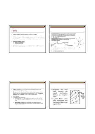
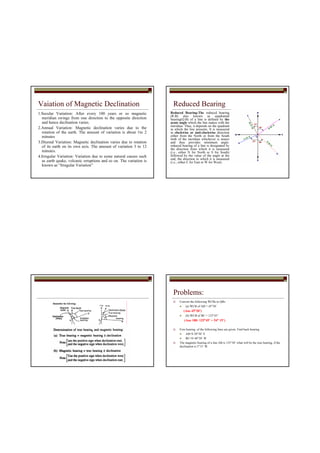
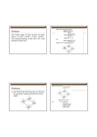
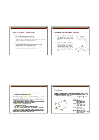
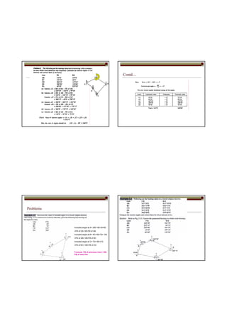
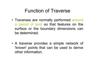
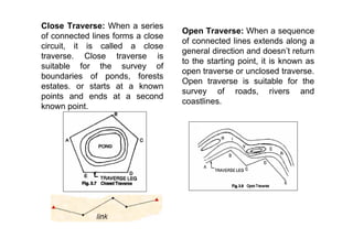
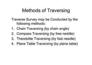
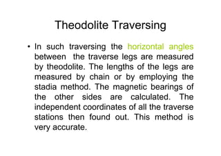
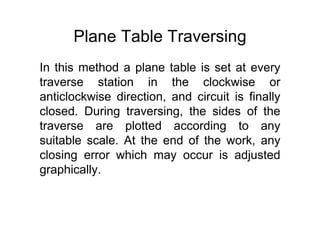
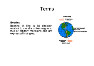
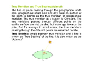
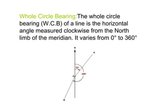
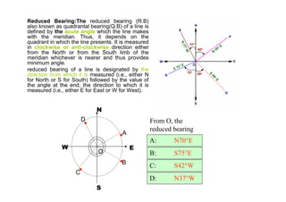
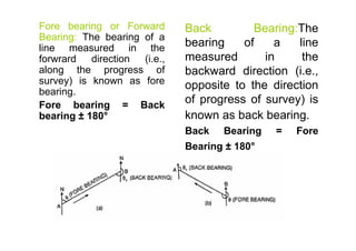
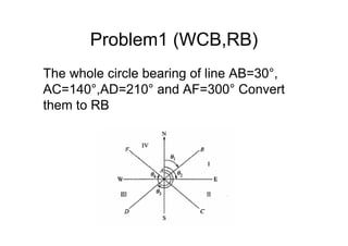
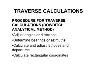
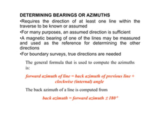
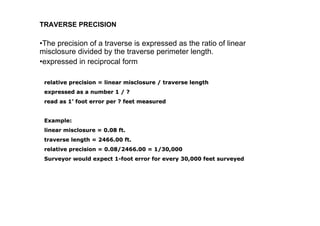
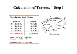
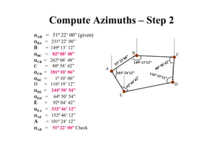
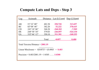
Traverse surveying involves using instruments to measure distance and direction to create a network of points. There are two main types of traverses - open and closed. Open traverses extend in one direction while closed traverses form a closed loop. Common surveying instruments and methods used in traverse surveying include chain, compass, theodolite, and plane table. Key terms in traverse surveying include bearings, meridians, and reductions of bearings. Traverse calculations involve adjusting angles or directions to ensure closure of the network of points. Sample problems are provided to demonstrate conversions between whole circle bearings, reduced bearings, and fore and back bearings.


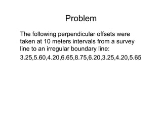
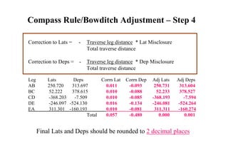
![Linear Misclosure/Closing Error
LinearLinear misclosuremisclosure = [(departure misclosure)= [(departure misclosure)22
+ (latitude misclosure)+ (latitude misclosure)2]1/22]1/2](https://image.slidesharecdn.com/1392741020traversesurvey-160502015525/85/1392741020-traverse-survey-40-320.jpg)
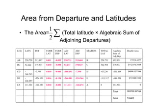
![Bowditch Graphical Method
For rough surveys or traverse of small area, adjustment can also be carried out
graphically. In this method of balancing, the locations and thus the coordinates
of the stations are adjusted directly. Thus, the amount of correction at any
station is proportional to its distance from the initial station .
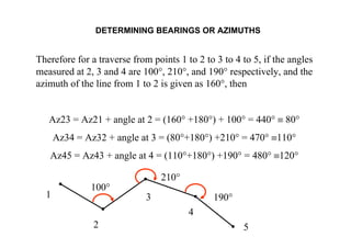
Let Po Qo Ro So To P' is the graphical plot of a closed-loop traverse PQRSTP.
The observed length and direction of traverse sides are such that it fails to get
balanced and is depicted in its graphical presentation by an amount Po P'.
Thus, the closing error of the traverse is Po P' (Figure 1). The error Po P' is to
be distributed to all the sides of the traverse in such a way that the traverse
gets closed i.e., P' gets coincides with Po in its plot. This is carried out by
shifting the positions of the station graphically. In order to obtain the length and
direction of shifting of the plotted position of stations, first a straight line is
required to be drawn, at some scale, representing the perimeter of the plotted
traverse. In this case, a horizontal line Po P' is drawn [Figure 3]. Mark the
traverse stations on this line such as Qo, Ro, So and To in such a way that
distance between them represent the length of the traverse sides at the chosen
scale. At the terminating end of the line i.e., at P', a line P' P a is drawn parallel
to the correction for closure and length equal to the amount of error as depicted
in the plot of traverse. Now, join Po to Pa and draw lines parallel to P' Pa at
points Qo, Ro, So and To. The length and direction of Qo Qa, Ro Ra, So Sa
and To Ta represent the length and direction of errors at Qo, Ro, So and To
respectively. So, shifting equal to Qo Qa , Ro Ra, So Sa and To Ta and in the
same direction are applied as correction to the positions of stations Qo, Ro, So
and To respectively. These shifting provide the corrected positions of the
stations as to Qa, Ra, Sa,Ta and Pa. Joining these corrected positions of the
stations provide the adjusted traverse Pa Qa Ra, Sa Ta [Figure 2].](https://image.slidesharecdn.com/1392741020traversesurvey-160502015525/85/1392741020-traverse-survey-47-320.jpg)
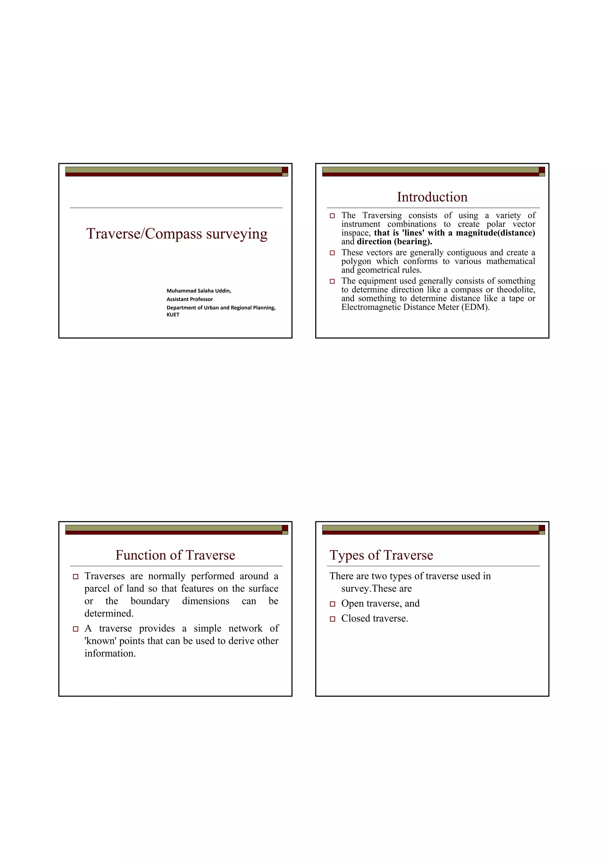
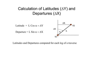
![Mid-Ordinate Rule
Area = ([O1+O2+O3+ .....+ On]*L)/n
(O1 +O2 + O3 + .....+ On)*d
Where:
L = length of baseline
n = number of equal parts, the baseline is divided
d = common distance between the ordinates](https://image.slidesharecdn.com/1392741020traversesurvey-160502015525/85/1392741020-traverse-survey-51-320.jpg)
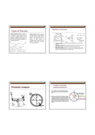
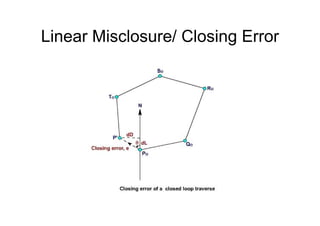
![Average Ordinate Rule
Area = [(O1+ O2+ O3+ .... + On)*L]/(n+1)
• L = length of baseline
• n = number of equal parts (the baseline divided)
• d = common distance](https://image.slidesharecdn.com/1392741020traversesurvey-160502015525/85/1392741020-traverse-survey-52-320.jpg)
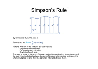
![Trapezoidal Rule
• Area = [(O1+ On)/2+ O2+ .... + On-1]*d](https://image.slidesharecdn.com/1392741020traversesurvey-160502015525/85/1392741020-traverse-survey-53-320.jpg)