Download as PDF, PPTX
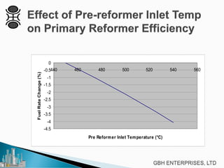
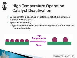
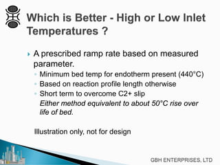


This document discusses operating pre-reformers at high temperatures and the associated benefits and drawbacks. It notes that while higher temperatures allow for better thermal efficiency and feedstock flexibility in reformers, they can also cause hydrothermal sintering of catalysts over time from high heat and steam. The document provides guidelines for startup, reduction, and operation of pre-reformer catalysts to maximize performance while mitigating sintering risks.


![5G Explained! A High Level Overview [Introduction]](https://cdn.slidesharecdn.com/ss_thumbnails/5gexplainedahighleveloverview-260119165306-cc137a3e-thumbnail.jpg?width=640&height=640&fit=bounds)


