Downloaded 1,741 times
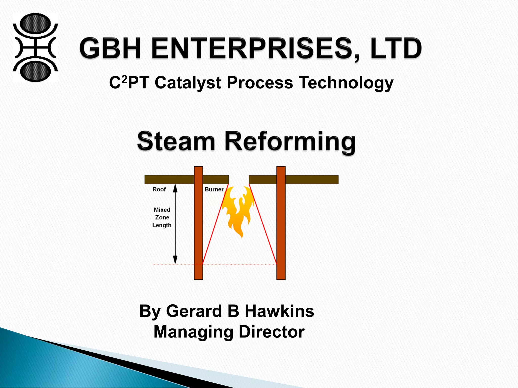
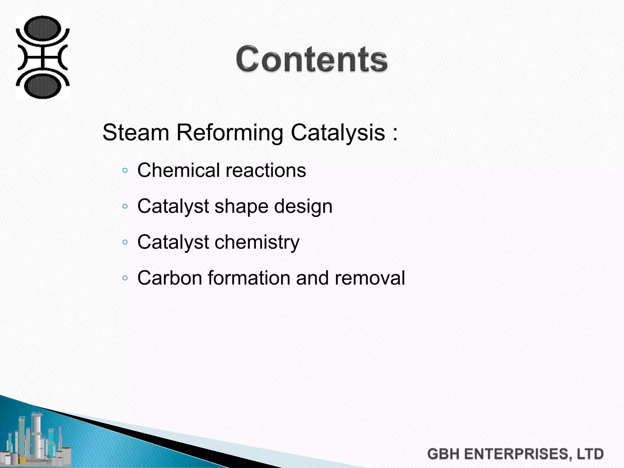
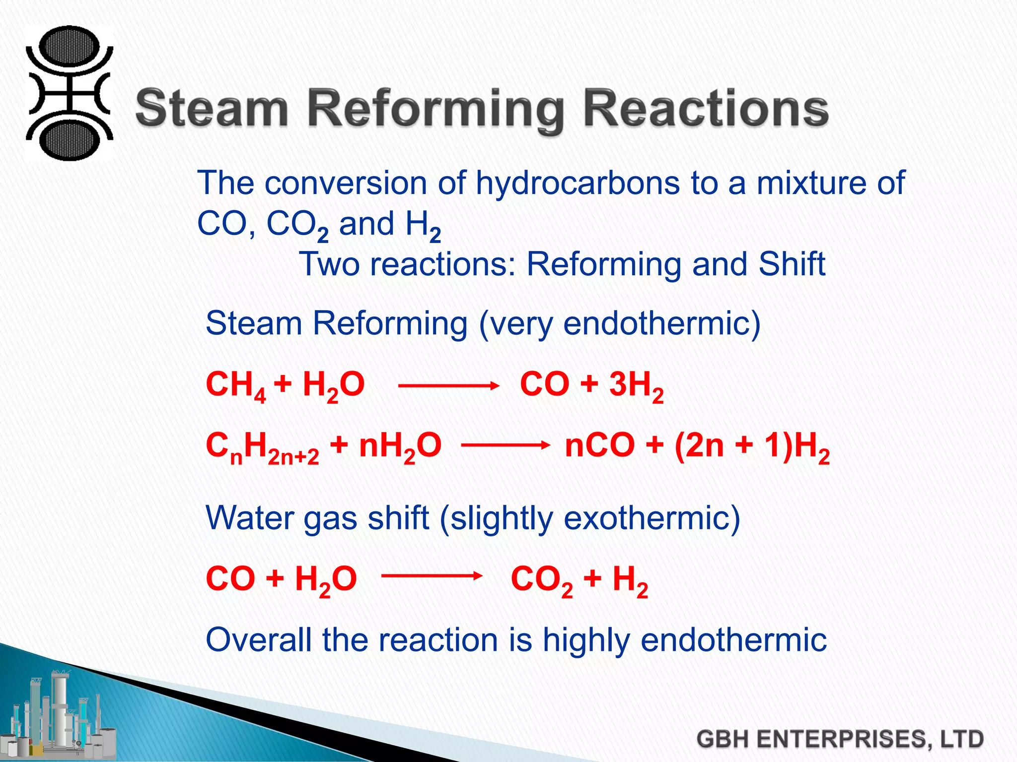
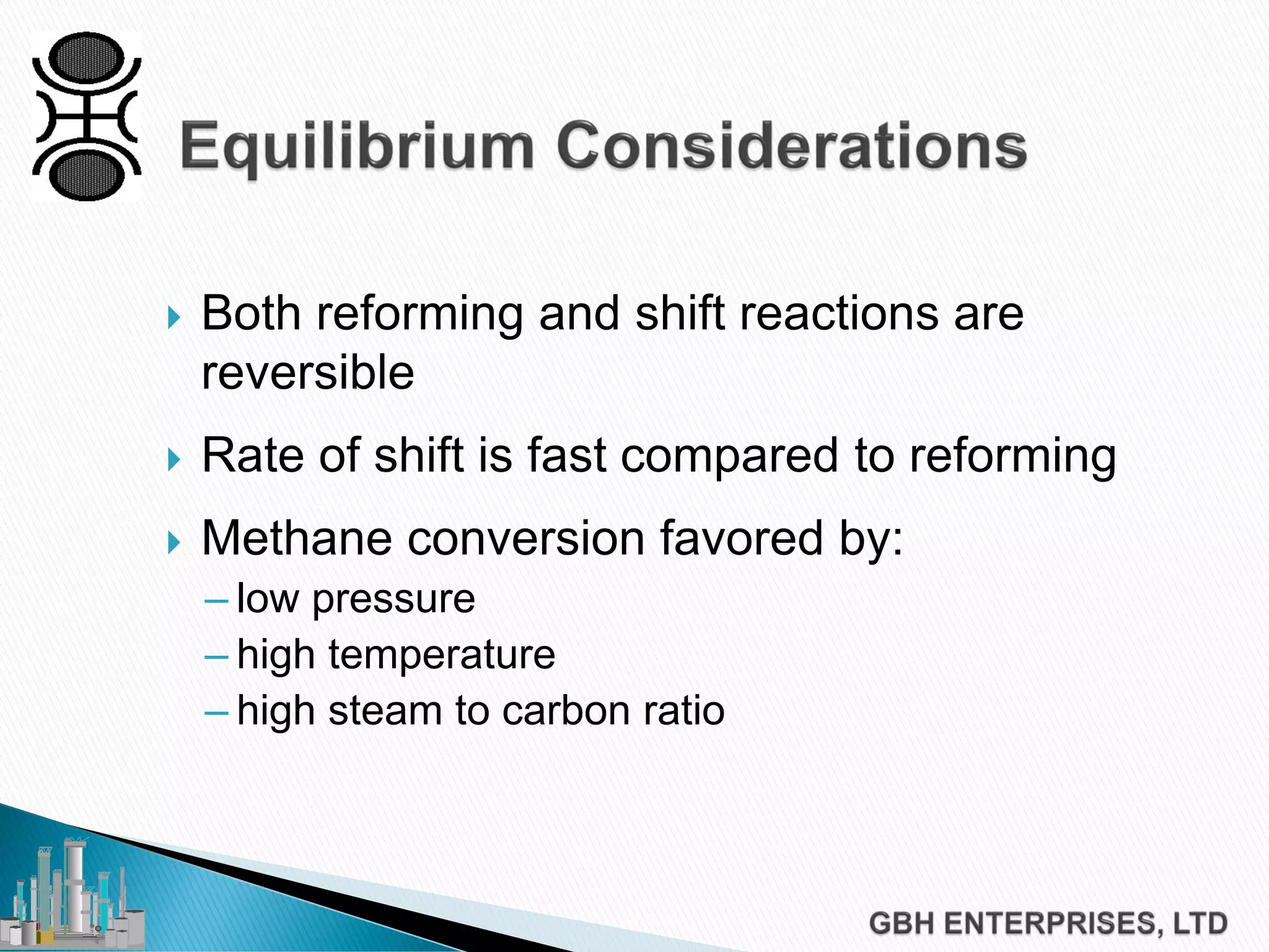
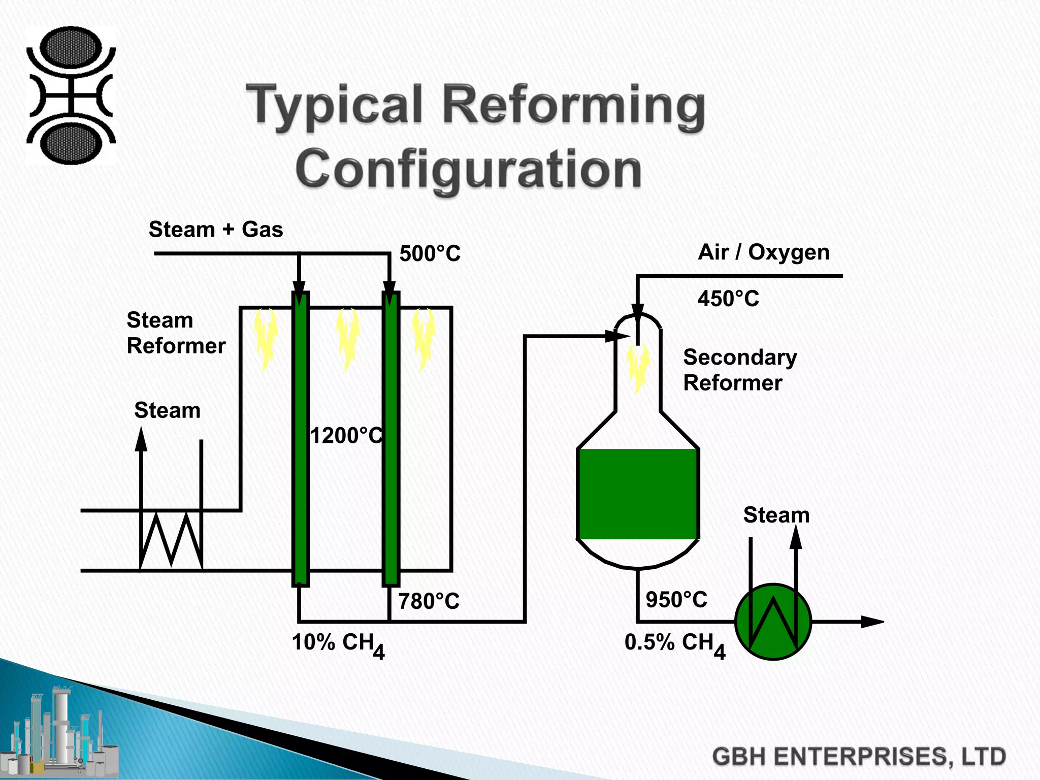
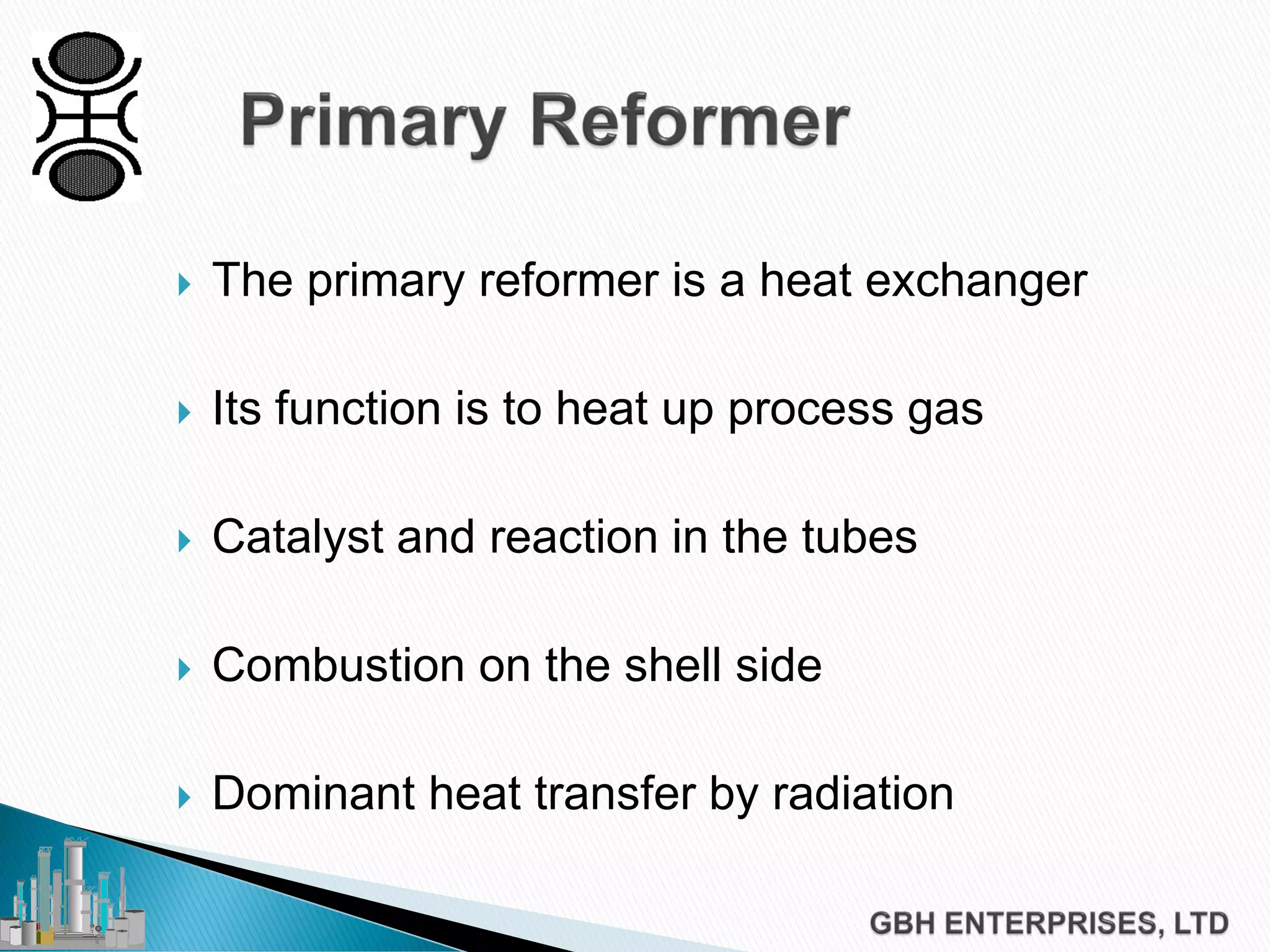
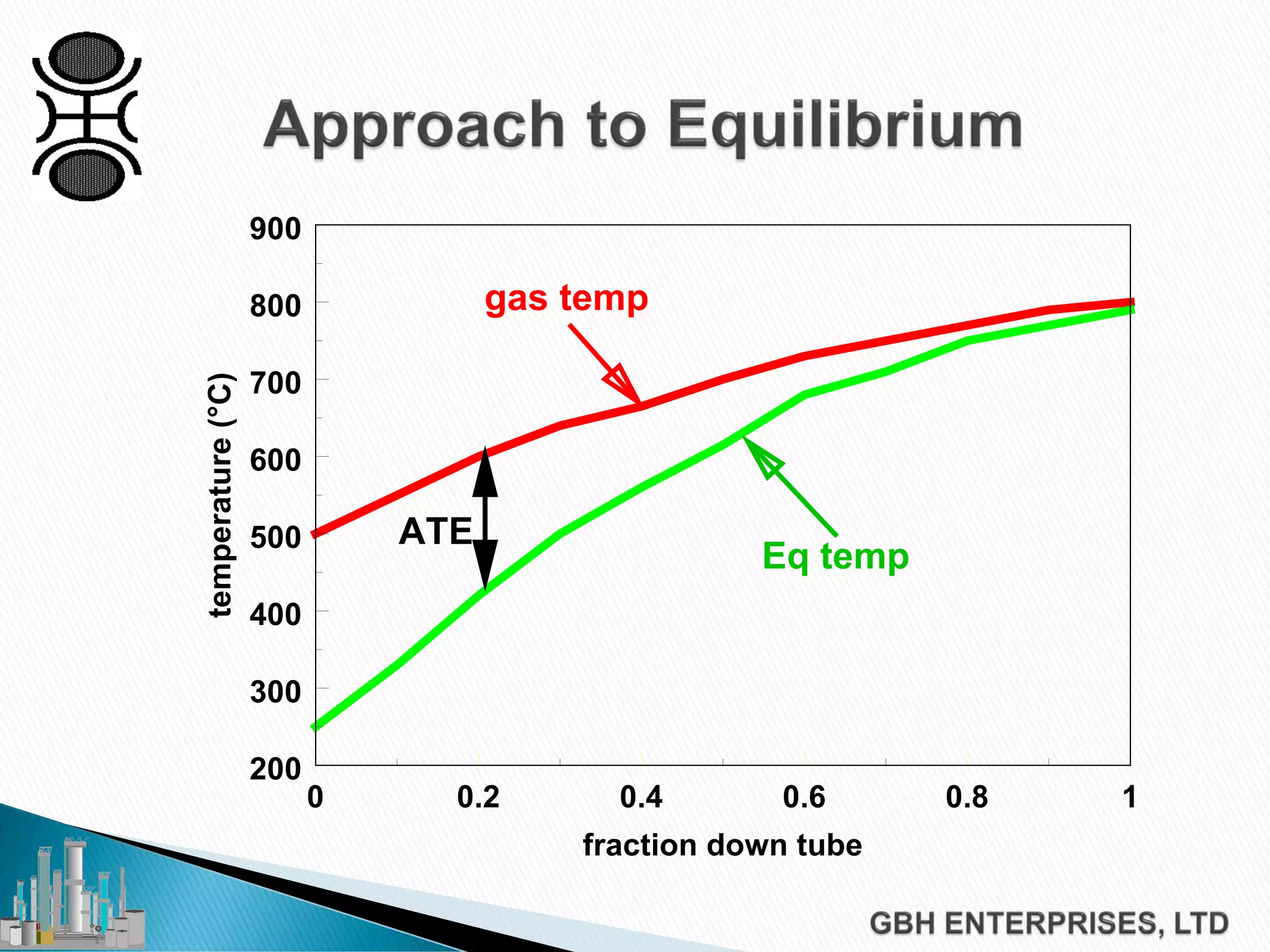
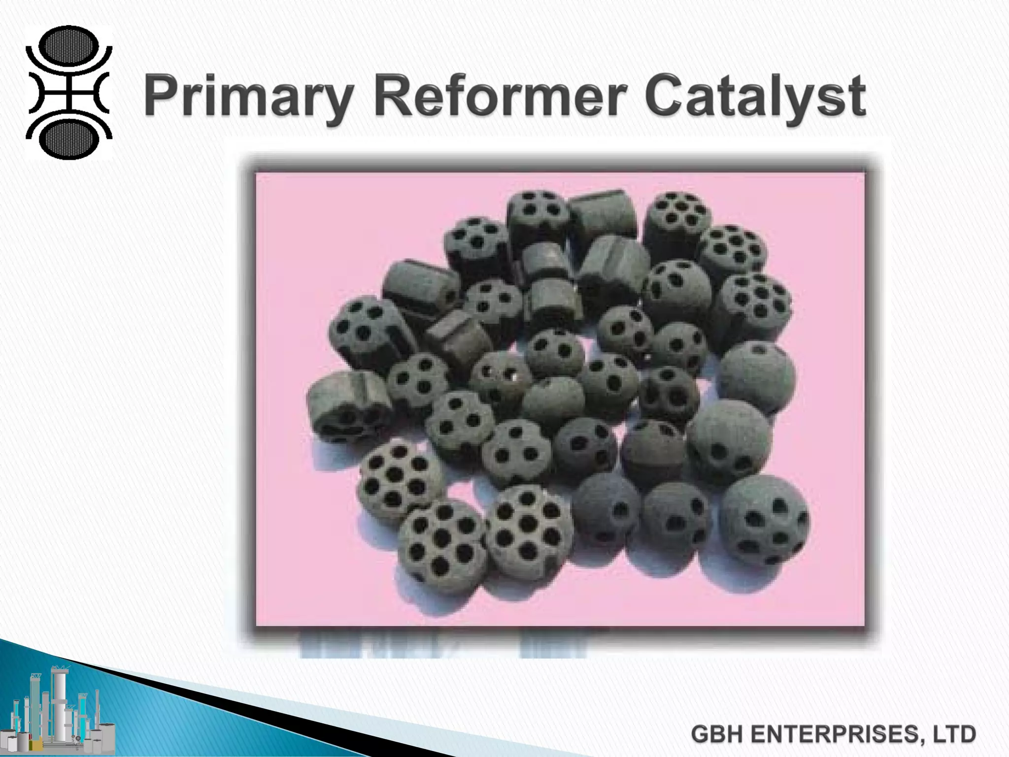
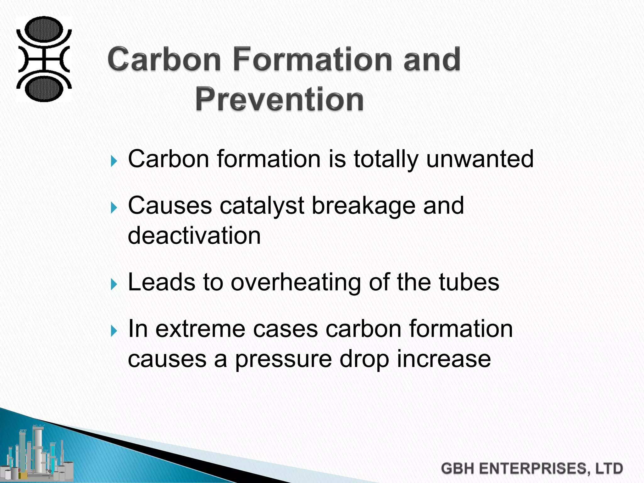
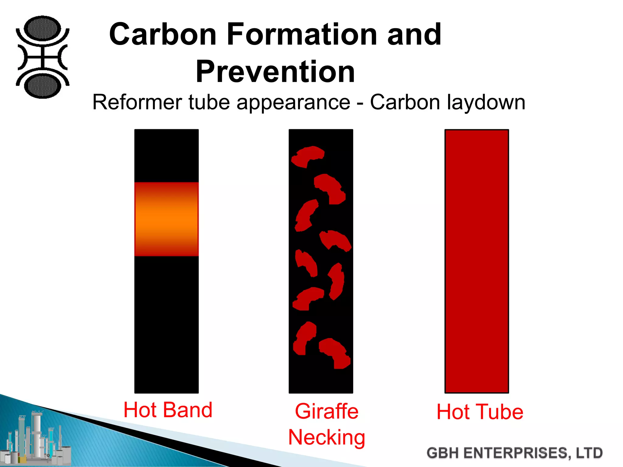
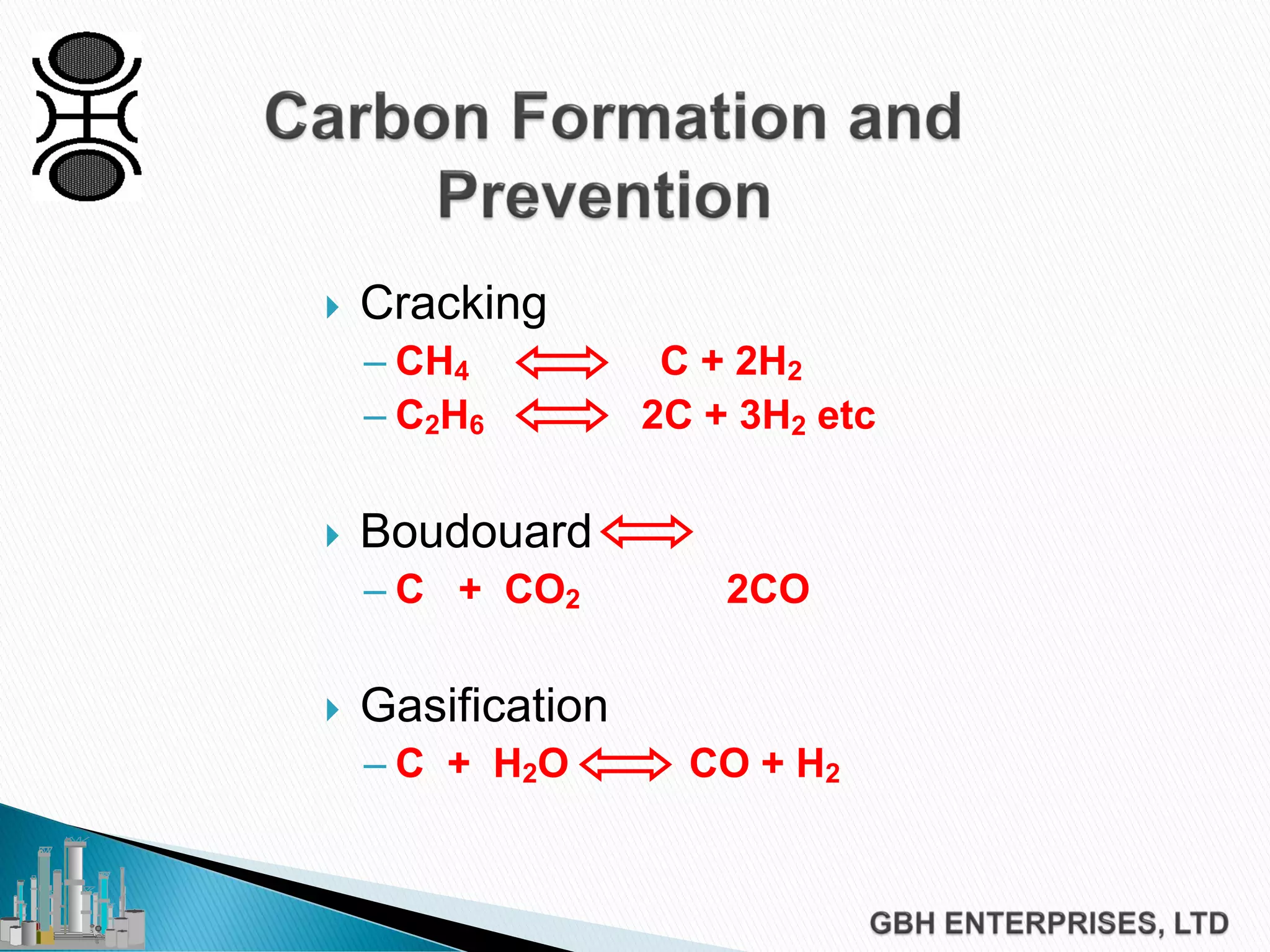
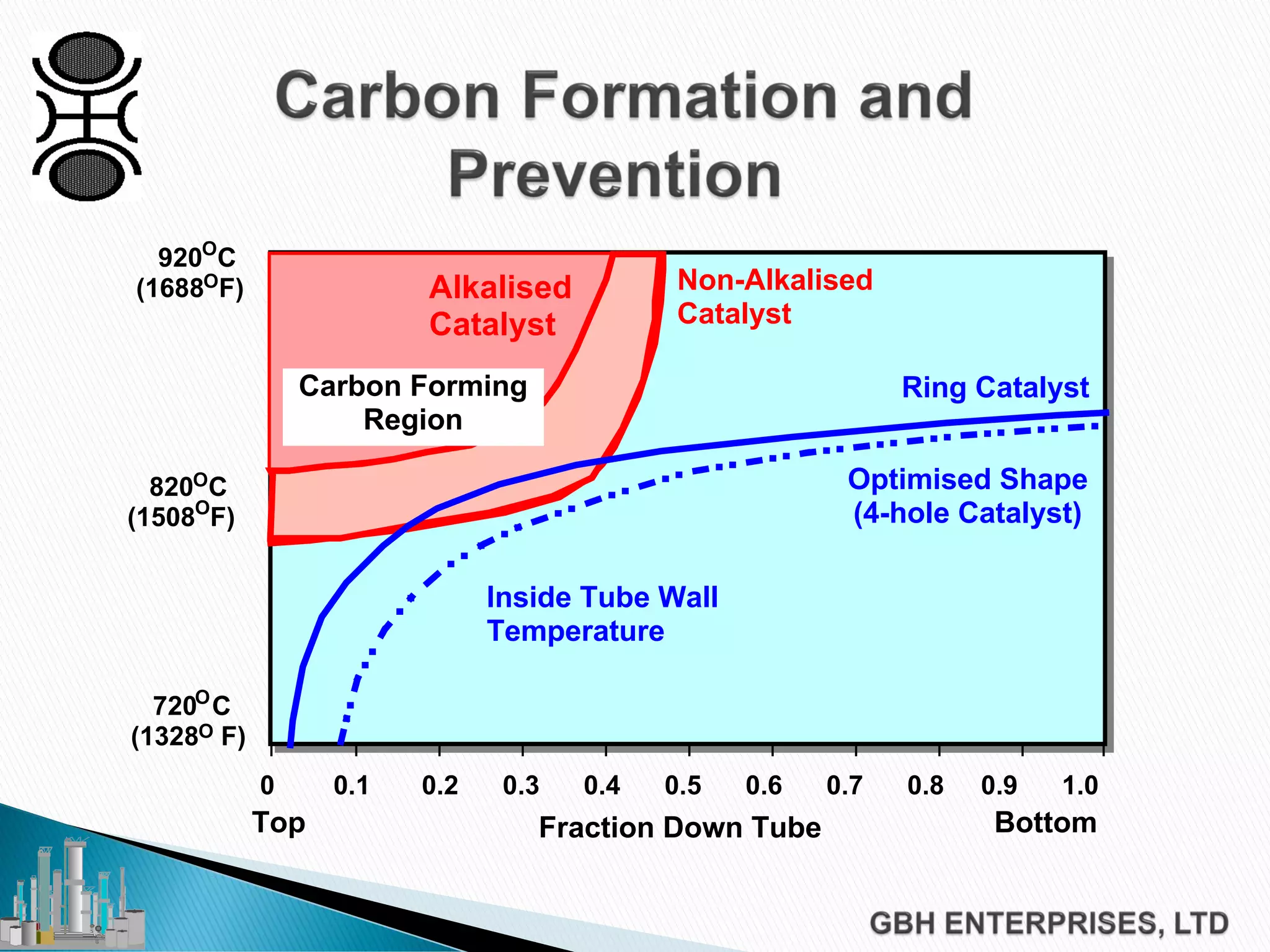
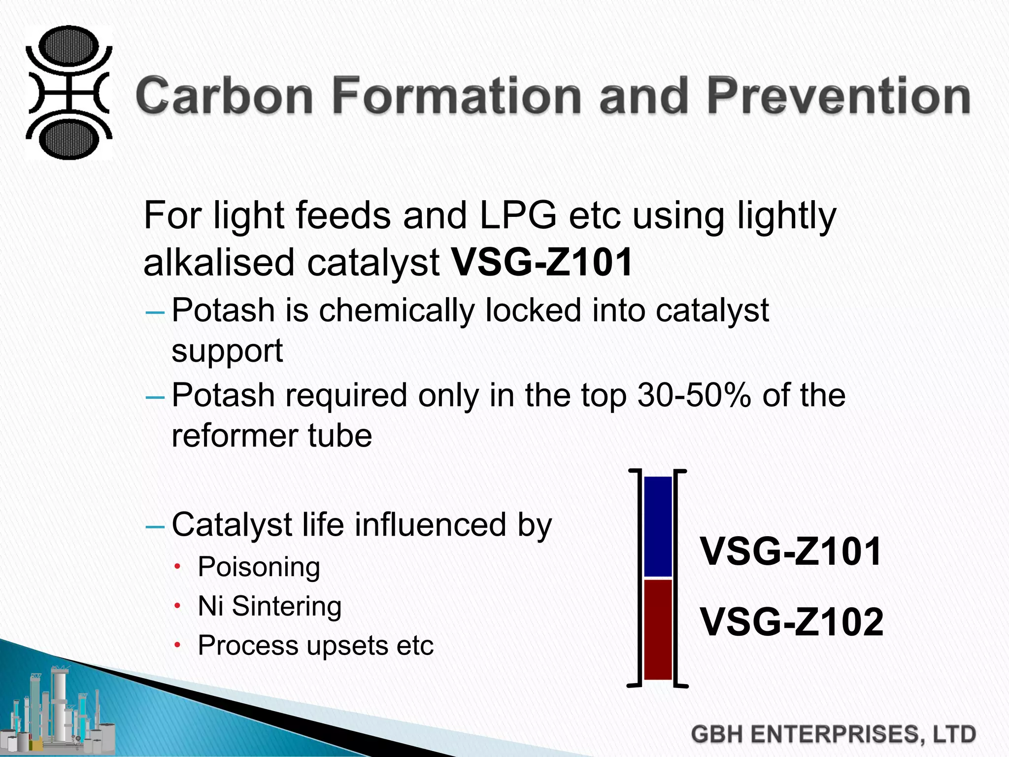

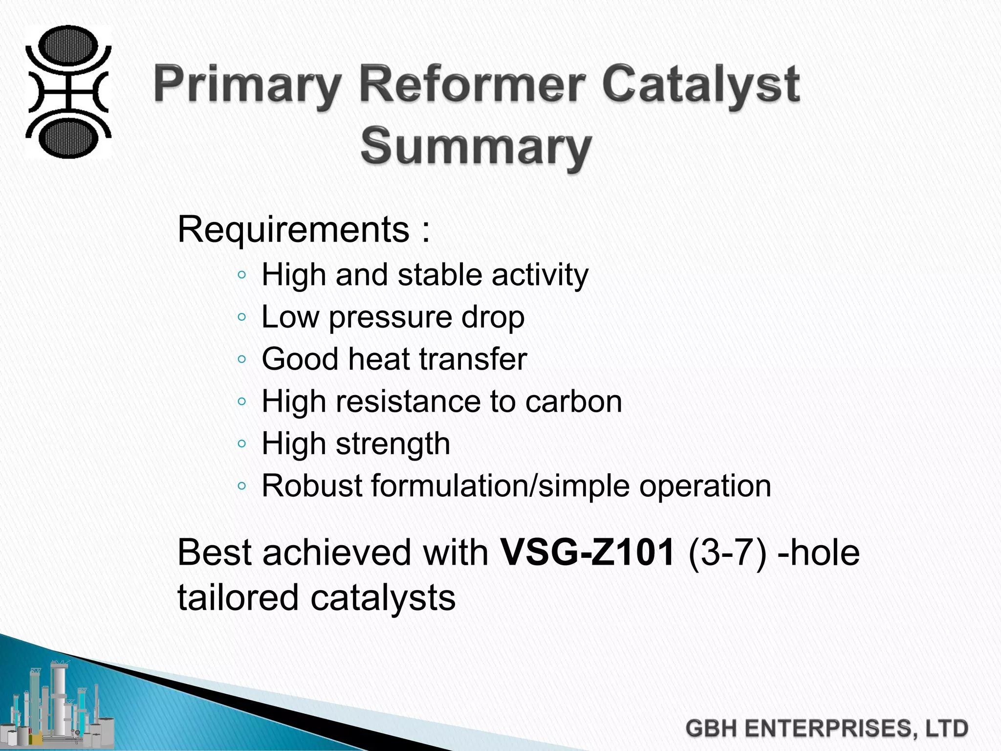


This document discusses catalyst process technology for steam reforming of hydrocarbons. It covers the chemical reactions involved, catalyst design considerations like shape and chemistry, and carbon formation and removal. Key points discussed include the conversion of hydrocarbons to syngas, reforming and shift reactions, factors that influence methane conversion, reformer design, optimizing catalyst shape for heat transfer and pressure drop, using alkali-doped catalysts to prevent carbon formation, and tailored catalyst requirements.


![Coded Agents – with UiPath SDK + LangGraph [Virtual Hands-on Workshop]](https://cdn.slidesharecdn.com/ss_thumbnails/codedagentsdeck-251215155422-5497c599-thumbnail.jpg?width=640&height=640&fit=bounds)


