Downloaded 73 times

![ANNUAL TURNAROUND JUNE 2015 Page | 5
DETAILED REPORT
After planned ammonia plant shutdown, reformer cooling using inert gas (Nitrogen)
was prolonged for LTCO convertor bed cooling (@1000 hours on 10th June, 2015).
Depressurization of front end was done at HT guard inlet vent point after isolating HTCO
convertor inlet isolation valve. After depressurizing, following jobs were done in the
mentioned order (Jobs completed in approximately 8 hours)-
Reformer feed spaded (FRRC-203 d/s)
Make gas boiler(H201) outlet spaded
Reformer furnace man way covers opened
Reformer outlet T-plug removed
All reformer burner guns removed
Demineralized water flushing done for fuel naphtha header towards raw naphtha
storage tank
Reformer fuel naphtha strainer spaded (SM1 u/s)
Reformer tube counter weight locked
Reformer tube and pigtail flanges insulation removed
All 224 tube flanges bolt removal initiated. Long pigtail to short pigtail flange
removed and respective orifices positions were marked and tied to the same flanges (Jobs
completed in approximately 24 hours).
Unloading of primary reformer was started at 1825 hours on 10th June, 2015. CR-
Asia BIVAC with a single hose was used for unloading with vacuum reading of -350 mm
Hg/-0.135 inch Hg. Dust sample was collected from bottom T- plug and handed over to Q/C
& Lab for analyzing. With completion of catalyst unloading for “A” & “B” row, rigs for
measuring differential pressure across tubes were being made ready for MCFL rig. [Note: A
second vacuum hose was made ready and utilized to accelerate the catalyst unloading
process. A metal tip nozzle was being used in case of compacted spent catalyst unloading. A
mark with tape was made on each hose being inserted into tubes to make sure the catalyst
support grid was not being damaged for every tube.]](https://image.slidesharecdn.com/report-150717142416-lva1-app6891/85/Reformer-Catalyst-Report-5-320.jpg)
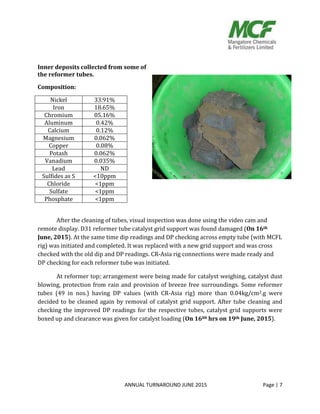
![ANNUAL TURNAROUND JUNE 2015 Page | 6
Spent catalyst sampling was done for the following tubes A24, A44, A48, B16 and
D16. As decided, samples were collected at heights of 3m, 6m and 9m for all the 5 tubes.
Reformer catalyst unloading for all 224 tubes was completed on 12th June, 2015 (Job
completed in approximately 48 hours). The spent catalyst was being collected in the
provided Mangala Urea bags and shifted to the reformer bottom shed. All 224 tubes empty
dip readings were noted down. Later that night at 2230 hours, all reformer tubes inner
surface cleaning by stainless steel wire mesh was initiated. To extract the excess scale
formation inside the reformer tubes, arrangement was made with a buffing plate (Diameter
100mm) having connected rods (threaded with nut and bolt) for extension as the plate
moves inside the tube. As the assembly was not much efficient and the potential risk of it
getting clogged was more, the arrangement was rejected.
Simultaneously bottom layer Ni catalyst drums were being shifted from the storage
area to shed (reformer bottom area) and top layer NiK catalyst to shed (stores area). [Note:
Catalyst drums were being shifted in absence of rain. Drum rolling to be avoided. Keep the
drums on wooden pallets, avoid stacking them up. Protect from rain and stagnant water by
providing tarpaulin cover. Keep the lids on, avoid catalyst exposure and do not damage the
drums.]
DP measurement details:
CR-ASIA DP apparatus orifice diameter: 8mm.
MCF DP rig orifice downstream hose length/diameter: 6.00mts/ 0.75”.
Orifice u/s instrument air maintained pressure: 4.00 kg/cm2. (Transmitter range: 0-10
kg/cm2.g).
Orifice d/s pressure indicates DP. (Transmitter range: 0-4 kg/cm2.g).](https://image.slidesharecdn.com/report-150717142416-lva1-app6891/85/Reformer-Catalyst-Report-6-320.jpg)
![ANNUAL TURNAROUND JUNE 2015 Page | 8
Test loading of first layer (Ni) catalyst was done for the first tube of each row i.e. A1,
B1, C1 and D1 in presence of Sud Chemie representative. Dip and DP readings were noted
down as a reference value for rest of the tubes. It was decided to go ahead with 5 buckets of
catalyst for each tube weighing 7kgs. Supervision was deputed to employees to follow up
the catalyst weighing, catalyst drum being utilized and correctional weight for each tube.
[Note- Weighing machine was deployed from ABC plant to weigh catalyst for loading.
Instrument air connection was provided from PICV-2211 tapping for checking reformer tube
DP and catalyst dust blowing. A separate instrument air connection was provided from F-
4210 area for air wench to lift catalyst drums.]
As catalyst available was close to the amount needed after loading “A” and “B” row
tubes, it was decided to load remaining tubes with maximum of 36kgs till all tubes are
covered. Dip readings were noted of all reformer tubes filled with Ni catalyst. Later dip
corrections were done by additional top up for selective tubes to get the dip reading closer
to 7.2m (Completed by 0700hrs on 21st June, 2015). DP readings for all tubes with Ni
catalyst were noted down with CR-Asia rig and later with MCFL rig. As for the Ni catalyst
loading, all new catalyst was utilized and 1 drum old catalyst weighing 112.8kg/141liters
was unutilized which was shifted to DAP plant storage.
After getting approval of DP and dip readings, clearance was given for loading of
second layer (NiK) catalyst. Test loading was done for first tube of each row i.e. A1, B1, C1
and D1. Dip and DP readings were noted down as a reference value for the rest of the tubes.
It was decided to go ahead with 7 buckets for each tube weighing 10kgs. After loading of
NiK catalyst for all tubes, dip readings were noted down and correction were done by
additional top up for selective tubes to get the dip reading closer to 0.8m (Completed by
0600hrs on 23rd June, 2015). DP readings for NiK catalyst were noted down using CR-Asia
and later with MCFL rig. DP correction was done for B1 and B49 tubes as the respective DP
readings were on the lower side. For NiK catalyst, 3 full drums of catalyst and a partly filled
drum was shifted to catalyst storage (725 liters in total).](https://image.slidesharecdn.com/report-150717142416-lva1-app6891/85/Reformer-Catalyst-Report-8-320.jpg)

This document summarizes the annual catalyst unloading and reloading process for the primary reformer at a chemical plant. It describes removing the spent catalyst from 224 tubes using vacuum pumps over 48 hours. Samples were taken and tubes were cleaned. New catalyst was then loaded in two layers - a bottom layer of nickel catalyst in 5 buckets per tube and a top layer of nickel-potassium catalyst in 7 buckets per tube. Dip heights and pressure drops were measured to ensure proper loading. The process was completed over 11 days during the annual turnaround.