Downloaded 239 times

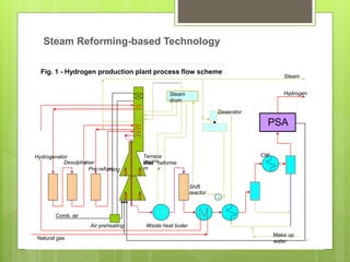
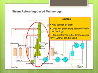
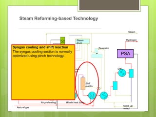
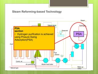
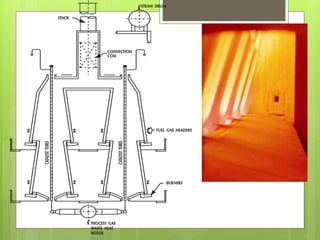


Steam reforming is a common method for producing hydrogen in refineries. It involves reacting light hydrocarbons like methane with steam over a nickel catalyst at high temperatures. The Terrace Wall Steam Reformer is a compact design that uses inclined terraces on both sides of catalyst tubes to provide uniform heating. This leads to lower costs and allows natural draft operation while maintaining full hydrogen production.


