Downloaded 814 times


![Ion Exchange to Generate Acid
Sites (H+)
Na+-Z- + NH4
+ Na+ + NH4
+-Z-
NH4
+-Z- H+-Z- + NH3
↑
calcine
3Na+-Z- + RE(H2O)6
3+ 3Na+ + RE(H2O)6
3+-[Z]3
-
RE(H2O)6
3+-[Z]3
- RE(H2O)5(OH)2+ -H+-[Z]3
-
hydrolysis
Ammonium Exchange
Rare Earth Exchange
www.gbhenterprises.com](https://image.slidesharecdn.com/fcccatalystdesignmorphphysiooptimization-150107212315-conversion-gate01/75/FCC-Catalyst-Design-Morphology-Physiology-Reaction-Chemistry-and-Manufacturing-16-2048.jpg)

![Unit-Cell Size and Si/Al ratio
Numerous relationships given in the literature
Breck and Flanigen relationship widely used
NAl / ucs = 115.2 [ ao - 24.191 ]
and: NSi / ucs = 192 - NAl / ucs
thus: Si / Alframework = NSi / NAl
www.gbhenterprises.com](https://image.slidesharecdn.com/fcccatalystdesignmorphphysiooptimization-150107212315-conversion-gate01/75/FCC-Catalyst-Design-Morphology-Physiology-Reaction-Chemistry-and-Manufacturing-18-2048.jpg)


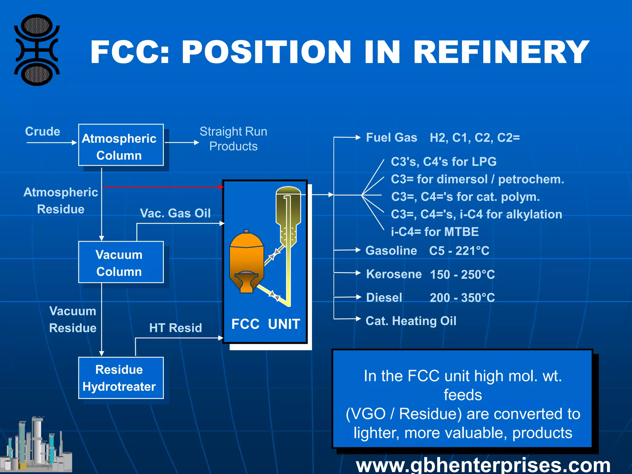
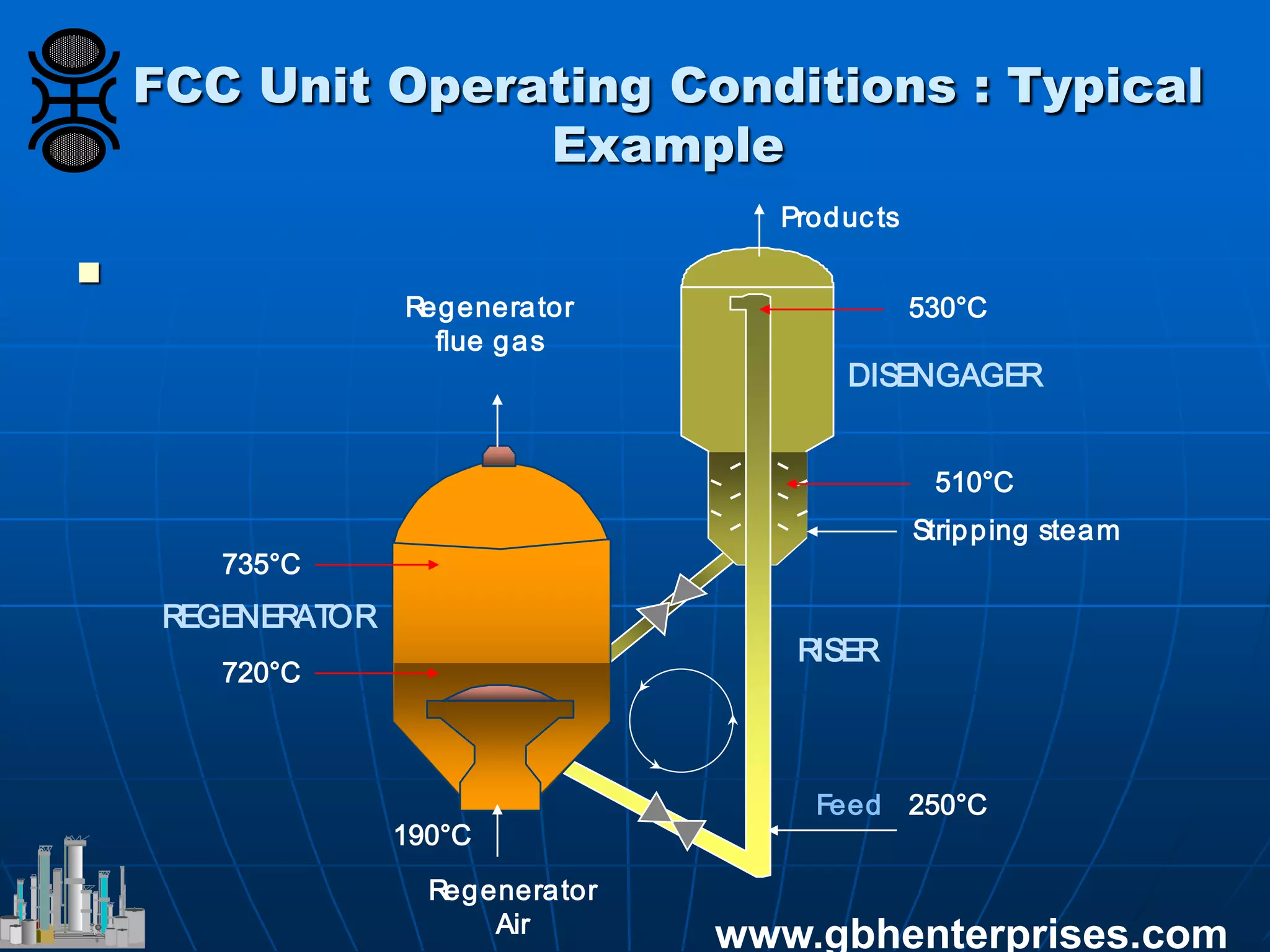
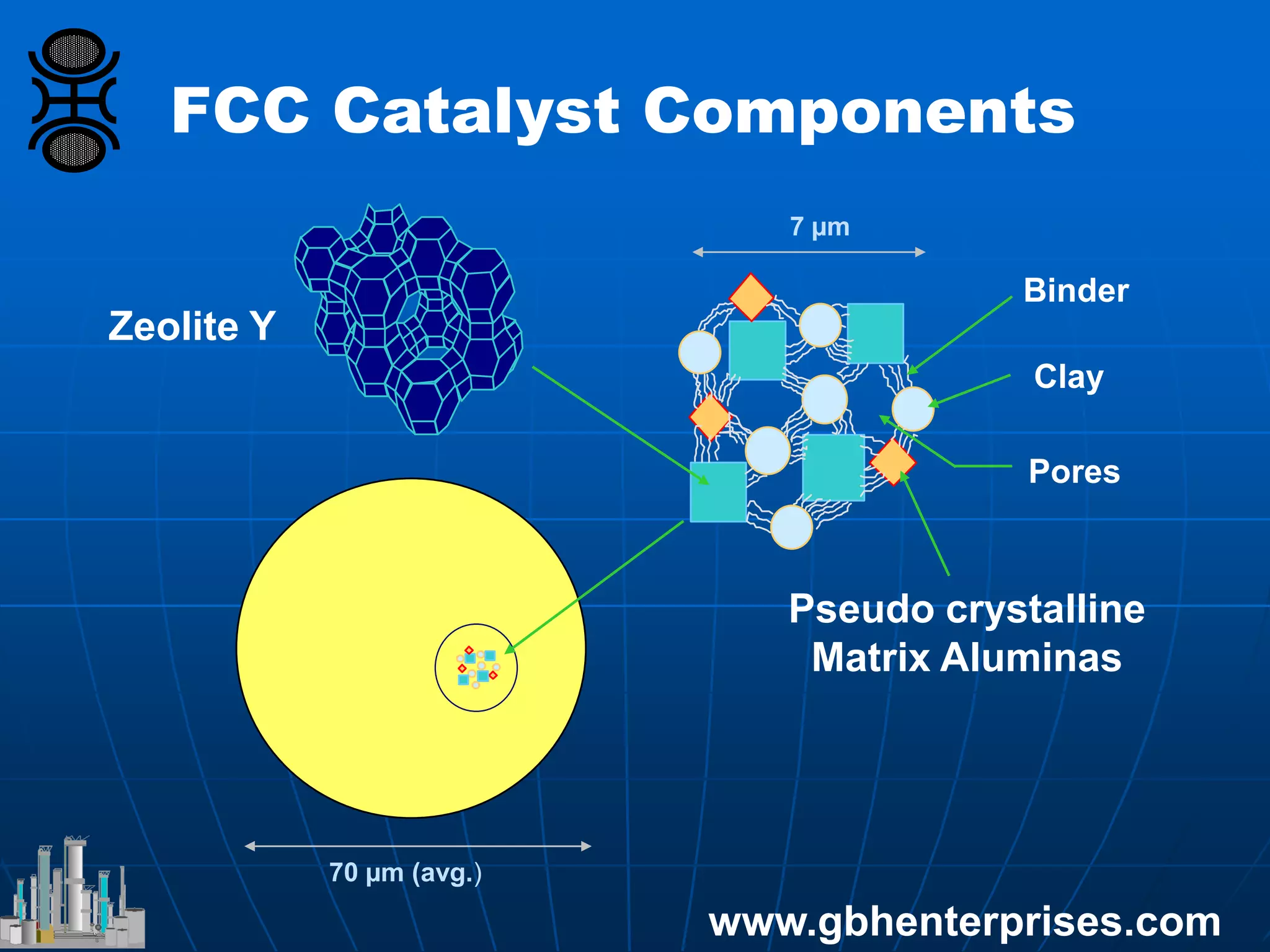
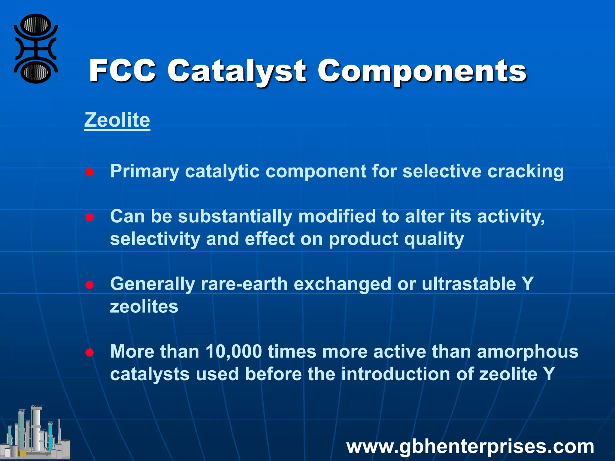
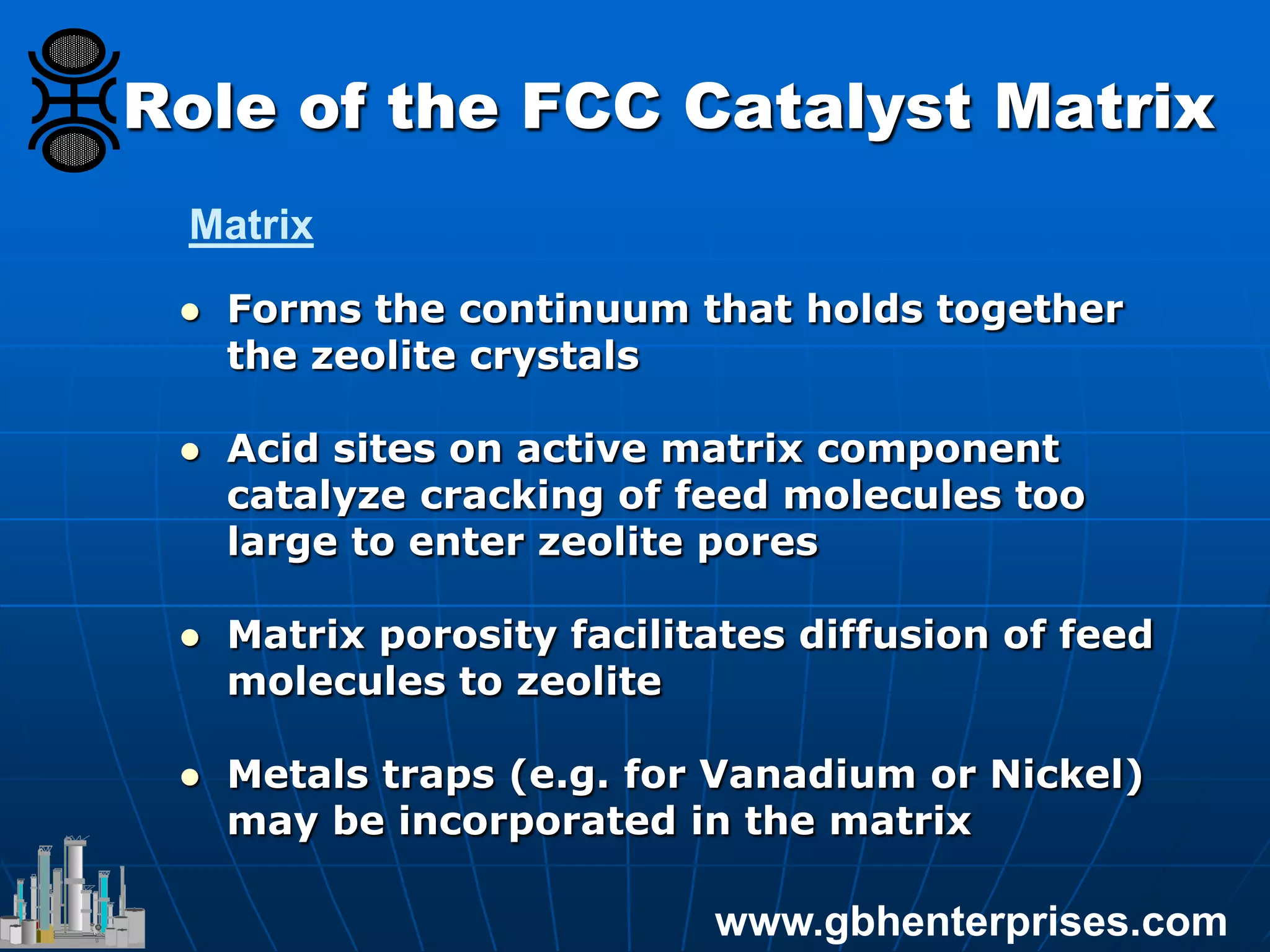
The document provides an in-depth overview of FCC catalyst design, including components such as zeolites and matrices, their manufacturing processes, and reaction chemistry involved in converting high molecular weight feeds into lighter hydrocarbons. It discusses the operational conditions of an FCC unit, the roles of various catalyst components, and the effects of zeolite properties on product selectivity and cracking activity. Additionally, the document covers the environmental implications of FCC processes, including sulfur management and NOx emissions reduction strategies.