Download as PDF, PPTX


The document outlines the principles and benefits of pre-reforming technology in hydrogen production, including its effects on primary reformers, catalyst management, and feedstock specifications. It highlights various markets such as town gas, hydrogen, methanol, ammonia, and GTL, along with advantages like fuel savings, increased efficiency, and adaptability to feedstock changes. Additionally, it emphasizes the importance of systematic data analysis, temperature profiles, and effective catalyst management for optimizing pre-reformer performance.
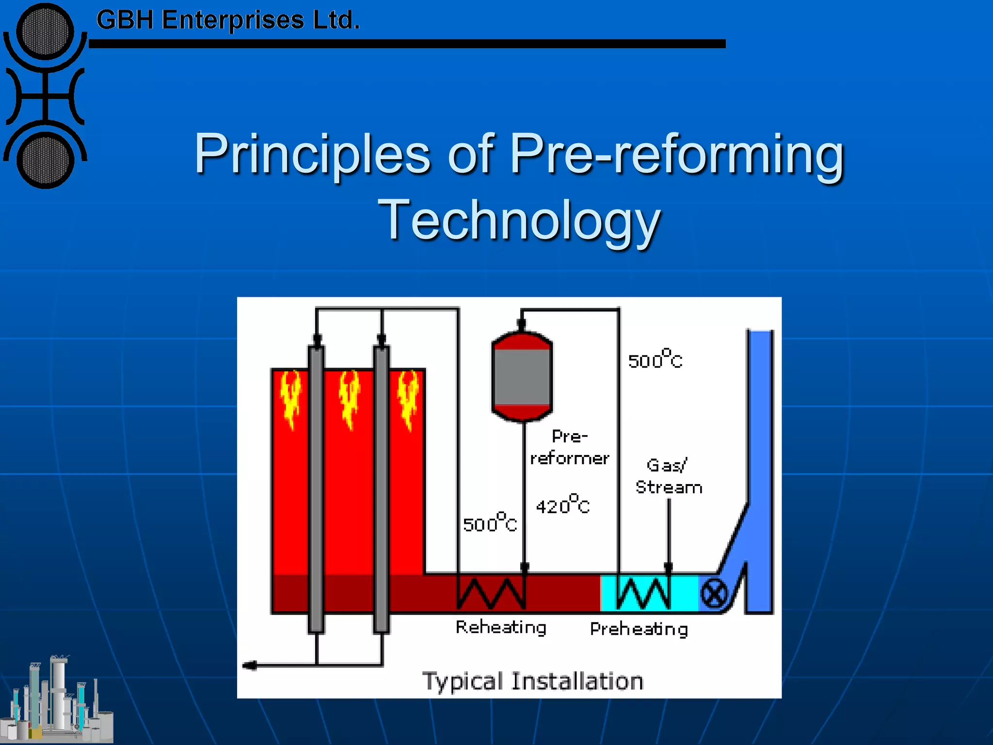
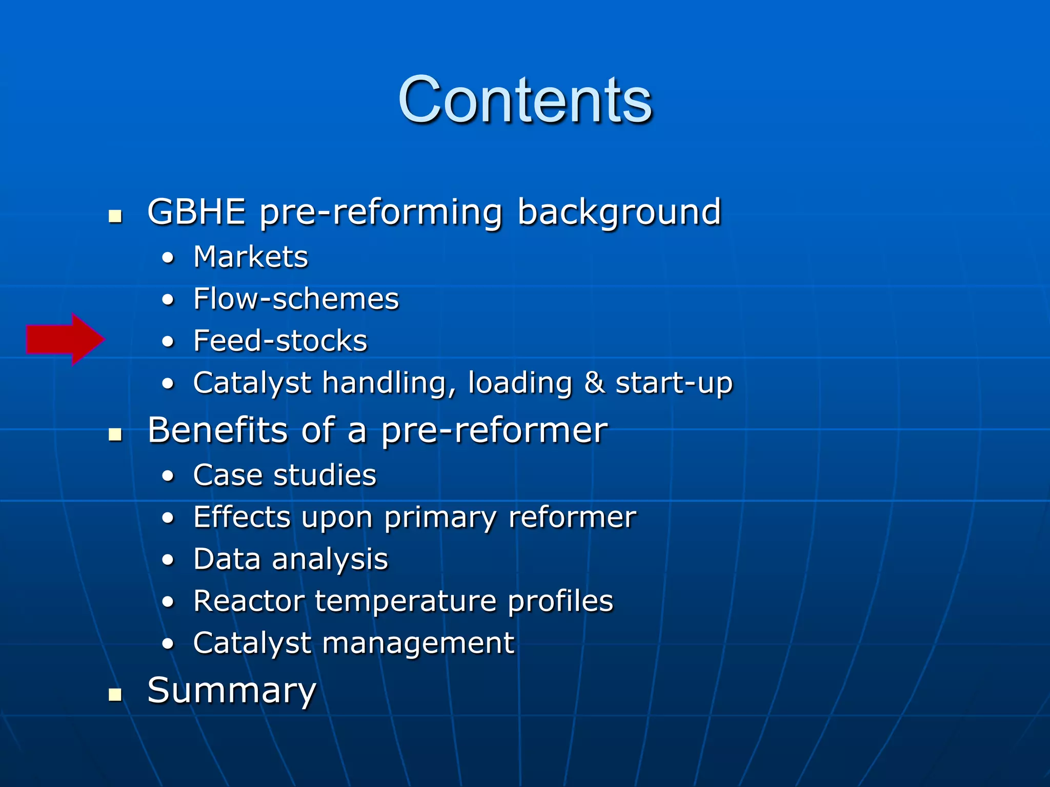
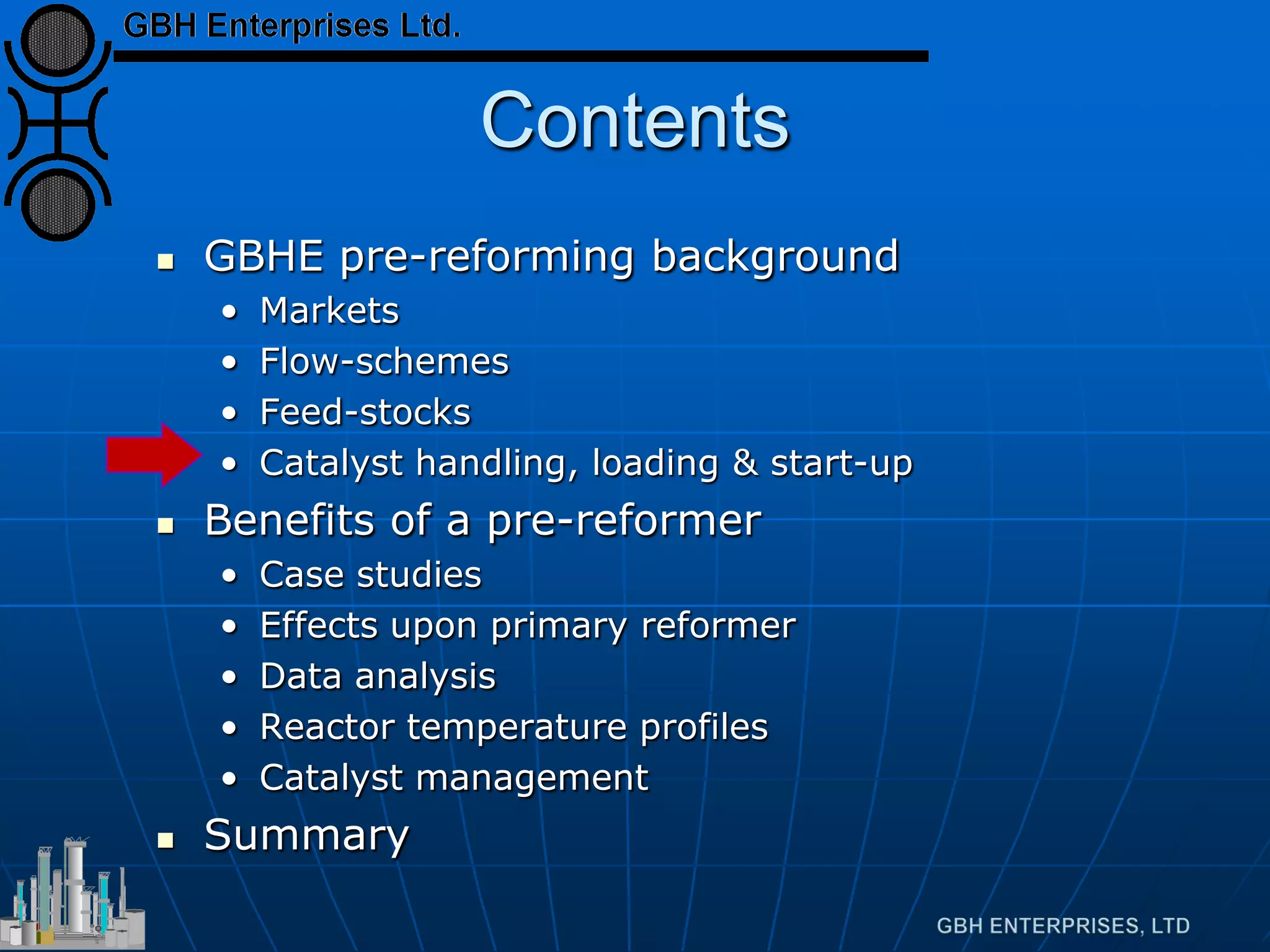
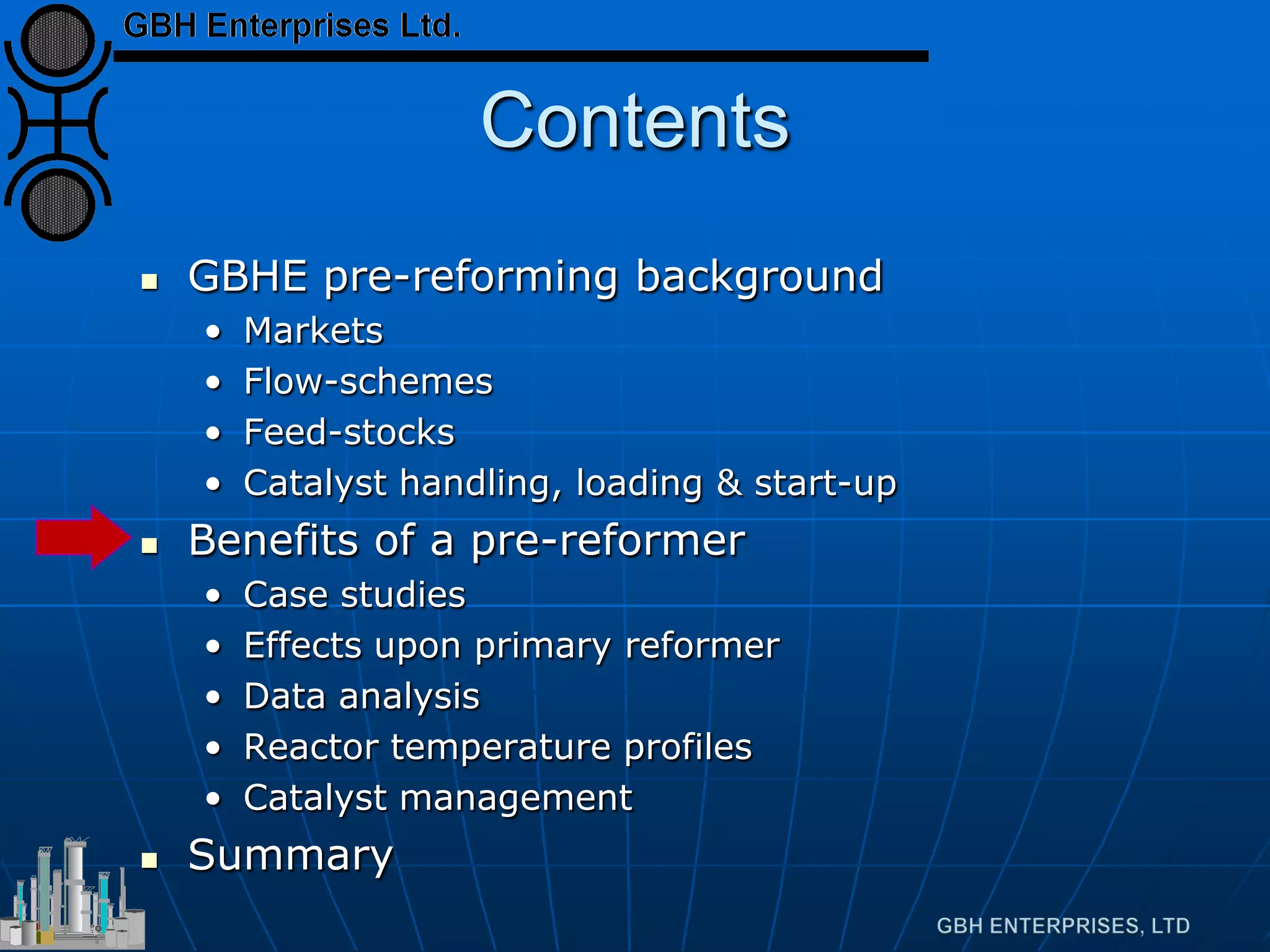
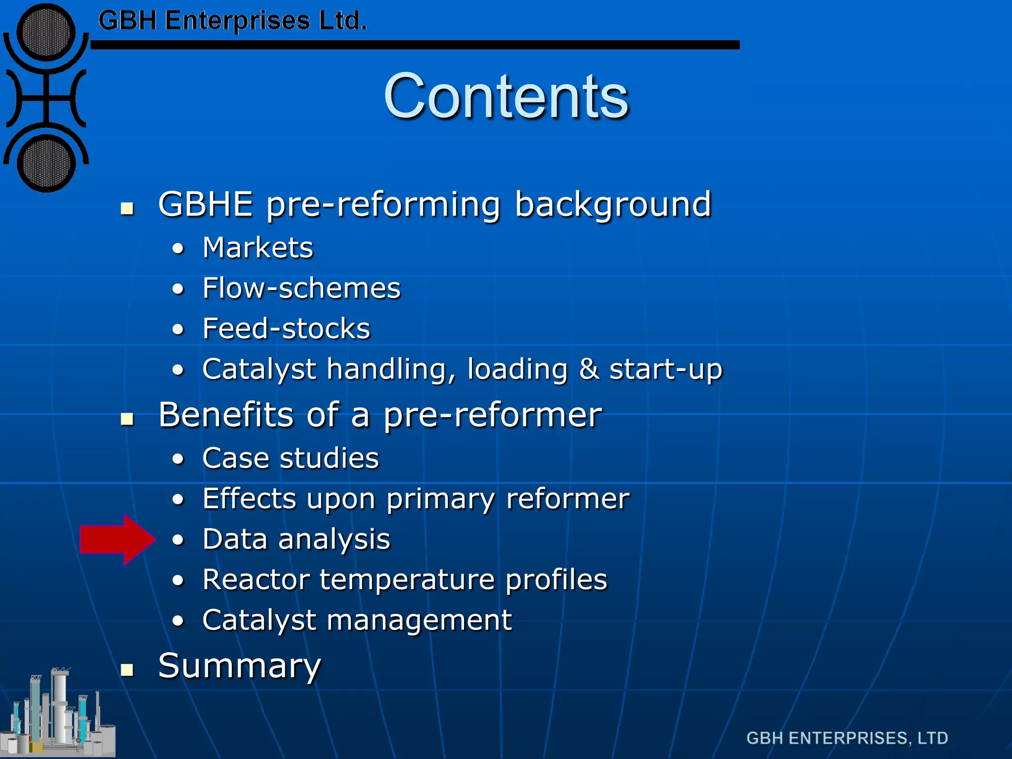
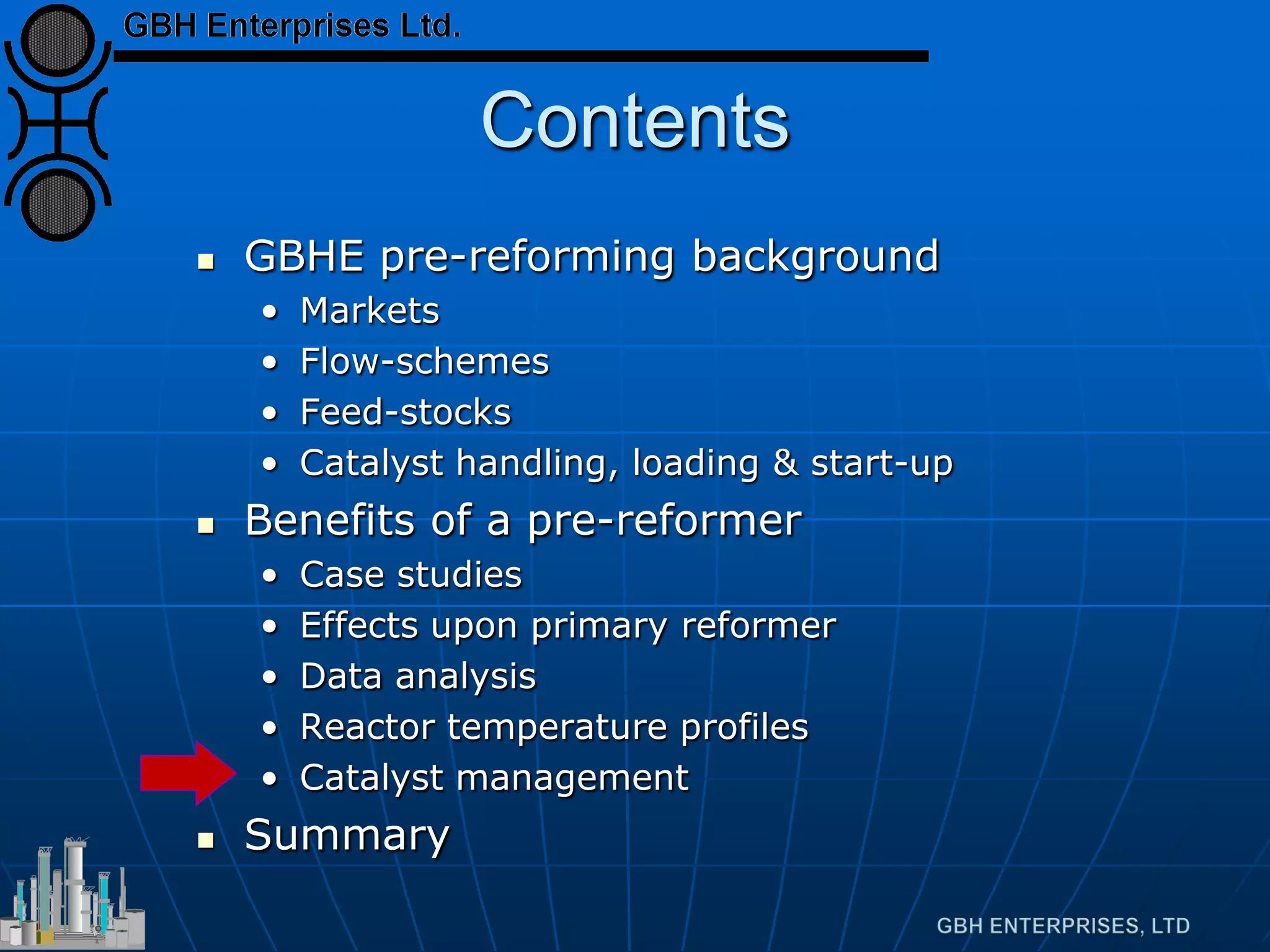
Introduction to pre-reforming and its contents, including benefits and flow-schemes.
Analysis of markets for Town Gas, Hydrogen, Methanol, and Ammonia related to pre-reforming.
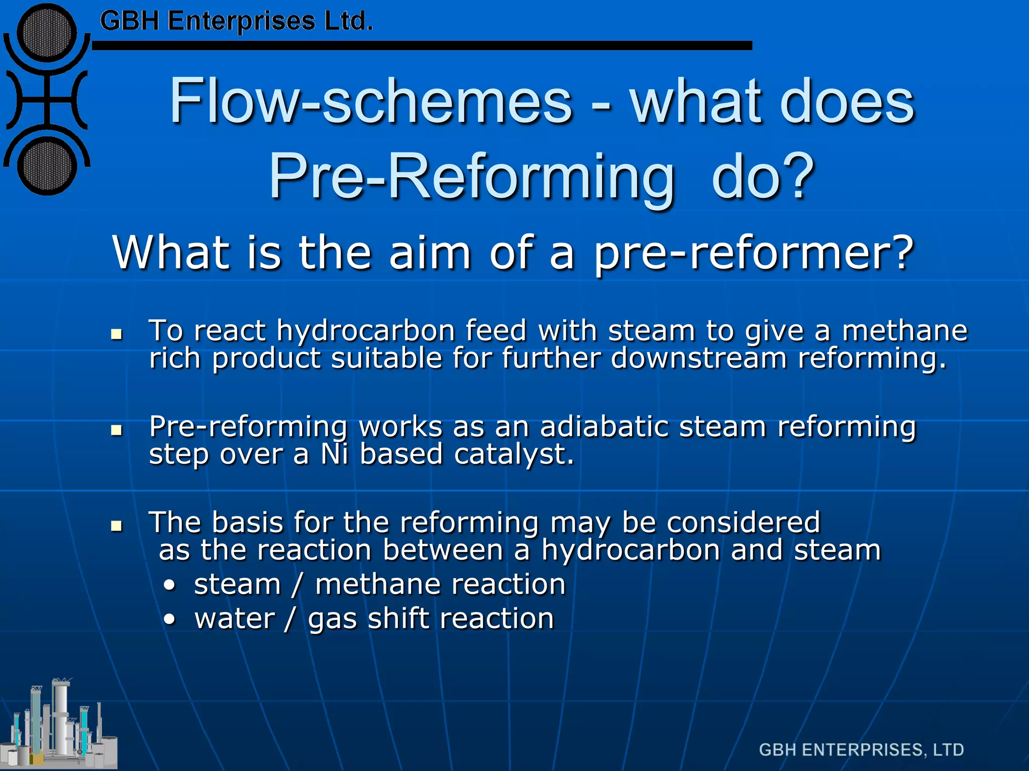
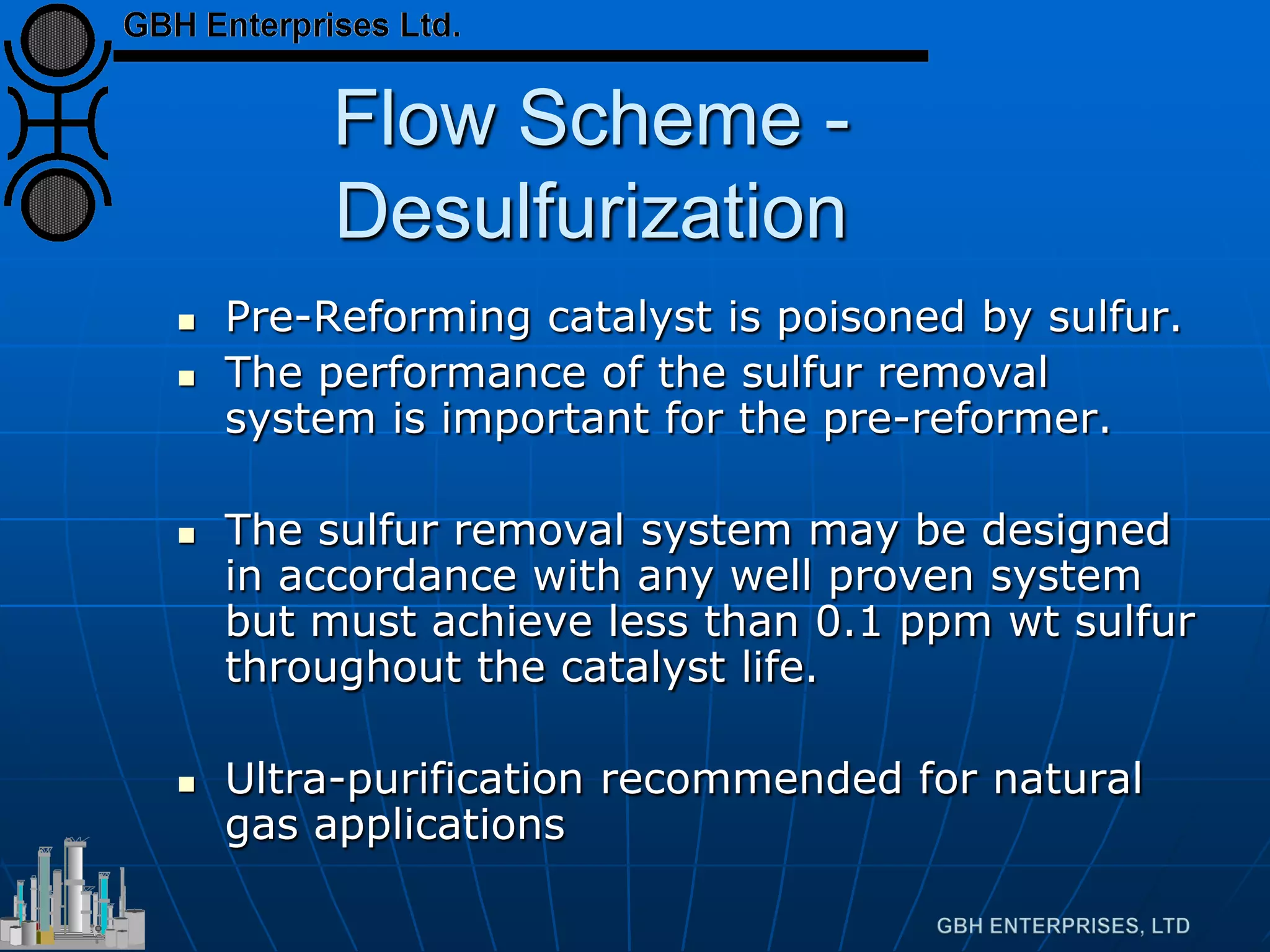
Explains the purpose of pre-reforming, its operation, and the significance of sulfur removal.
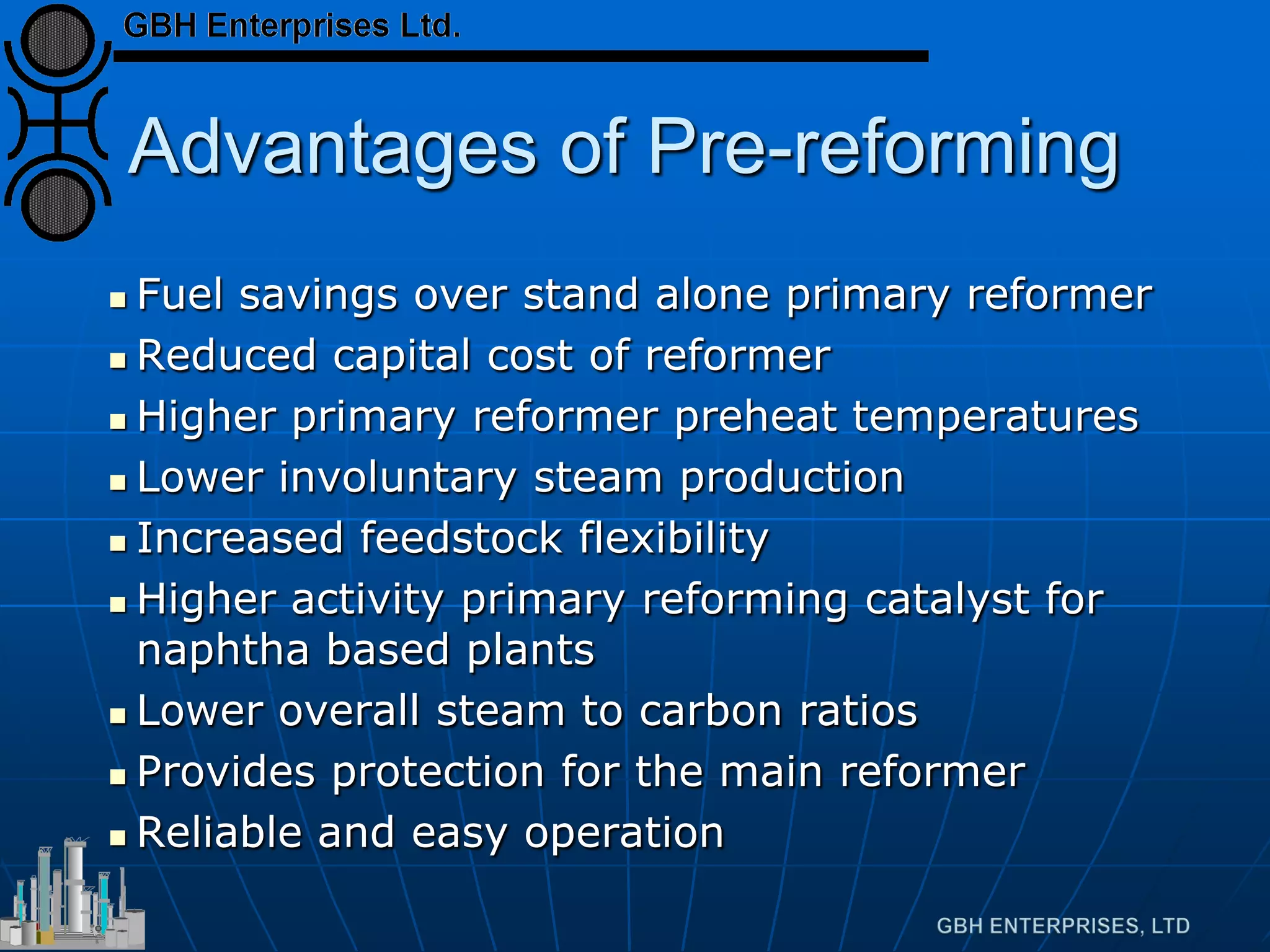
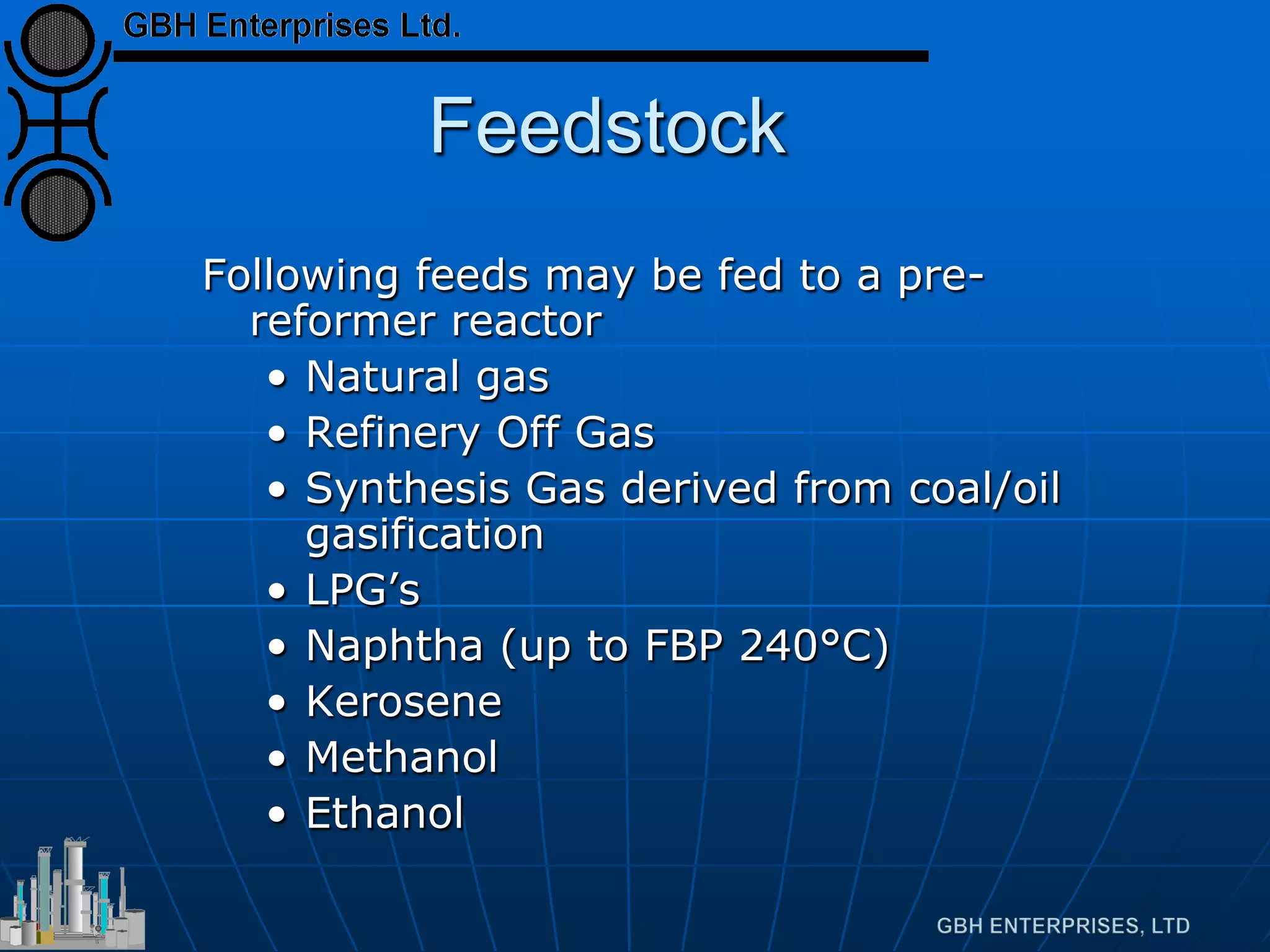
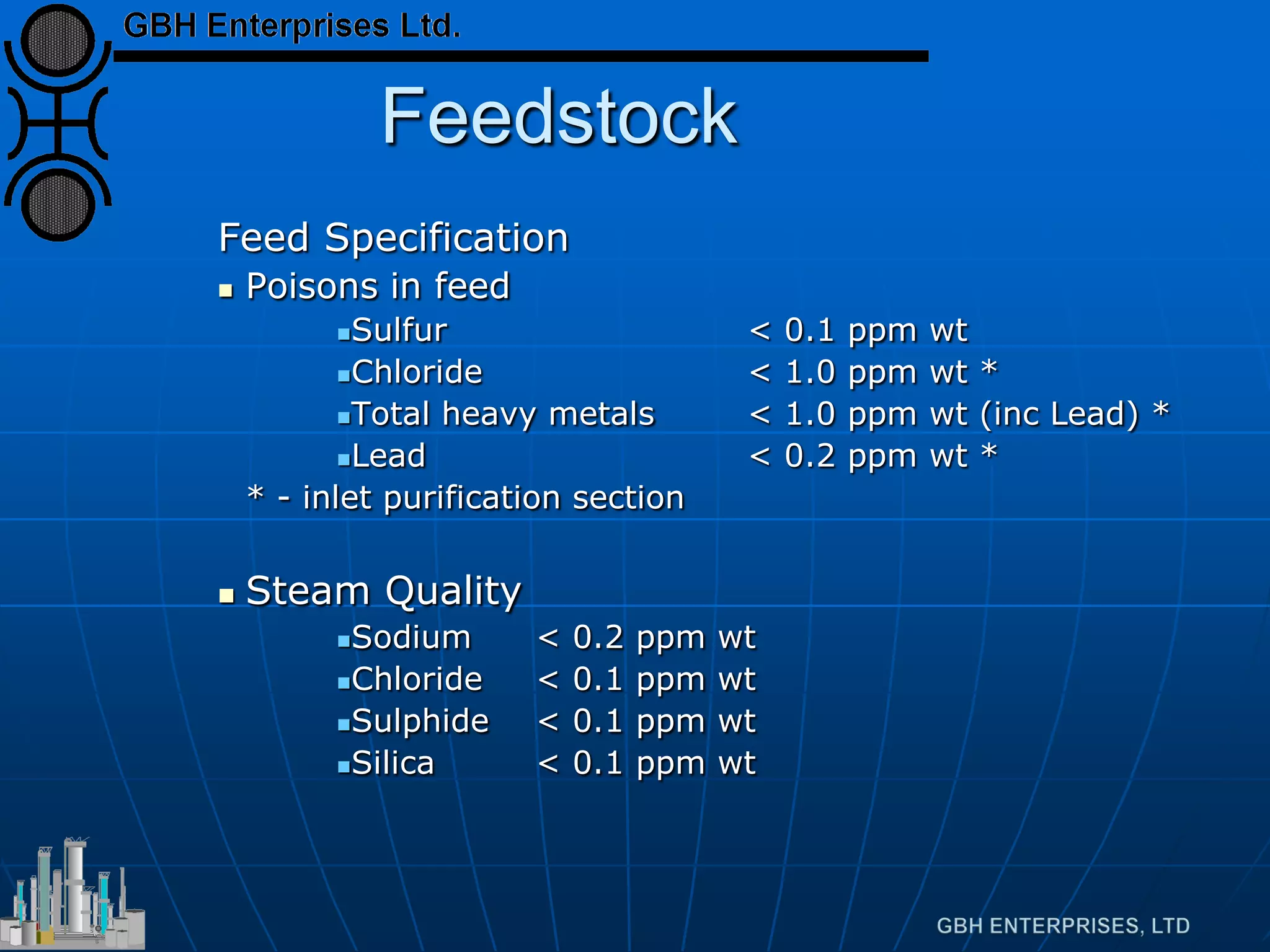
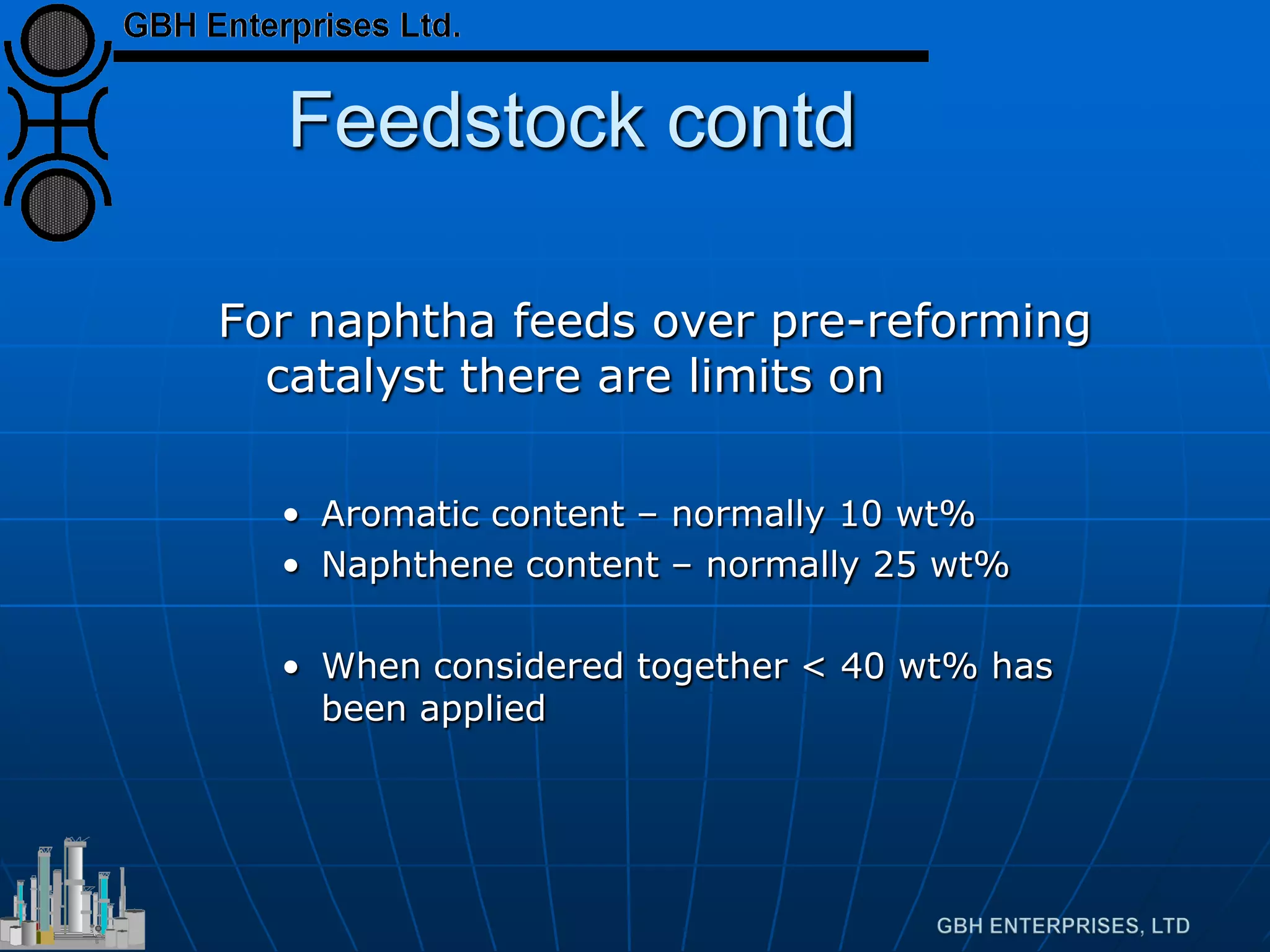
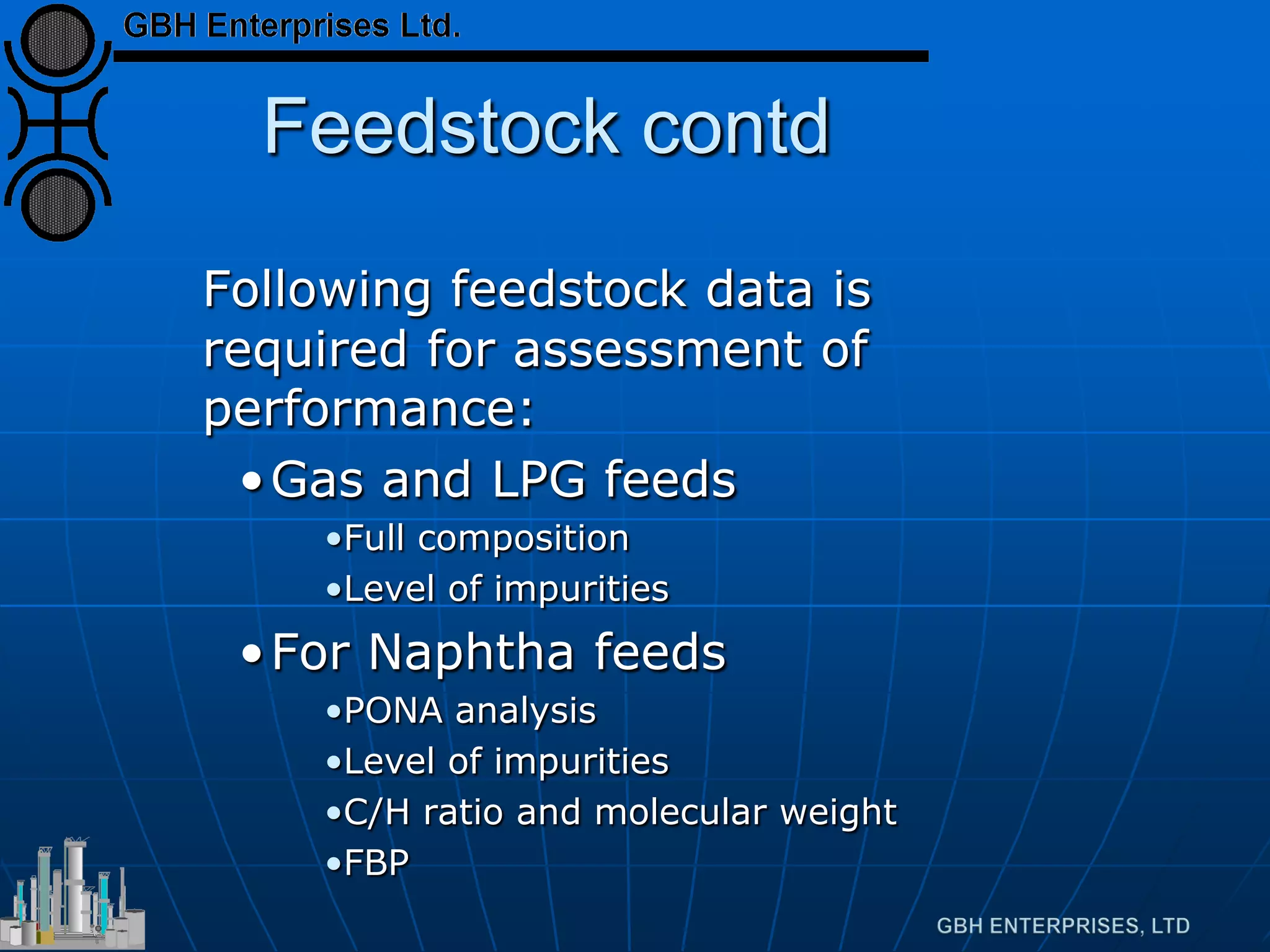
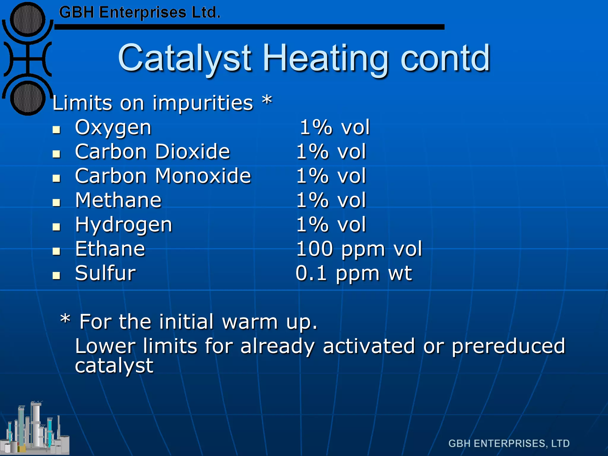
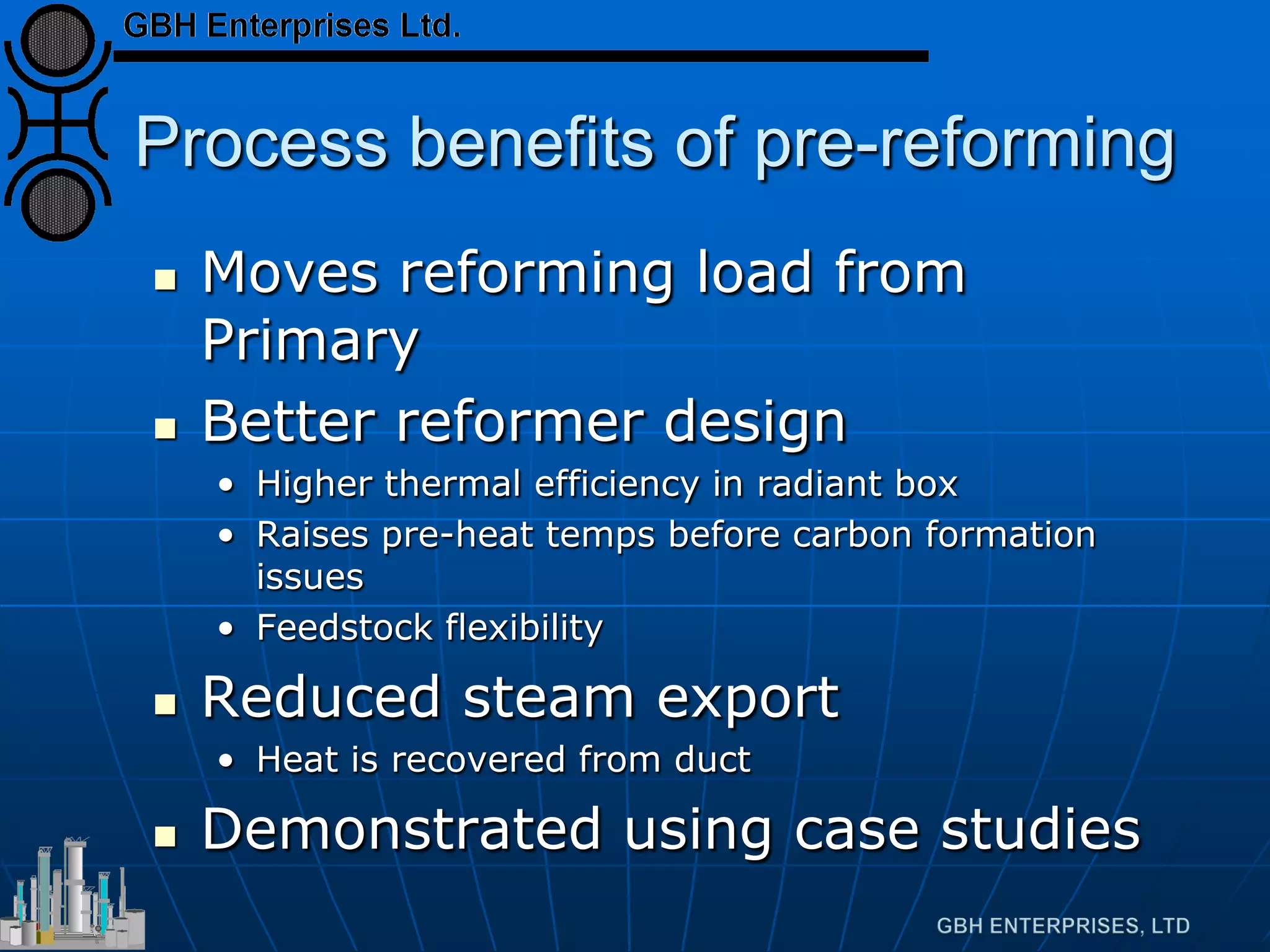
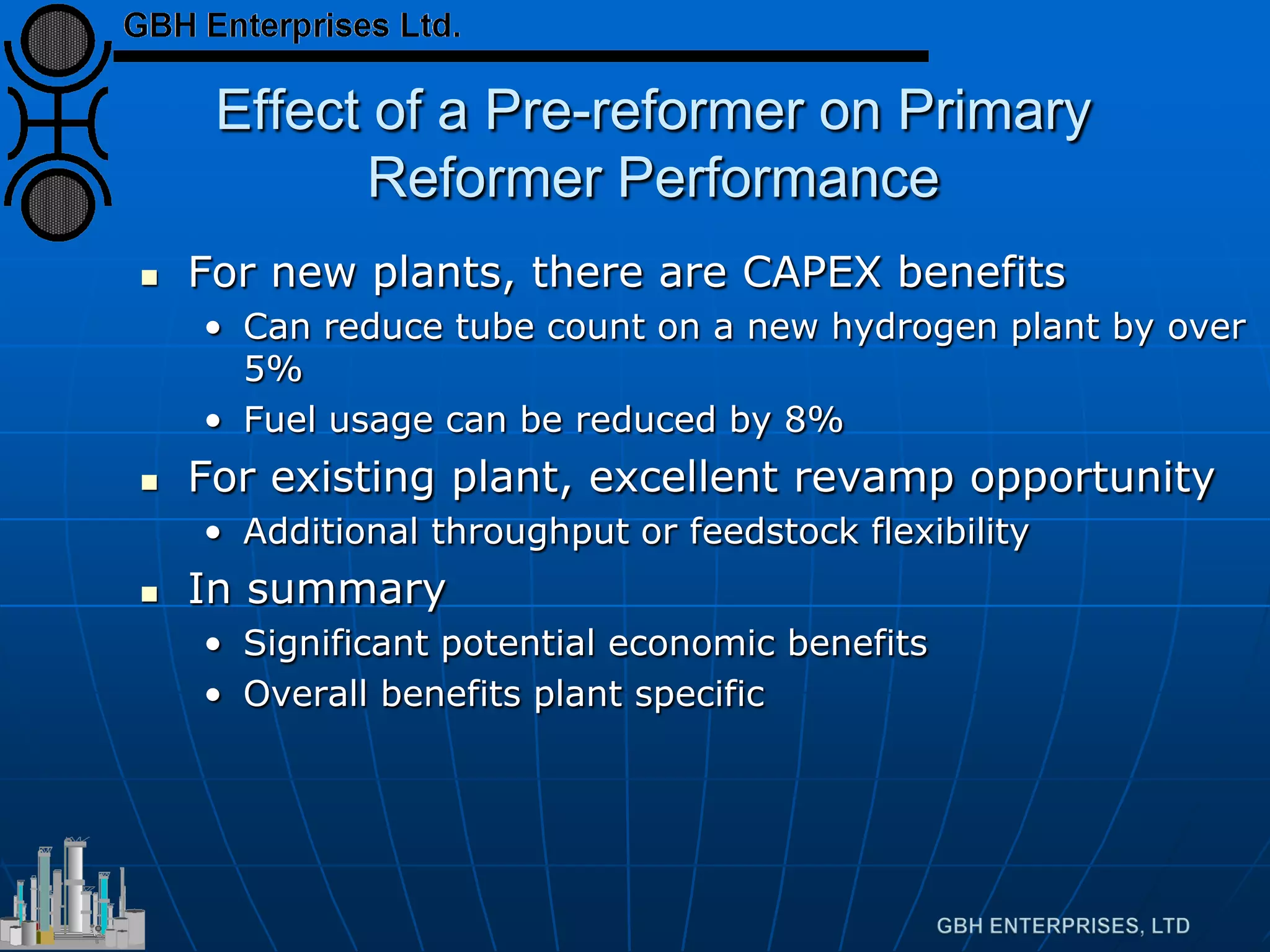
Highlights advantages of pre-reforming such as cost savings, increased flexibility, and crucial feedstock specifications.
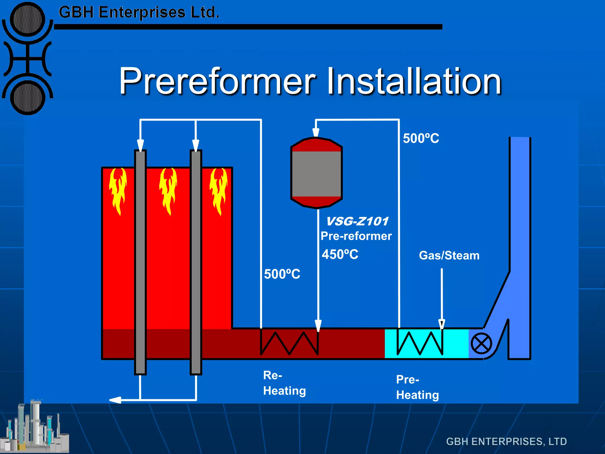
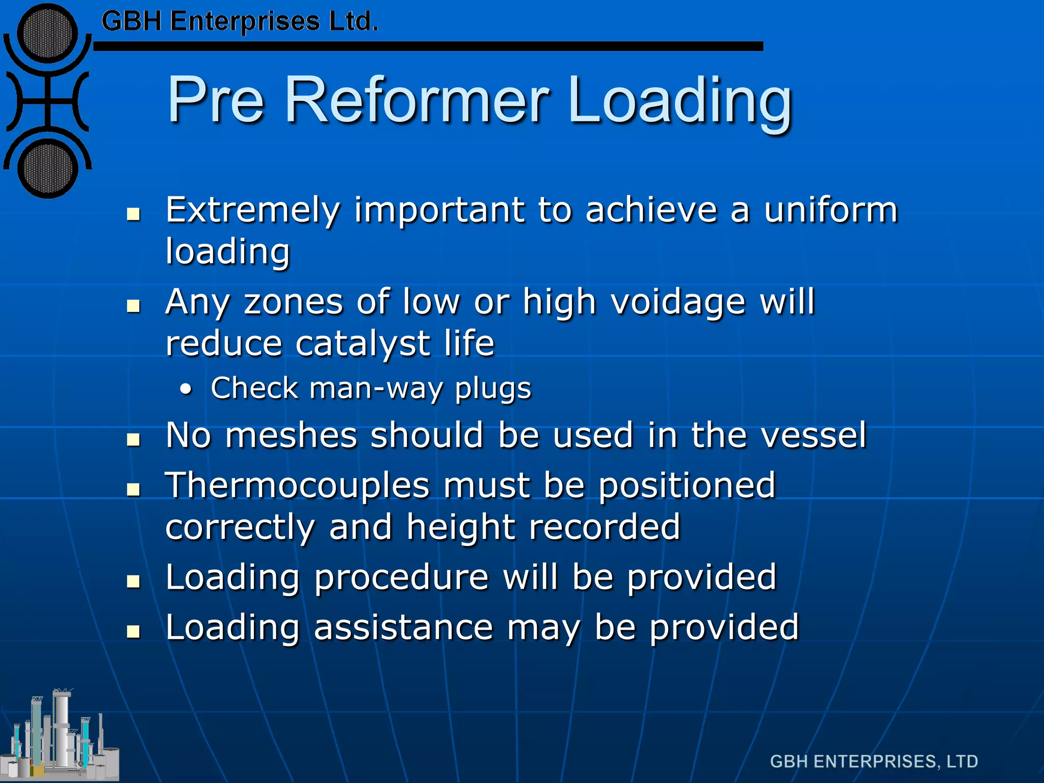
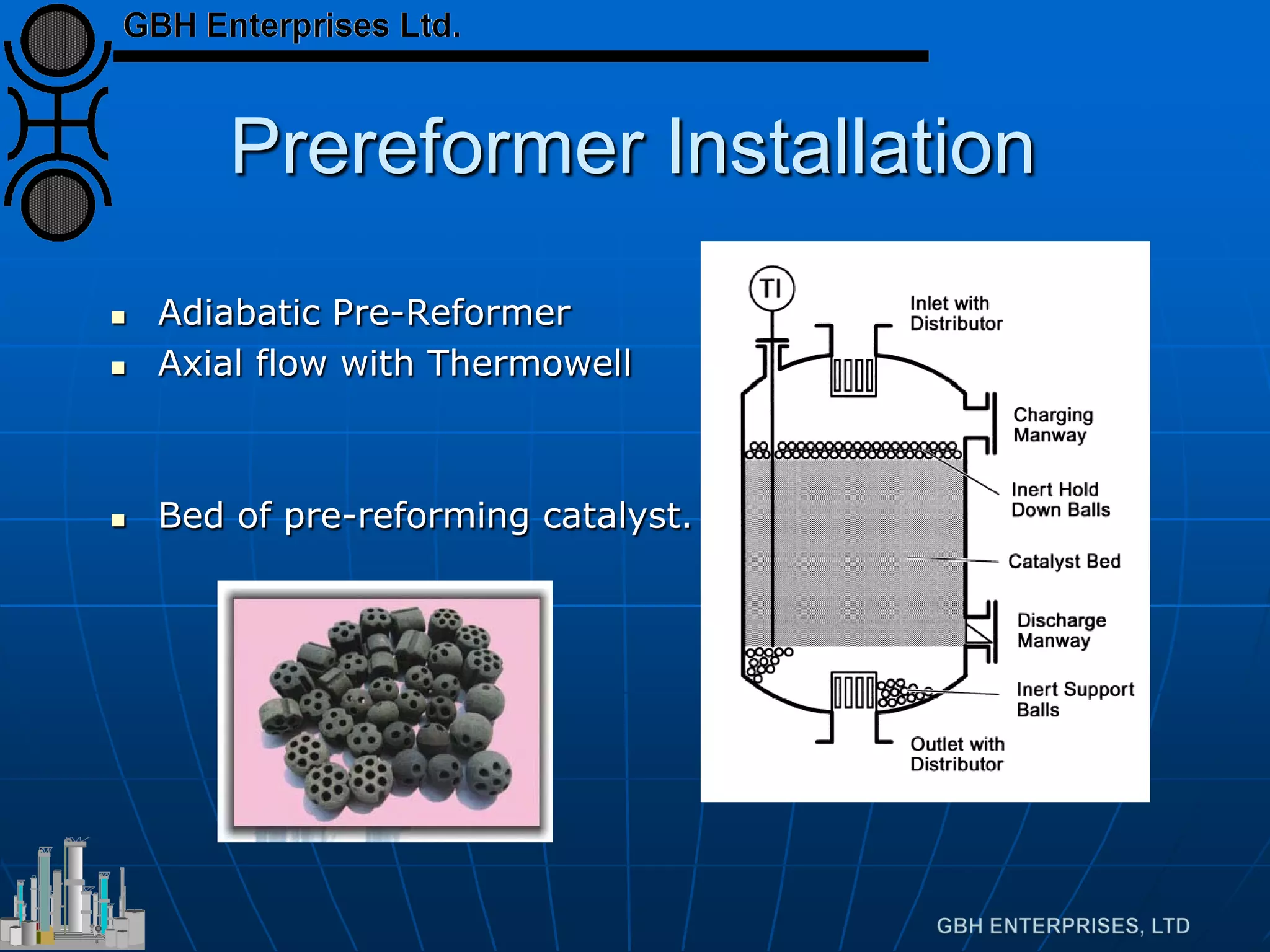
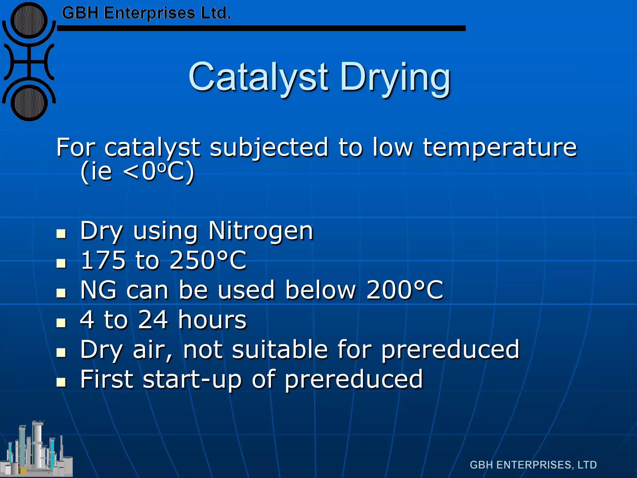
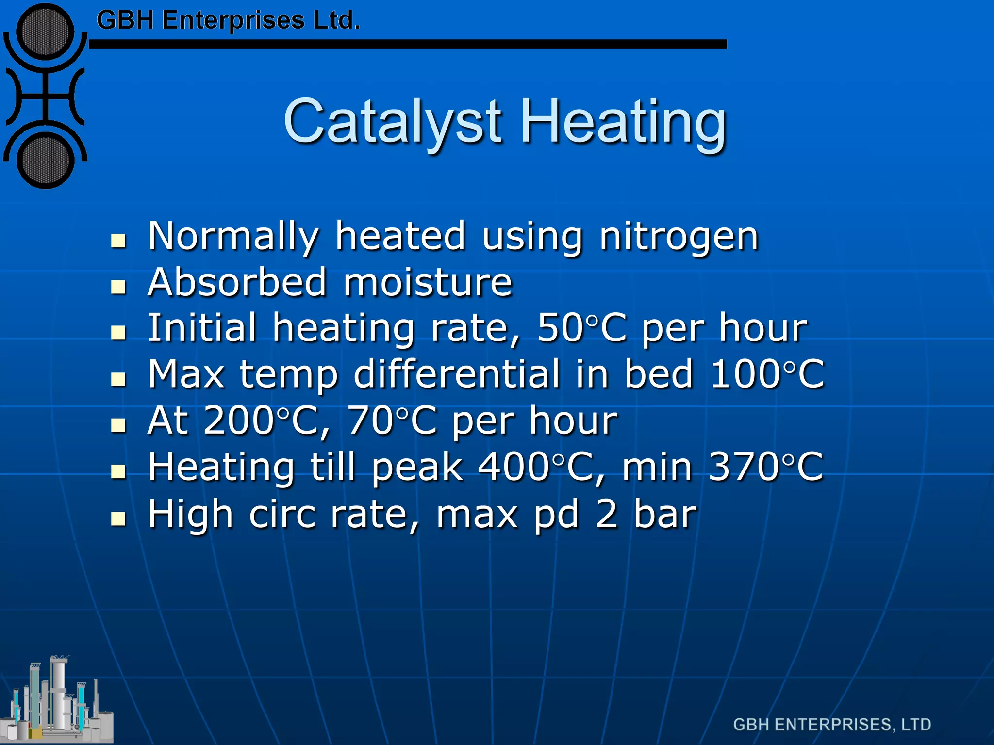
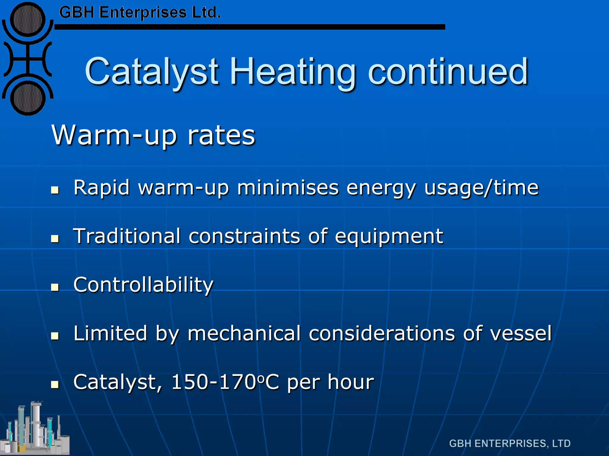
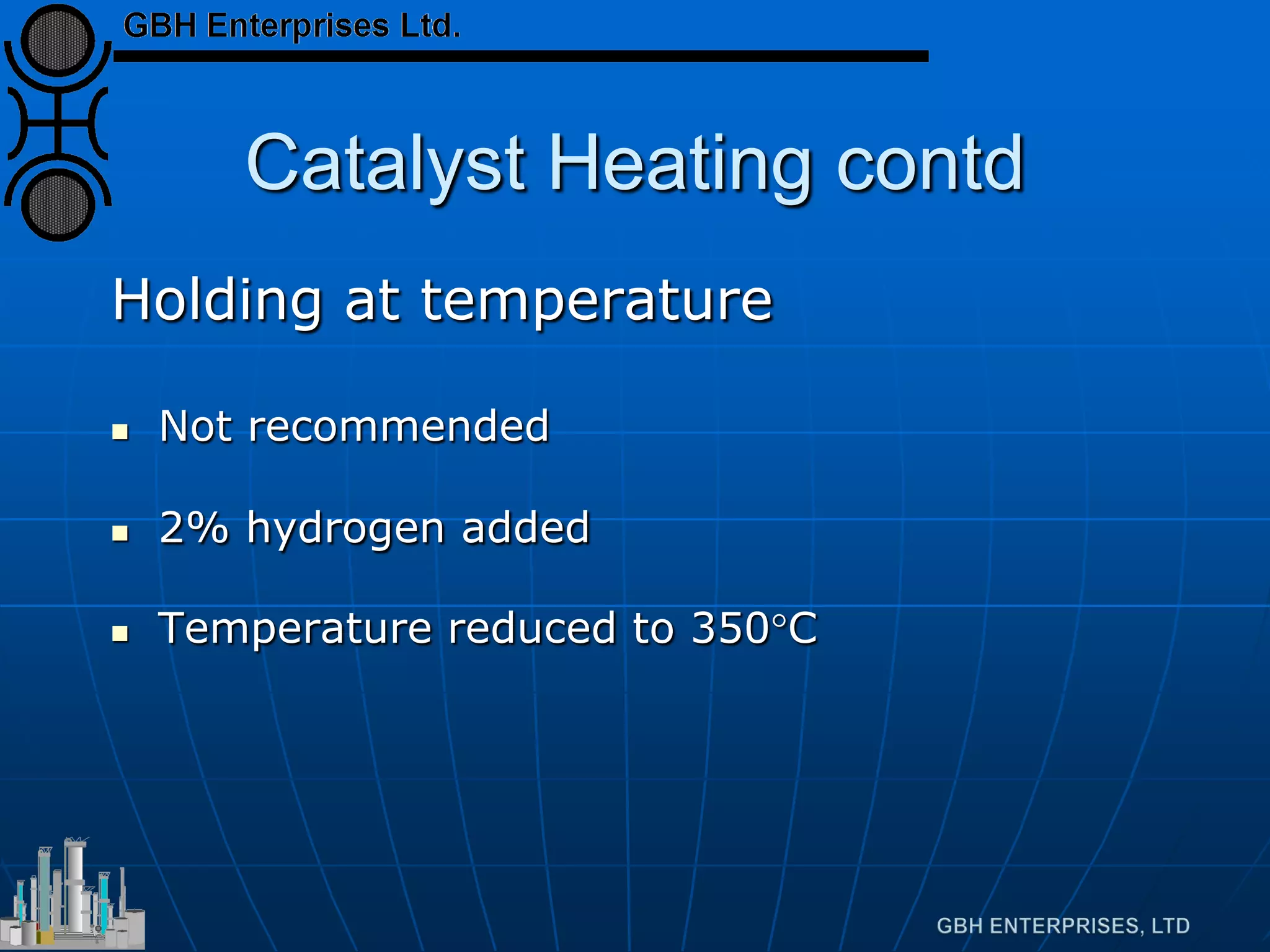
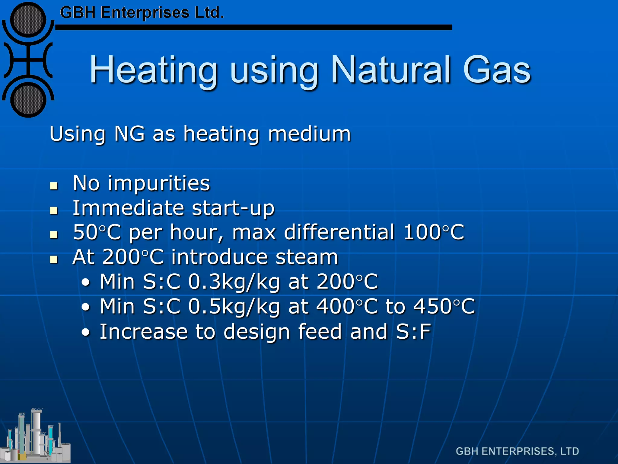
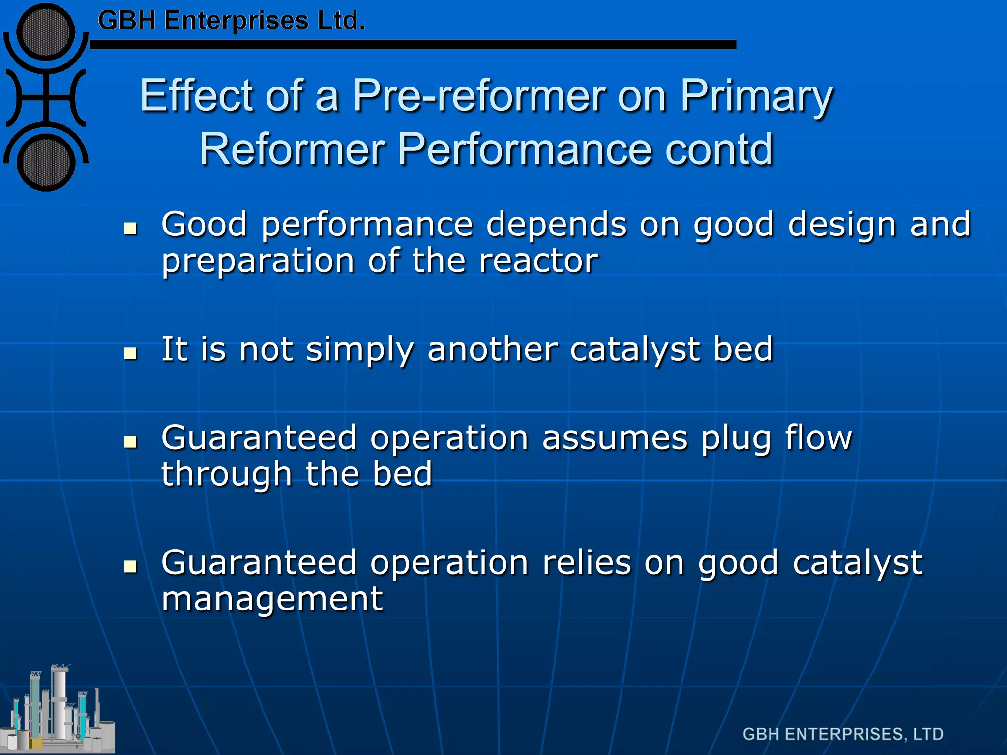
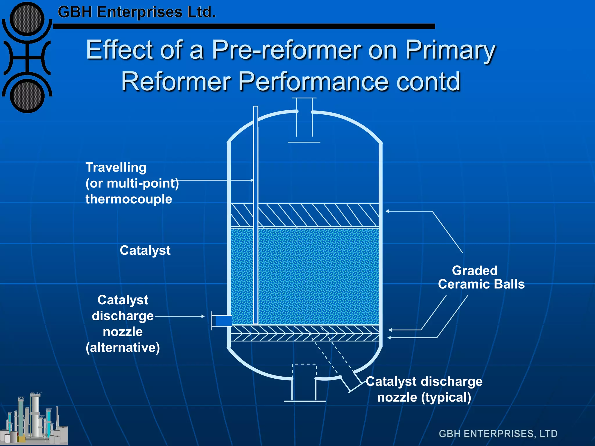
Details about catalyst loading, installation processes, and the importance of careful management.
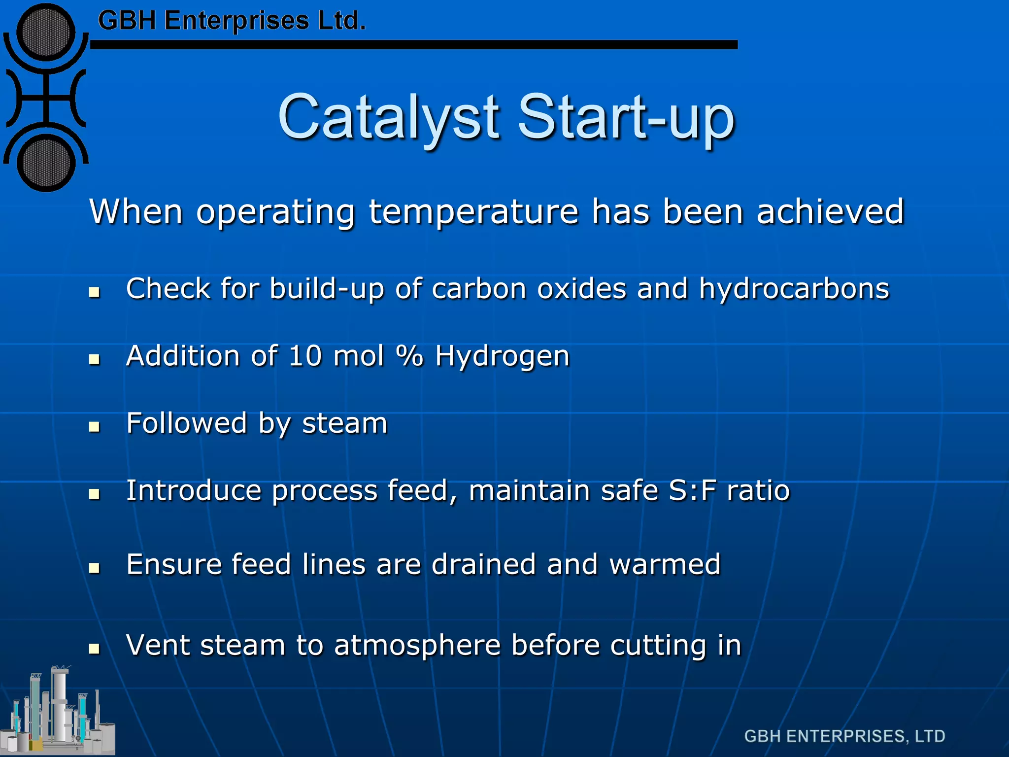
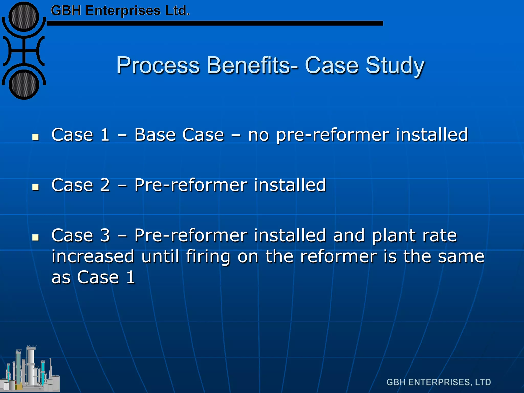
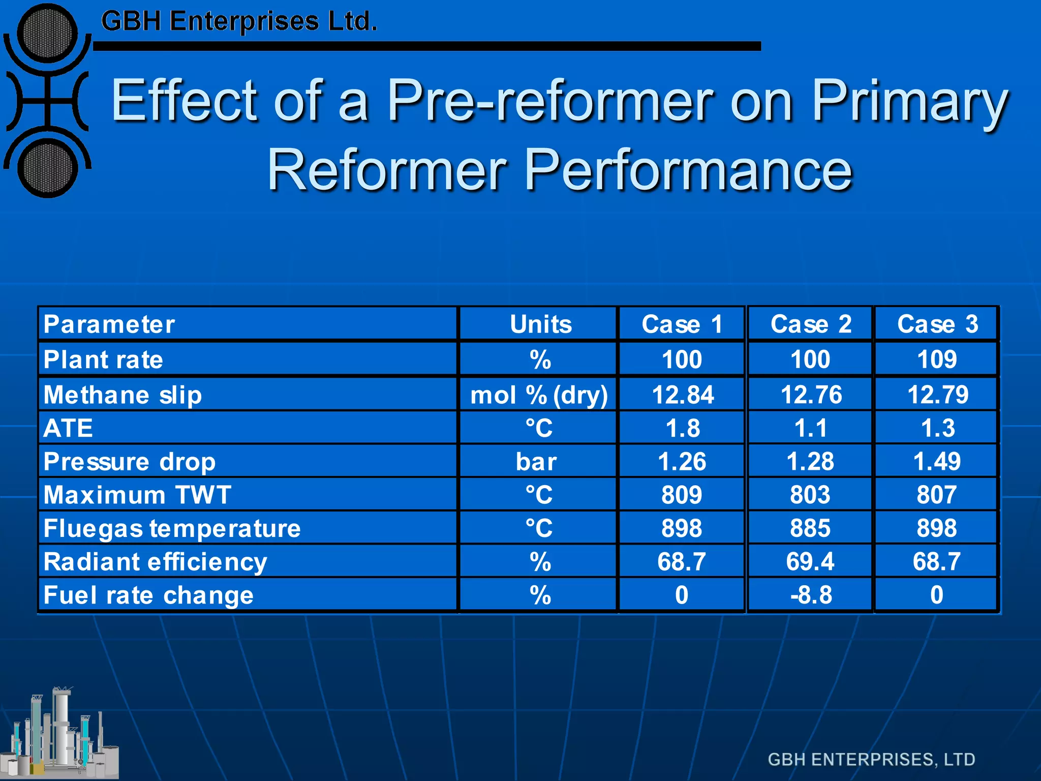
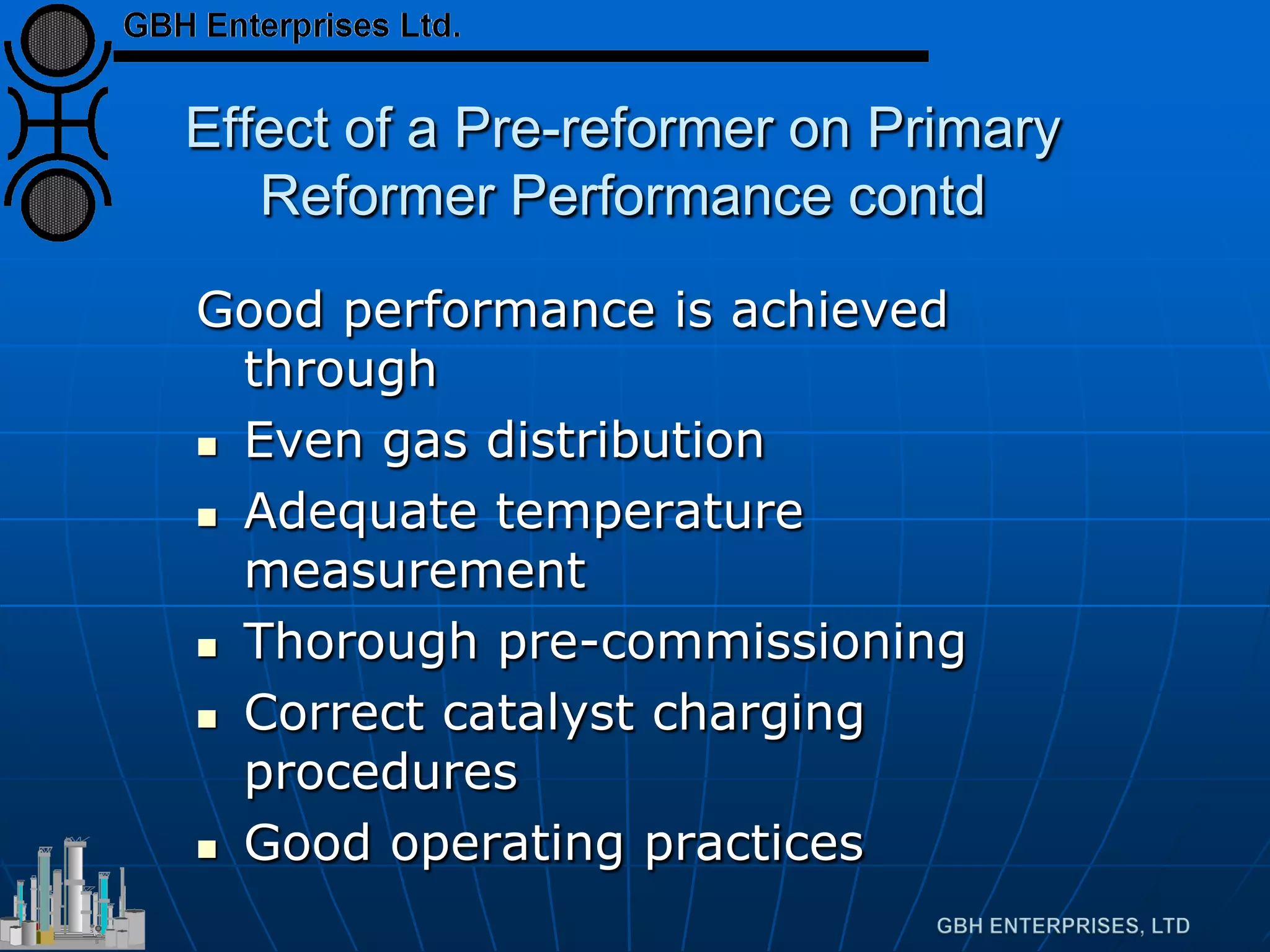
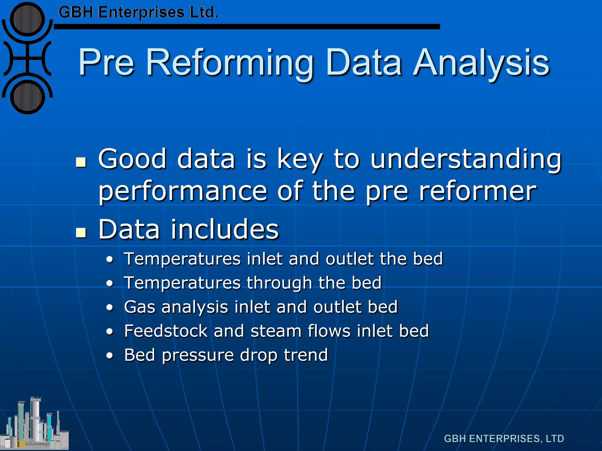
Discusses process benefits using case studies, performance data analysis, and the importance of monitoring.
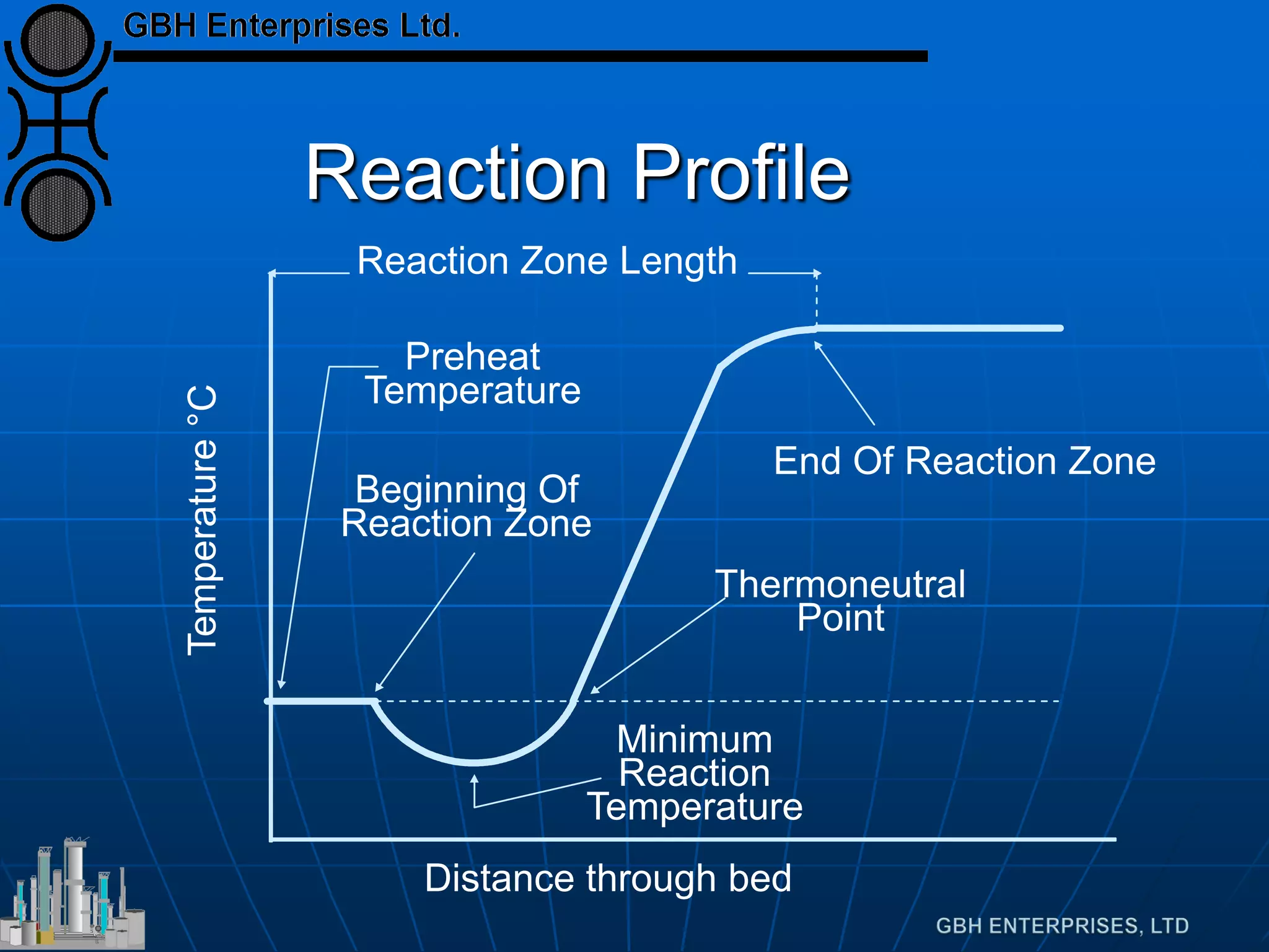
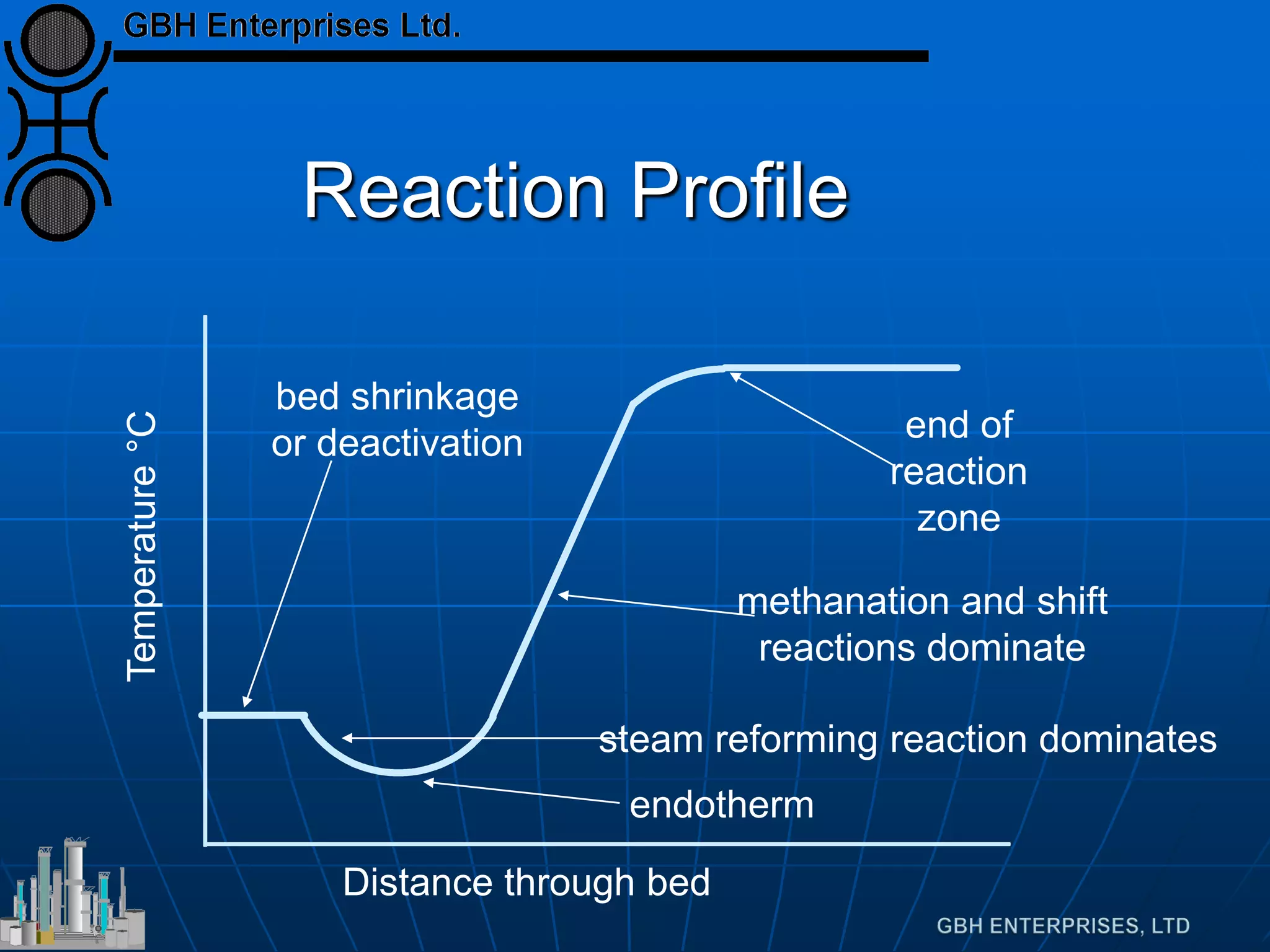
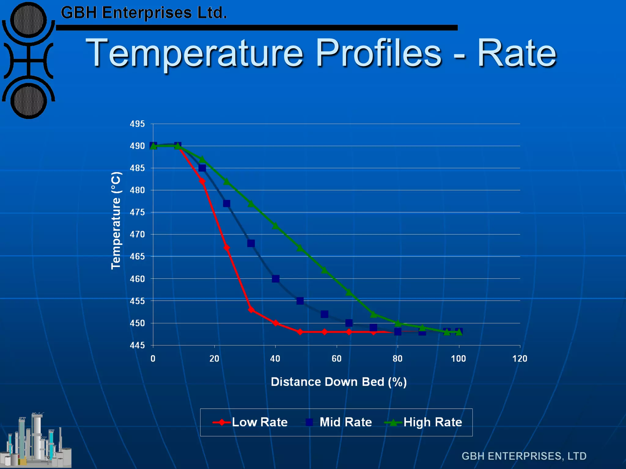
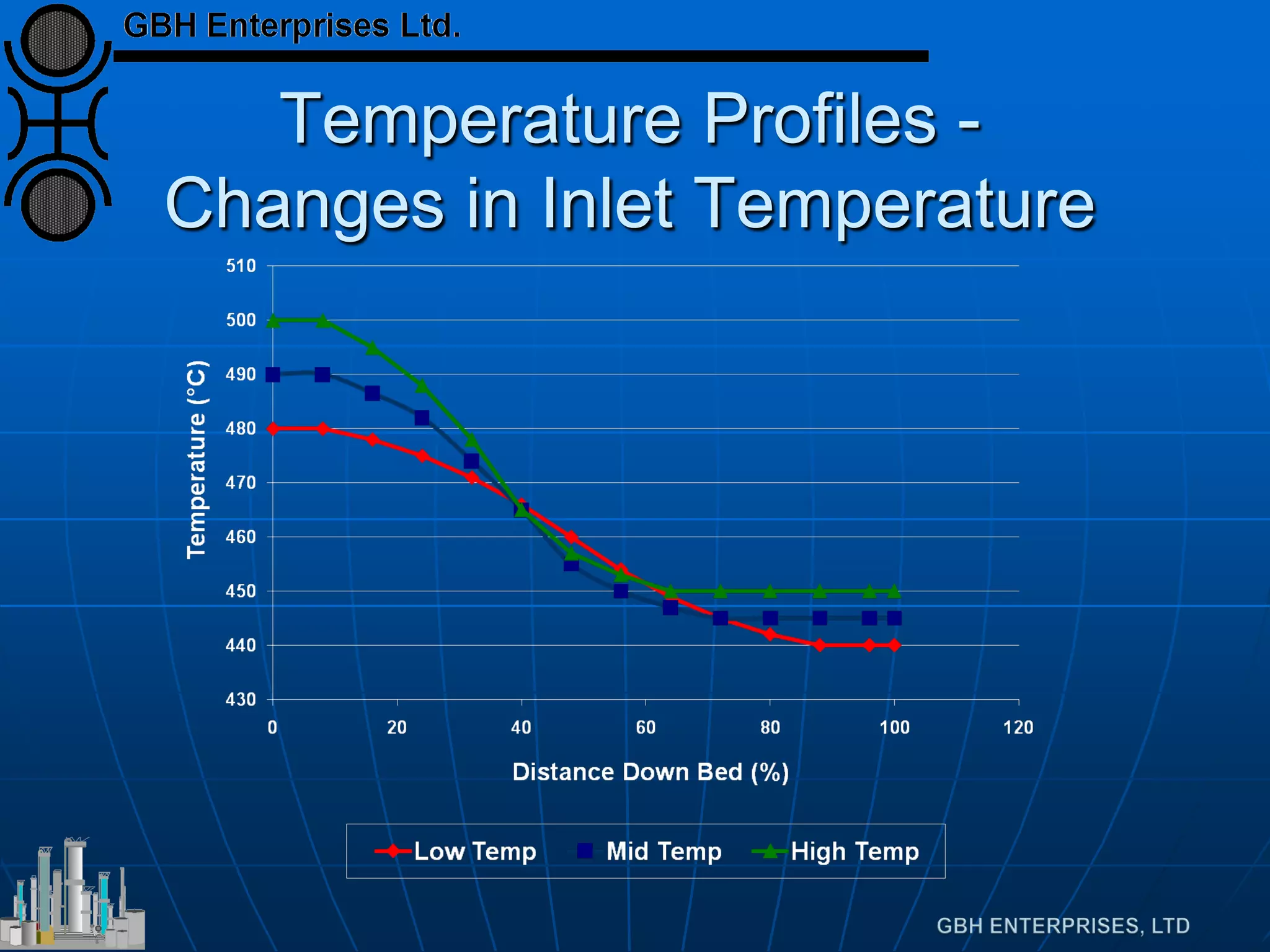
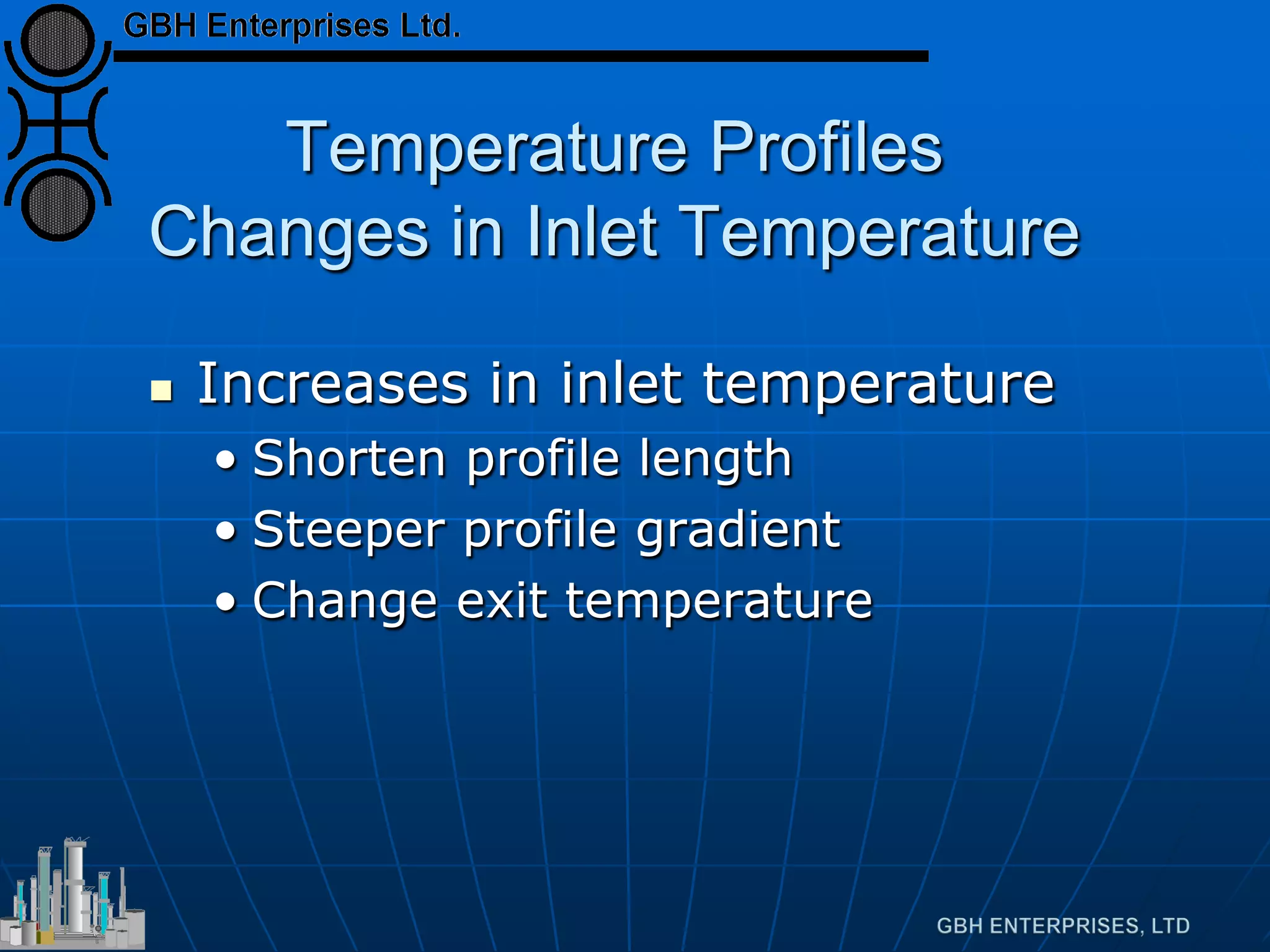
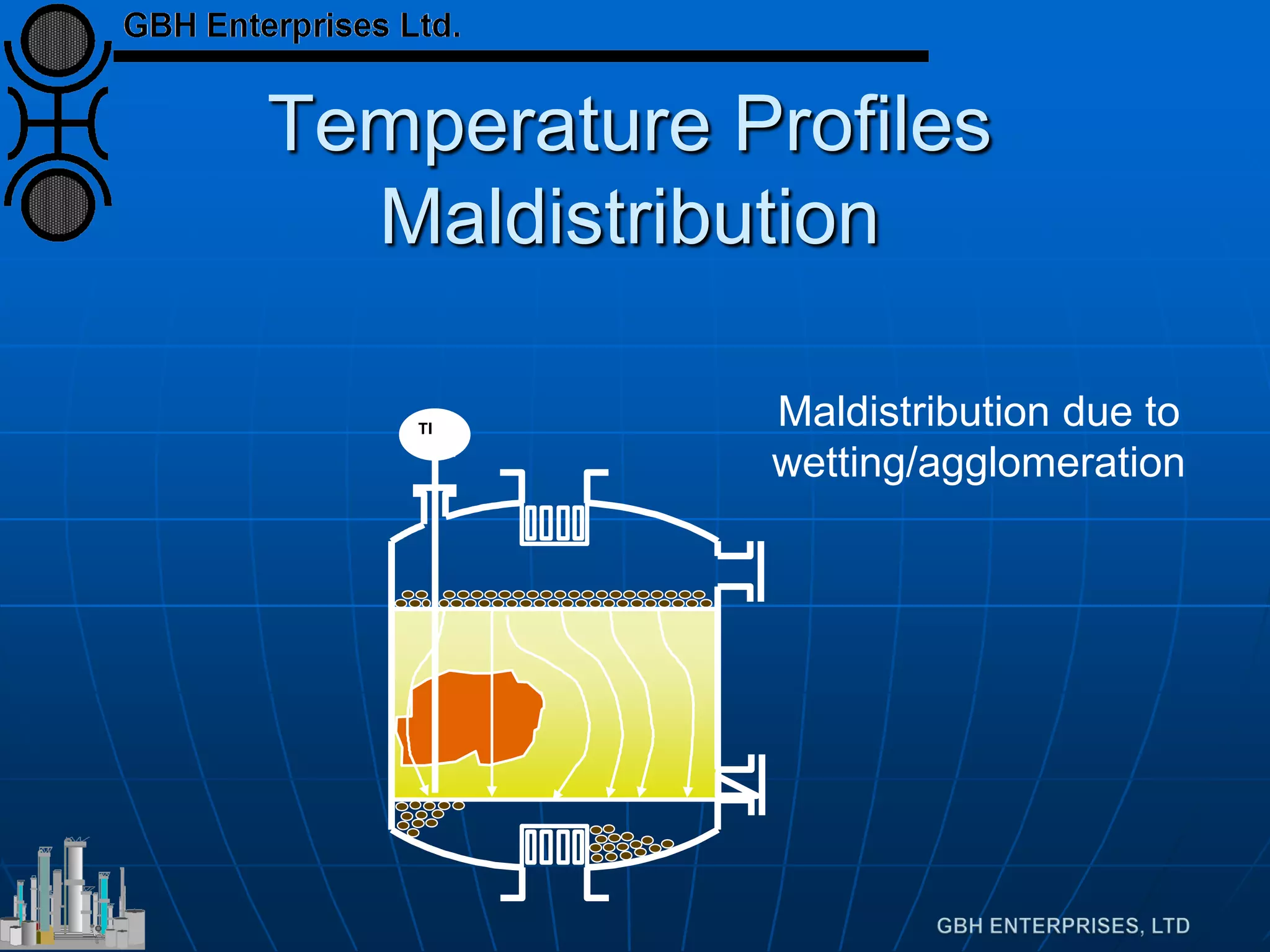
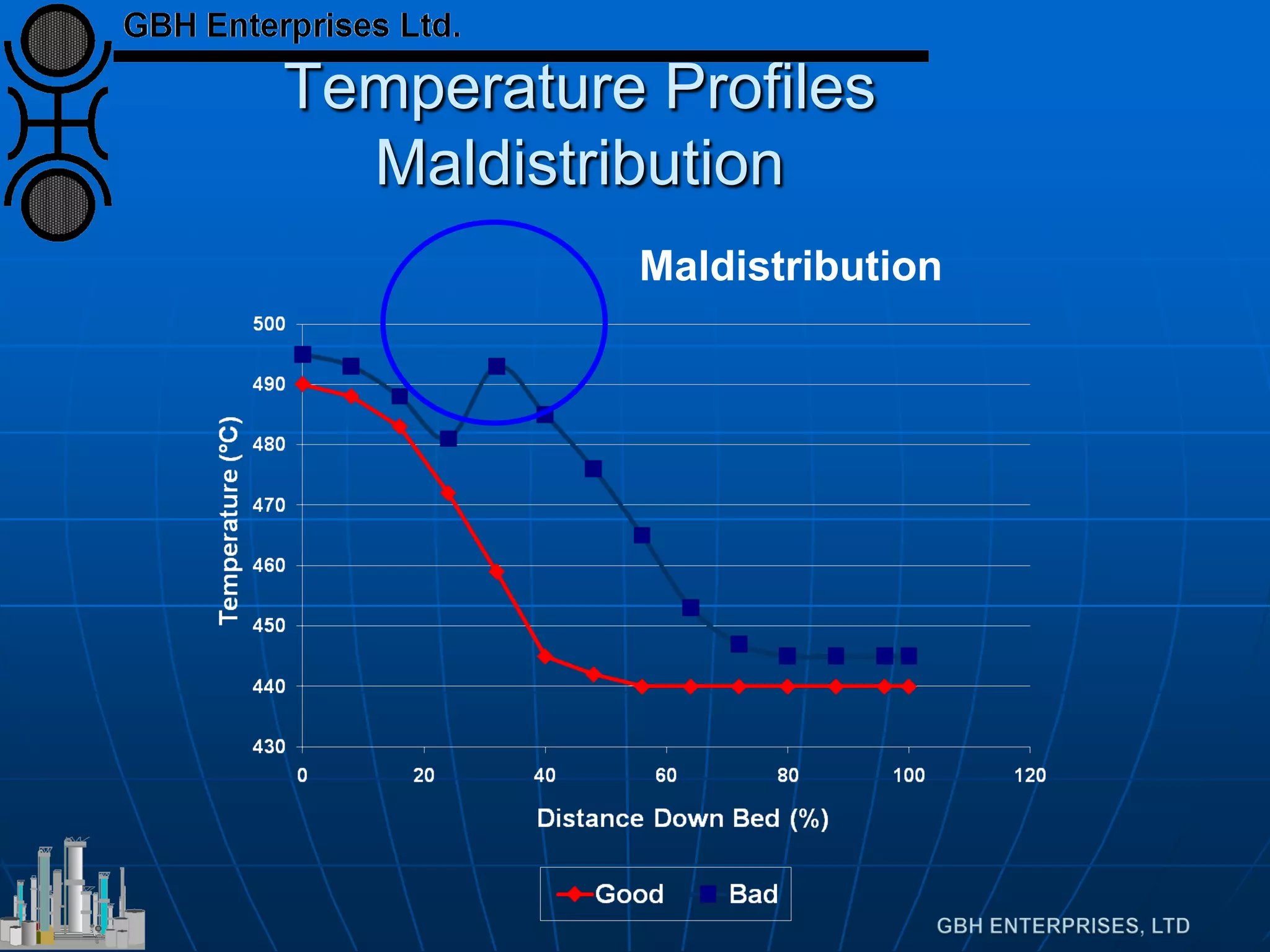
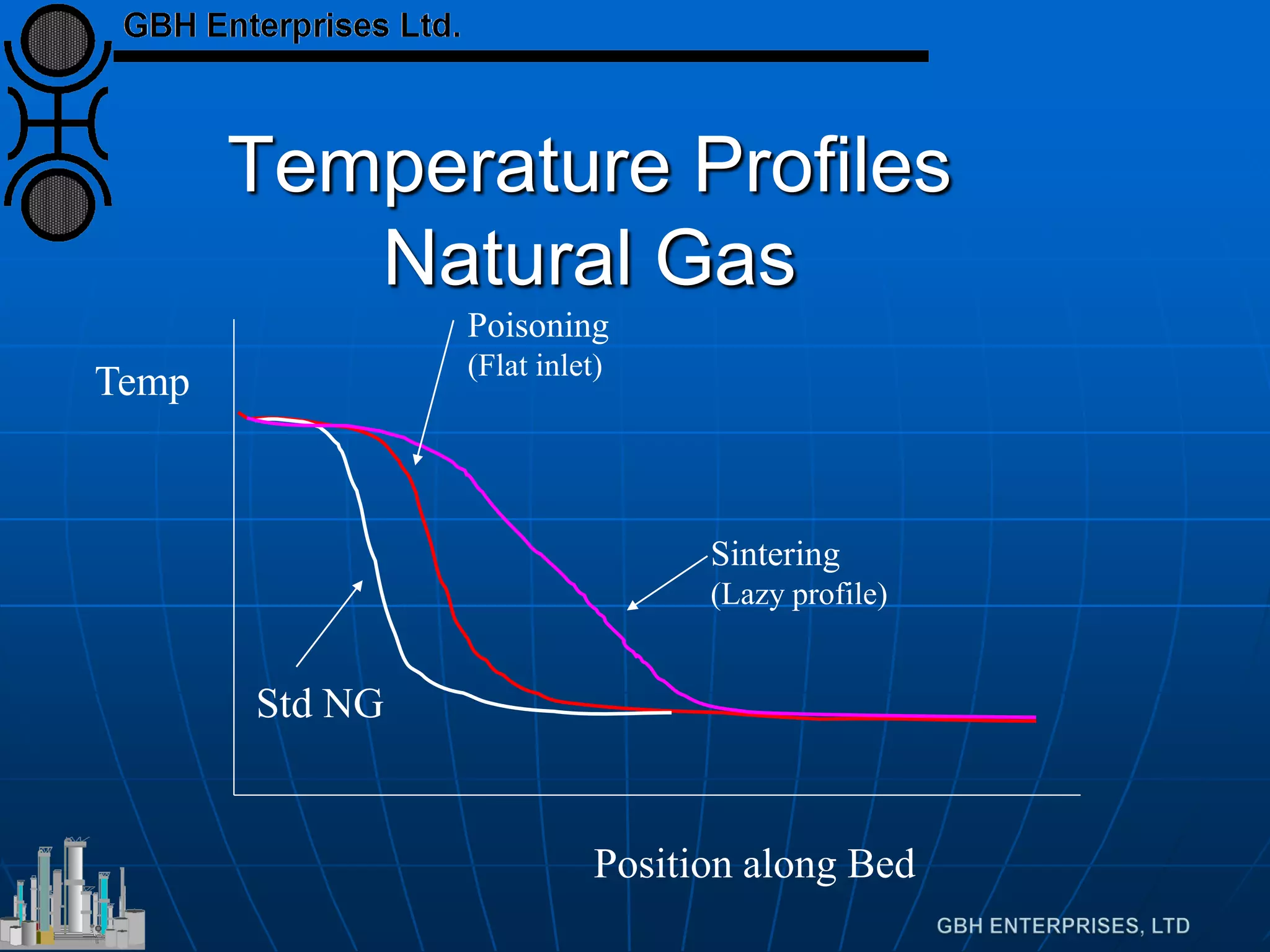
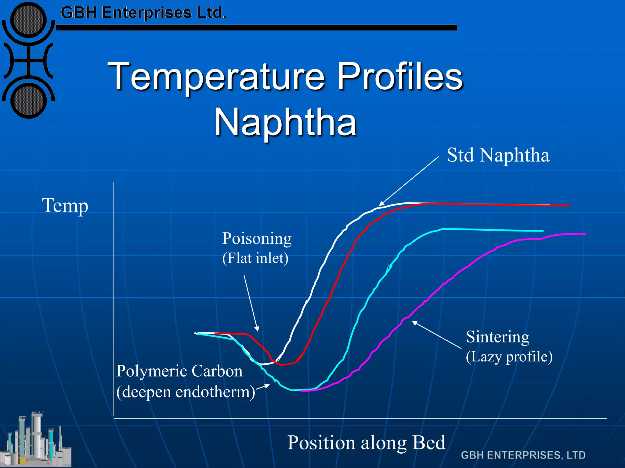
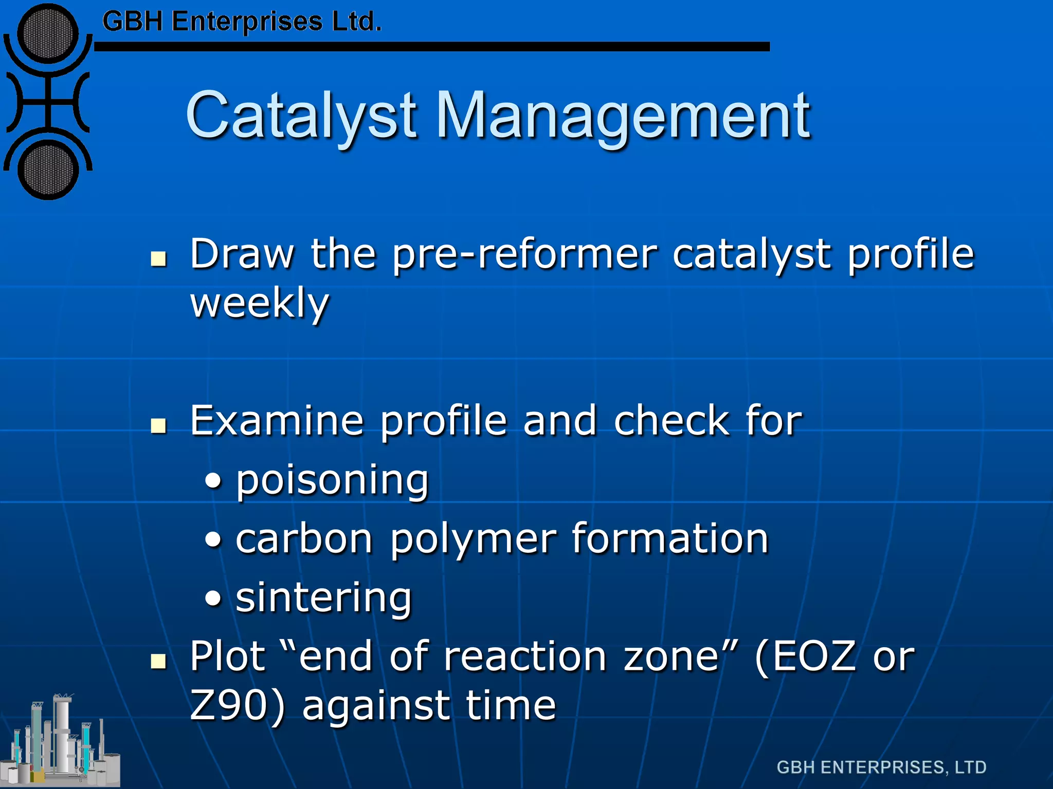
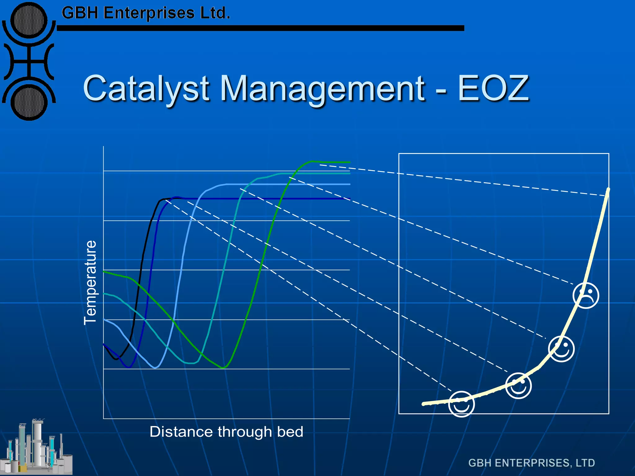
Explains reaction profiles, temperature distribution affects, and monitoring techniques for efficiency.
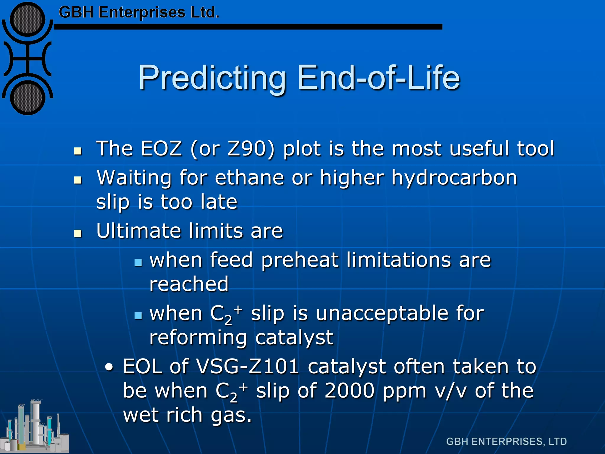
Focuses on maintaining catalyst life through monitoring procedures and effective management for successful pre-reforming.


