Downloaded 307 times
![Refinery Process Stream Purification Refinery Process Catalysts Troubleshooting Refinery Process Catalyst Start-Up / Shutdown
Activation Reduction In-situ Ex-situ Sulfiding Specializing in Refinery Process Catalyst Performance Evaluation Heat & Mass
Balance Analysis Catalyst Remaining Life Determination Catalyst Deactivation Assessment Catalyst Performance
Characterization Refining & Gas Processing & Petrochemical Industries Catalysts / Process Technology - Hydrogen Catalysts /
Process Technology – Ammonia Catalyst Process Technology - Methanol Catalysts / process Technology – Petrochemicals
Specializing in the Development & Commercialization of New Technology in the Refining & Petrochemical Industries
Web Site: www.GBHEnterprises.com
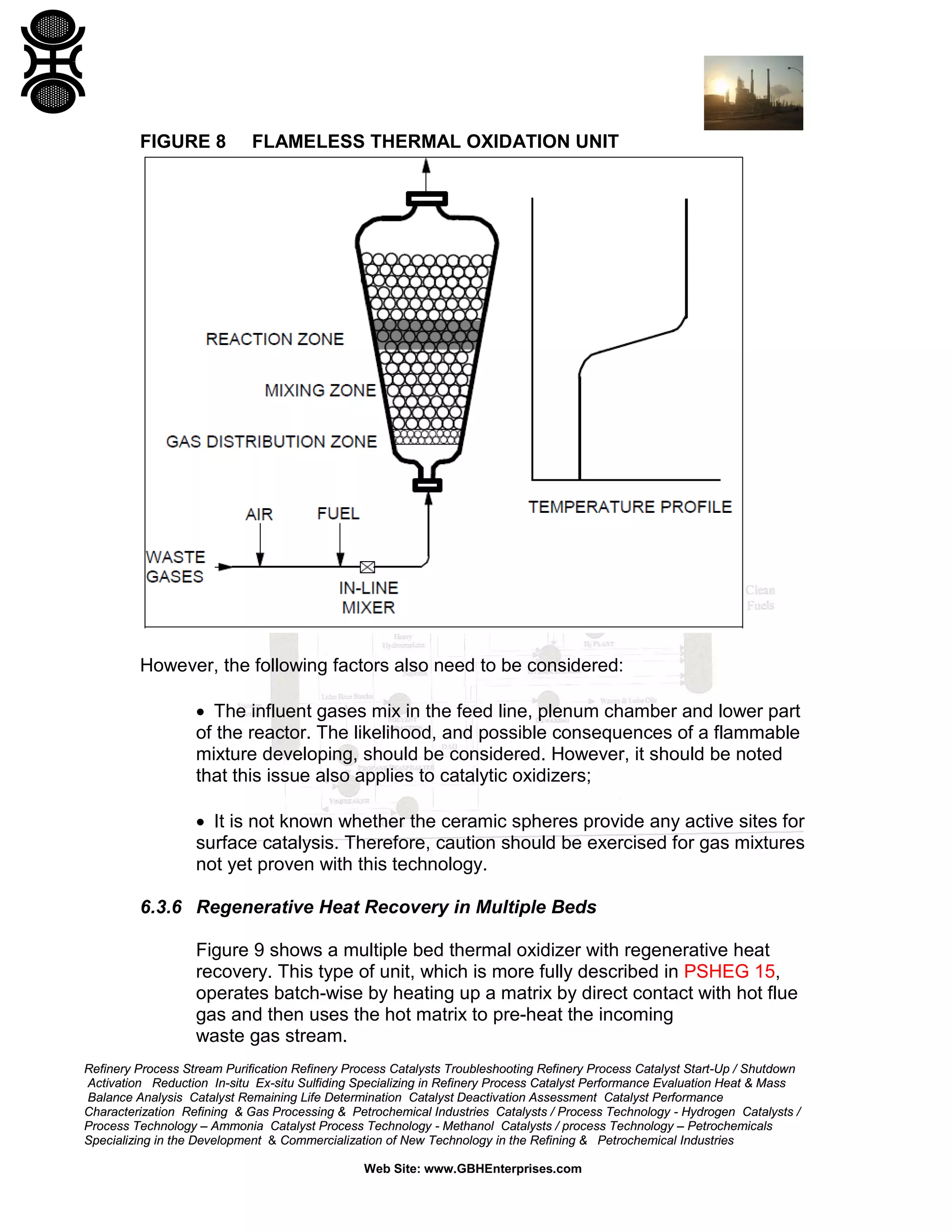
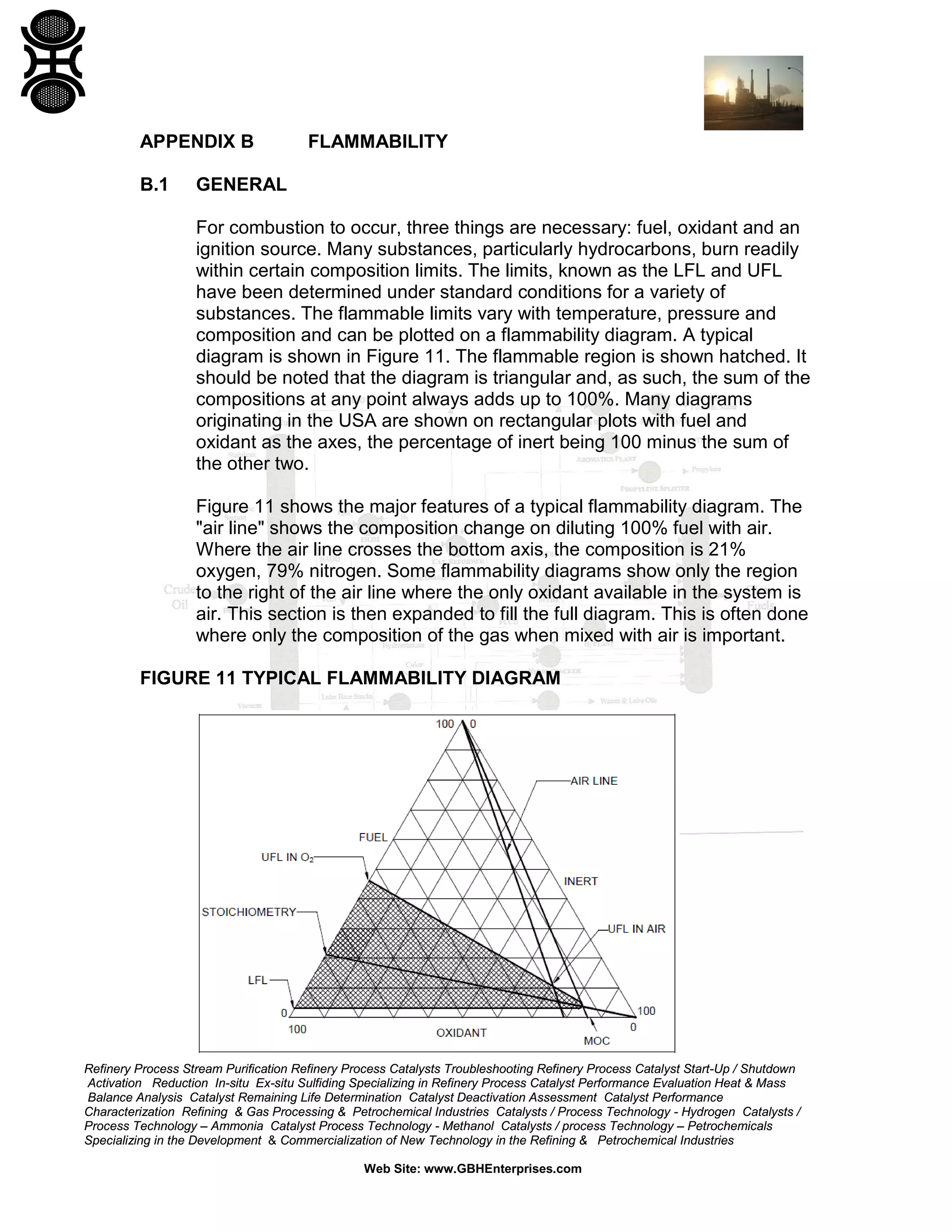
2 ENVIRONMENTAL ISSUES
2.1 Principal Concerns
Some VOCs are toxic and some are implicated in damage to the
stratospheric ozone layer. However, the principal concerns with most
VOCs are:
(a) Their involvement, together with oxides of nitrogen and in the
presence of sunlight, in the production of photochemical oxidants in
the lower atmosphere (see Section 2.2).
(b) Odors which may be offensive at concentrations well below the
Occupational Exposure Limit (OEL).
VOCs can be classified according to their Photochemical Ozone Creation
Potential (POCP) referenced to a standard of unity for ethylene (see
Section 2.3). Ozone is the photochemical oxidant that has been studied
most widely but there are others including peroxyacetyl nitrate (PAN) and
hydrogen peroxide. Ozone can pose a health risk and cause
environmental damage (see Section 2.4).
Some VOCs also present an odor nuisance, even at very low
concentrations. For example, ethyl acrylate has an odor threshold of about
0.02 ppb. This can create major difficulties for design and operation as the
emission to atmosphere of only a few mg/sec can cause odor problems. It
is therefore vital that odorous materials are contained within process
equipment. Where this cannot be achieved, then destruction or capture
techniques should be very efficient and stacks discharging directly to
atmosphere should usually be very tall.
2.2 Mechanisms for Ozone Formation
The atmospheric chemistry of ozone formation is very complex and
involves a multitude of interacting chemical reactions [Refs. 2 & 3]. The
principal reactions are shown below which illustrate the involvement of
VOCs in a simplified form.](https://image.slidesharecdn.com/designventgascollectiondestructionsystems-150310004411-conversion-gate01/75/DESIGN-OF-VENT-GAS-COLLECTION-AND-DESTRUCTION-SYSTEMS-8-2048.jpg)
![Refinery Process Stream Purification Refinery Process Catalysts Troubleshooting Refinery Process Catalyst Start-Up / Shutdown
Activation Reduction In-situ Ex-situ Sulfiding Specializing in Refinery Process Catalyst Performance Evaluation Heat & Mass
Balance Analysis Catalyst Remaining Life Determination Catalyst Deactivation Assessment Catalyst Performance
Characterization Refining & Gas Processing & Petrochemical Industries Catalysts / Process Technology - Hydrogen Catalysts /
Process Technology – Ammonia Catalyst Process Technology - Methanol Catalysts / process Technology – Petrochemicals
Specializing in the Development & Commercialization of New Technology in the Refining & Petrochemical Industries
Web Site: www.GBHEnterprises.com
Nitrogen dioxide absorbs natural radiation and breaks down into nitric
oxide and oxygen radicals:
The oxygen radicals combine with oxygen to form ozone:
However, ozone oxidizes nitric oxide to nitrogen dioxide:
Hence there is a natural balance of ozone concentrations at ground level
involving oxides of nitrogen. However, peroxy radicals (RO2) produced by
the attack of hydroxyl radicals (OH) on VOCs act as a sink for nitric oxide
and thereby disturb the above equilibrium towards higher concentrations
of ozone:
It is believed that hydroxyl radicals are formed in the atmosphere by
photochemical dissociation of ozone and subsequent reaction with water.
It should be noted that the above reactions require the simultaneous
presence of precursors in the appropriate meteorological conditions.
Furthermore, not only are some of these reactions slow, but ozone, once
formed, can persist for several days and so may be transported long
distances. Therefore, elevated ozone concentrations often appear over
widespread areas up to several hundred kilometers from the sources of
the precursors.
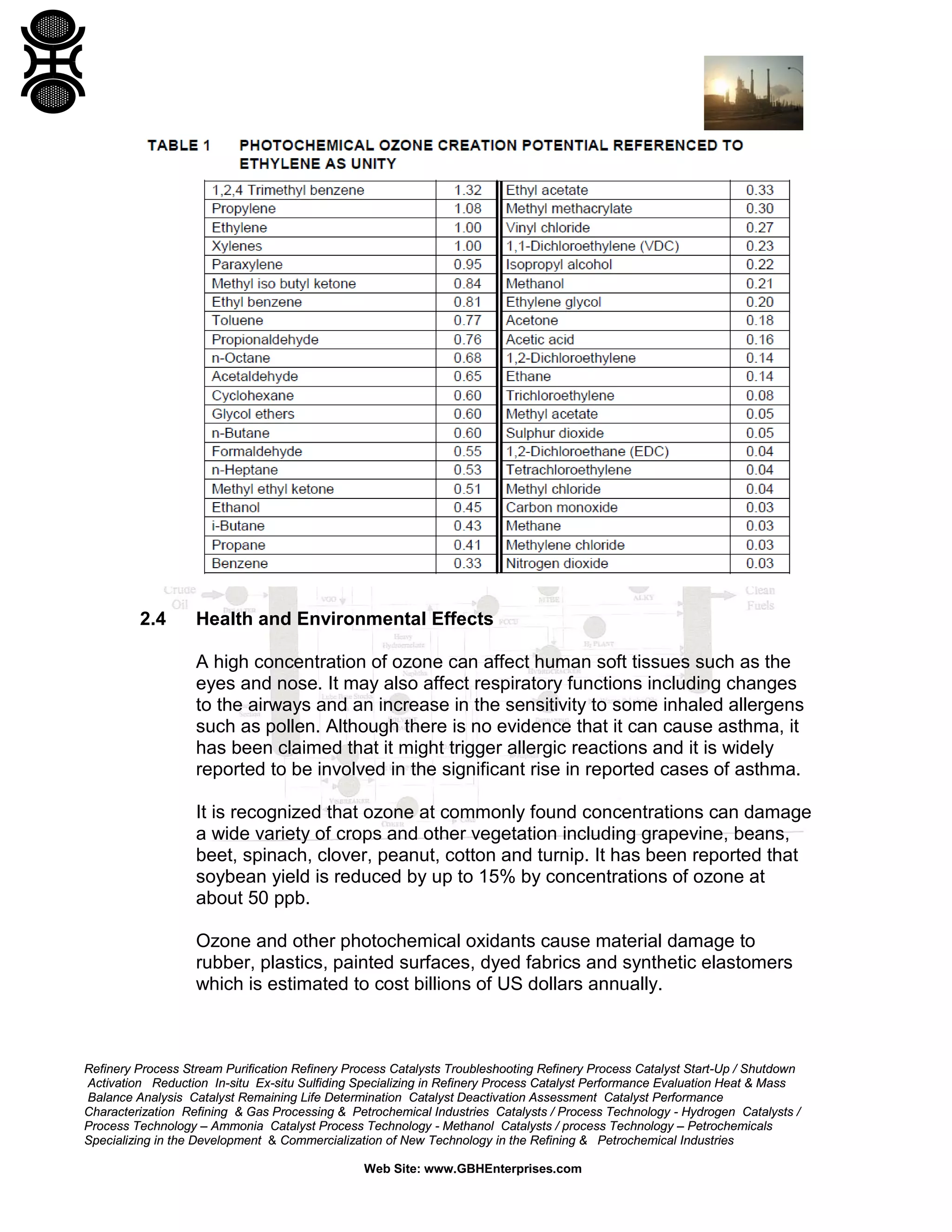
2.3 Photochemical Ozone Creation Potential
As stated above, VOCs and other substances can be classified according
to their POCP referenced to a standard of unity for ethylene [Ref. 5] as
shown in Table 1.](https://image.slidesharecdn.com/designventgascollectiondestructionsystems-150310004411-conversion-gate01/75/DESIGN-OF-VENT-GAS-COLLECTION-AND-DESTRUCTION-SYSTEMS-9-2048.jpg)
![Refinery Process Stream Purification Refinery Process Catalysts Troubleshooting Refinery Process Catalyst Start-Up / Shutdown
Activation Reduction In-situ Ex-situ Sulfiding Specializing in Refinery Process Catalyst Performance Evaluation Heat & Mass
Balance Analysis Catalyst Remaining Life Determination Catalyst Deactivation Assessment Catalyst Performance
Characterization Refining & Gas Processing & Petrochemical Industries Catalysts / Process Technology - Hydrogen Catalysts /
Process Technology – Ammonia Catalyst Process Technology - Methanol Catalysts / process Technology – Petrochemicals
Specializing in the Development & Commercialization of New Technology in the Refining & Petrochemical Industries
Web Site: www.GBHEnterprises.com
It is well known that smog in warm still air, such as regularly experienced
in the Los Angeles area, can be caused to some degree by photochemical
oxidants.
It is worthy of note that ozone is the only atmospheric pollutant that is
commonly present in concentrations that can be significant fractions of the
occupational exposure limit (OEL). Further information on the health and
environmental effects of ozone can be found in Refs. 4 and 5.
2.5 Air Quality Standards for Ground Level Concentrations of Ozone,
Targets for Reduction of VOC Discharges and Statutory Discharge
Limits
The World Health Organization guideline for ground level ozone
concentrations on an 8-hour average basis is 50-60 ppb. The National
Ambient Air Quality Standard for ozone in the USA is 120 ppb hourly
average, not to be exceeded on more than one day per year. The UK
Expert Panel on Air Quality Standards has proposed an Air Quality
Standard of 50 ppb as a running 8-hour average [Ref. 4]. The 8-hour time
weighted average (TWA) occupational exposure limit (OEL) for ozone is
100 ppb; the 3-minute TWA limit is 300 ppb.
A 1991 Protocol to the 1979 United Nations Economic Commission for
Europe (UNECE) Convention on Long Range Transboundary Air
Pollution, calls for voluntary reductions in VOC emissions across Europe
and North America by at least 30% by 1999 relative to 1988 levels.
There is increasing pressure from both legislative authorities and public
opinion to completely eliminate all vents containing VOCs.
In general, discharge limits for VOCs are set at national level and are
usually in the form of emission concentration limits. Some of these are
defined by statute as in TA Luft [Ref. 6] in Germany whereas others
appear as strict guidance limits as in IPR Guidance Notes [Ref. 7] in
the UK. Although the principles of POCP are becoming generally
accepted, it is likely to be some time before they are adopted formally by
the statutory control authorities.](https://image.slidesharecdn.com/designventgascollectiondestructionsystems-150310004411-conversion-gate01/75/DESIGN-OF-VENT-GAS-COLLECTION-AND-DESTRUCTION-SYSTEMS-11-2048.jpg)
![Refinery Process Stream Purification Refinery Process Catalysts Troubleshooting Refinery Process Catalyst Start-Up / Shutdown
Activation Reduction In-situ Ex-situ Sulfiding Specializing in Refinery Process Catalyst Performance Evaluation Heat & Mass
Balance Analysis Catalyst Remaining Life Determination Catalyst Deactivation Assessment Catalyst Performance
Characterization Refining & Gas Processing & Petrochemical Industries Catalysts / Process Technology - Hydrogen Catalysts /
Process Technology – Ammonia Catalyst Process Technology - Methanol Catalysts / process Technology – Petrochemicals
Specializing in the Development & Commercialization of New Technology in the Refining & Petrochemical Industries
Web Site: www.GBHEnterprises.com
The safety and environmental aspects of thermal oxidation are discussed
further in Section 6 of this guide.
4 METHODOLOGY FOR COLLECTION & ASSESSMENT OF PROCESS
FLOW DATA
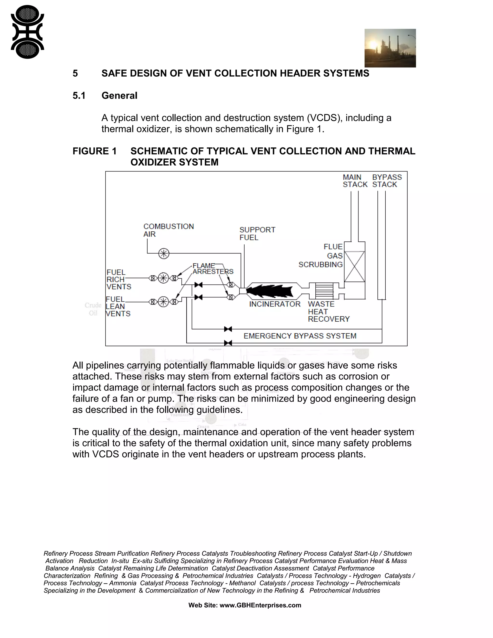
4.1 General
Vent gas collection and destruction systems are complex plants in their
own right. Hence, in order to ensure a safe design, a methodical approach
to the design basis and basis of safety is essential. This Section provides
a framework methodology which can be adapted to specific project
requirements.
Considerable effort is required to collect the information on flows,
compositions, component data, flammability data and scenarios which is
needed to produce the basis of safety for the system and the Hazard
Study. The use of a spreadsheet will assist in this process. This process is
especially difficult for batch plants where flows are intermittent and highly
variable.
For existing plants and processes it is essential to obtain the full co-operation of
the plant personnel in the information gathering process since they will have
experience of many of the possible deviations from normal operation which can
occur. It should be noted that some possible occurrences may never have been
experienced in the life of the plant due to their extremely low potential frequency.
The range of possible scenarios should be established by consultation with the
plant operations team and by examination of the Hazard Study records for the
project. If necessary, further Hazard Studies may be required to establish a
range of worst cases. Full transmittal of this information from the plant to the
project (or between members of the project team for new plants) is essential. For
new plants, all possible operating scenarios should be identified at the design
stage, again using information from the Hazard Study process. Other useful
techniques for hazard assessment and reduction are fault tree analysis, process
hazard review, failure mode and effect analysis and consequence analysis [Ref.
17].](https://image.slidesharecdn.com/designventgascollectiondestructionsystems-150310004411-conversion-gate01/75/DESIGN-OF-VENT-GAS-COLLECTION-AND-DESTRUCTION-SYSTEMS-16-2048.jpg)
![Refinery Process Stream Purification Refinery Process Catalysts Troubleshooting Refinery Process Catalyst Start-Up / Shutdown
Activation Reduction In-situ Ex-situ Sulfiding Specializing in Refinery Process Catalyst Performance Evaluation Heat & Mass
Balance Analysis Catalyst Remaining Life Determination Catalyst Deactivation Assessment Catalyst Performance
Characterization Refining & Gas Processing & Petrochemical Industries Catalysts / Process Technology - Hydrogen Catalysts /
Process Technology – Ammonia Catalyst Process Technology - Methanol Catalysts / process Technology – Petrochemicals
Specializing in the Development & Commercialization of New Technology in the Refining & Petrochemical Industries
Web Site: www.GBHEnterprises.com
Reasons for the choice of factor should be described in the basis of
safety. The amount of confidence in the accuracy of flow and composition
data should be considered when making the decision.
It should be noted that, whereas application of the NFPA standards is
mandatory in the US and Canada and may also be mandatory in some
other countries and is strongly recommended for use throughout the
Americas, it may not be accepted in others. It is necessary to check with
local regulatory authorities before making a final decision.
5.2.3.3 Inerting
Inert gas can be injected into the vent in order to reduce the concentration
of oxygen in the header to below the minimum oxygen concentration
(MOC) to sustain combustion. NFPA 69 suggests a limit of 60% of the
MOC with monitoring or 40% of the MOC if the MOC is below 5%. If not
continuously monitored, the oxygen concentration should be checked on a
regular basis (see NFPA 69). Again, the variability of the vent flow and
composition should be considered along with the measurement accuracy.
There may be circumstances where it is appropriate to use a larger safety
factor such as 25% of the MOC depending on the variability of vent flows,
process deviations and confidence in the data. The reasons for the
choice of dilution factor should be detailed in the basis of safety. As
above, it should be noted that application of the NFPA guides may be
mandatory in some countries.
5.2.3.4 Combination of Vent Headers
Combining vent streams should be considered very carefully. Although
mixing vent streams to ensure operation outside the flammable region is
possible, the various combinations of flow and composition should be
quantified in detail as deviations in one or other of the streams may result
in the header becoming flammable [Ref. 17]. This method of ensuring
operation outside the flammable region is not generally recommended
unless there is a high degree of certainty about vent flows, compositions
and equipment reliability.](https://image.slidesharecdn.com/designventgascollectiondestructionsystems-150310004411-conversion-gate01/75/DESIGN-OF-VENT-GAS-COLLECTION-AND-DESTRUCTION-SYSTEMS-37-2048.jpg)
![Refinery Process Stream Purification Refinery Process Catalysts Troubleshooting Refinery Process Catalyst Start-Up / Shutdown
Activation Reduction In-situ Ex-situ Sulfiding Specializing in Refinery Process Catalyst Performance Evaluation Heat & Mass
Balance Analysis Catalyst Remaining Life Determination Catalyst Deactivation Assessment Catalyst Performance
Characterization Refining & Gas Processing & Petrochemical Industries Catalysts / Process Technology - Hydrogen Catalysts /
Process Technology – Ammonia Catalyst Process Technology - Methanol Catalysts / process Technology – Petrochemicals
Specializing in the Development & Commercialization of New Technology in the Refining & Petrochemical Industries
Web Site: www.GBHEnterprises.com
The design of flame arresters is a complex subject. Only a short synopsis
of the main features is provided here. For further advice on design and
specification of flame arresters see the list of Best Contacts in Appendix B.
5.2.5.2 Types
The most common type of arrester in use is the conventional crimped
metal type (such as supplied by IMI Amal in the UK and Enardo in the
USA) but other types are available including flat or perforated plate and
liquid seal. Arresters are designed for a specific range of duties. An
arrester designed to cope with potential detonation will be designed to a
more stringent standard than one designed for deflagrations. There are a
number of standards applicable to testing of flame arresters including ISO,
BS, Canadian, Underwriters Laboratories [Ref. 14] and US Coast Guard
[Ref. 15]. The USCG tests are reckoned to be the most stringent. It should
be noted that suitable approval will be needed for flame arresters before
installation in the USA (Factory Mutual or Underwriters Laboratories) and
some other countries. Again, local authorities should be consulted.
Plate type arresters are less common in use than crimped metal types and
are limited to the less reactive gases and therefore are not suitable for
mixtures containing hydrogen or acetylene. This type is made by several
manufacturers, particularly in the USA, including Protectoseal and
Westech.
Liquid seal arresters are less common but are useful when dealing with
gases containing particulates or mists. There are no known published
design methods for this type; however, empirical design procedures have
been used in GBHE. Under conditions of high gas flow the seal may break
down and a gas path exist through the arrester. This type of arrester
should not be specified without reference to GBHE.
Pebble bed arresters are another example of a type which was used
extensively in the past but is little used today. Again there are no known
design criteria for this type of unit.](https://image.slidesharecdn.com/designventgascollectiondestructionsystems-150310004411-conversion-gate01/75/DESIGN-OF-VENT-GAS-COLLECTION-AND-DESTRUCTION-SYSTEMS-39-2048.jpg)
![Refinery Process Stream Purification Refinery Process Catalysts Troubleshooting Refinery Process Catalyst Start-Up / Shutdown
Activation Reduction In-situ Ex-situ Sulfiding Specializing in Refinery Process Catalyst Performance Evaluation Heat & Mass
Balance Analysis Catalyst Remaining Life Determination Catalyst Deactivation Assessment Catalyst Performance
Characterization Refining & Gas Processing & Petrochemical Industries Catalysts / Process Technology - Hydrogen Catalysts /
Process Technology – Ammonia Catalyst Process Technology - Methanol Catalysts / process Technology – Petrochemicals
Specializing in the Development & Commercialization of New Technology in the Refining & Petrochemical Industries
Web Site: www.GBHEnterprises.com
Therefore, wherever possible, peak flow rates of waste gas to be treated
should be attenuated and relief streams should not, as a general rule, be
fed to thermal oxidizer systems. Flare stacks may be used to cope with
high flow rates due to relief conditions but their destruction efficiency is
lower.
6.2.2 Destruction Efficiencies and Emission Limits
6.2.2.1 Destruction Efficiencies
The key design parameters for high efficiencies of destruction of organic
materials fed to thermal oxidizers are Temperature, Time, Turbulence
(often known as the 3 Ts) and oxygen concentration. A minimum
temperature of 850°C to 900°C is required to destroy most organics.
However, if halogenated materials are present, the statutory authorities
are likely to require a minimum temperature of 1100°C to 1200°C in order
to avoid the formation of halogenated dioxins and furans (see below).
It is generally accepted that the destruction of organics is so fast at
thermal oxidizer temperatures that reaction kinetics are not limiting.
However, minimum residence times of about 2 seconds after the last
injection point of combustion air are often required by statutory authorities
to ensure full and adequate mixing which is of paramount importance [Ref.
8]. The geometry of the combustion chamber and the orientation of the
main burner nozzle and air inlet ports are very important in order to ensure
high radial turbulence without any unmixed or cold spots. Residence time,
temperature and destruction efficiency will be specified on the permit to
operate in the US and Canada and a number of other countries.
A minimum oxygen concentration at the exit from the oxidizer of about 3%
v/v, without correction for water vapor, is generally required to ensure a
very high level of oxidation of organics. Monitoring of the excess oxygen in
the flue gas is mandatory in many countries to ensure complete
combustion.
Carbon monoxide (CO) is a good surrogate indicator of other products of
incomplete combustion (PICs) and, as such, it is customary to specify a
maximum limit of about 100 mg/m³ CO in the flue gas. This concentration
is often referenced to certain standard conditions, such as 1 atmos
pressure, 0°C, 11% v/v oxygen and dry gas in Europe. Also, the
period of time over which the concentration is averaged, such as 1 hour,
should be specified.](https://image.slidesharecdn.com/designventgascollectiondestructionsystems-150310004411-conversion-gate01/75/DESIGN-OF-VENT-GAS-COLLECTION-AND-DESTRUCTION-SYSTEMS-58-2048.jpg)
![Refinery Process Stream Purification Refinery Process Catalysts Troubleshooting Refinery Process Catalyst Start-Up / Shutdown
Activation Reduction In-situ Ex-situ Sulfiding Specializing in Refinery Process Catalyst Performance Evaluation Heat & Mass
Balance Analysis Catalyst Remaining Life Determination Catalyst Deactivation Assessment Catalyst Performance
Characterization Refining & Gas Processing & Petrochemical Industries Catalysts / Process Technology - Hydrogen Catalysts /
Process Technology – Ammonia Catalyst Process Technology - Methanol Catalysts / process Technology – Petrochemicals
Specializing in the Development & Commercialization of New Technology in the Refining & Petrochemical Industries
Web Site: www.GBHEnterprises.com
If nitrated organics are present in the incoming waste gas stream, a
proportion of the cooled flue gas can be recirculated back to the
combustion chambers for fuel-NOx control (see Section 6.3.3). Where
sulfur oxides are present, temperatures should again be high enough to
prevent the formation of sulfuric acid mist and associated corrosion.
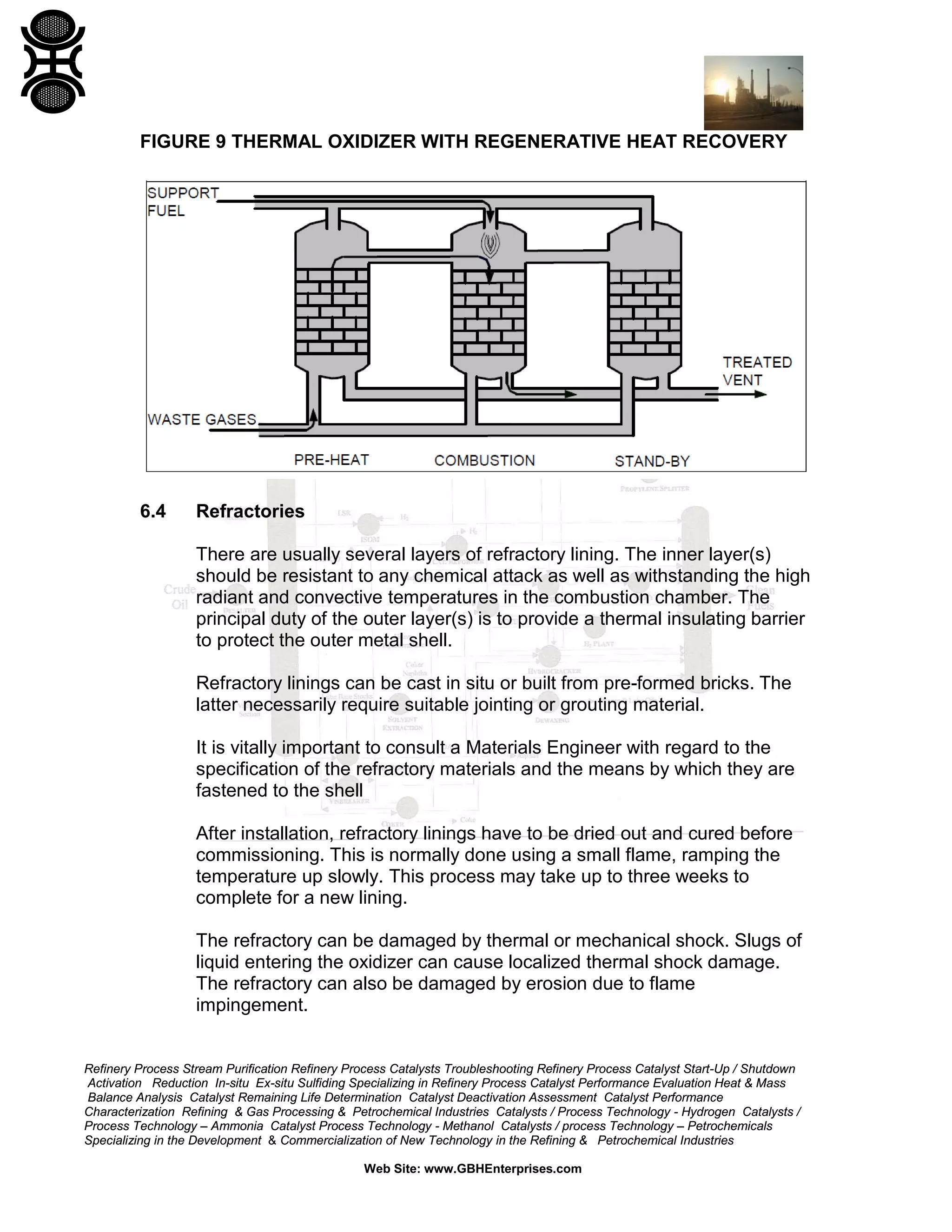
6.5.3.2 Regenerative Heat Recovery
A ceramic or brick matrix, pre-heated by direct contact with the hot flue
gas, can be used to pre-heat the incoming waste gas stream or
combustion air as illustrated in Section 6.3.6.
6.5.4 Plume Suppression
The UK Environment Agency may require steps to be taken to reduce the
size or frequency of a visible atmospheric dew point condensation plume
[Ref. 9].
Dew point condensation plume visibility increases with:
Increased temperature of flue gas that is saturated with water vapour;
Increased relative humidity and decreased temperature of the ambient
air.
As a general rule-of-thumb, dew point condensation plume visibility in
Europe should not be major issue if the flue gas relative humidity is
significantly below 100% or if its temperature is below about 40°C.
Dew point condensation plume visibility can be reduced by cooling to
condense out some of the water content, by heating the flue gas or by
diluting it with air. The most common approach is to dilute with hot air. As
a general rule-of-thumb, diluting hot flue gas that is saturated with water
vapor at about 70°C with an equal amount of hot air to achieve a
mixed gas temperature of about 110°C will avoid plume visibility issues in
Europe.](https://image.slidesharecdn.com/designventgascollectiondestructionsystems-150310004411-conversion-gate01/75/DESIGN-OF-VENT-GAS-COLLECTION-AND-DESTRUCTION-SYSTEMS-72-2048.jpg)
![Refinery Process Stream Purification Refinery Process Catalysts Troubleshooting Refinery Process Catalyst Start-Up / Shutdown
Activation Reduction In-situ Ex-situ Sulfiding Specializing in Refinery Process Catalyst Performance Evaluation Heat & Mass
Balance Analysis Catalyst Remaining Life Determination Catalyst Deactivation Assessment Catalyst Performance
Characterization Refining & Gas Processing & Petrochemical Industries Catalysts / Process Technology - Hydrogen Catalysts /
Process Technology – Ammonia Catalyst Process Technology - Methanol Catalysts / process Technology – Petrochemicals
Specializing in the Development & Commercialization of New Technology in the Refining & Petrochemical Industries
Web Site: www.GBHEnterprises.com
6.6 Control and Safety Systems
6.6.1 Control System (Burner Management System)
One of the principal challenges for the design and operation of vent gas
collection and thermal systems is that of control. Most of the problems that
are experienced with these systems result from the variable flow rate and
composition of the gaseous feed streams. It is generally not possible to
measure these variables for use in a feed forward control system.
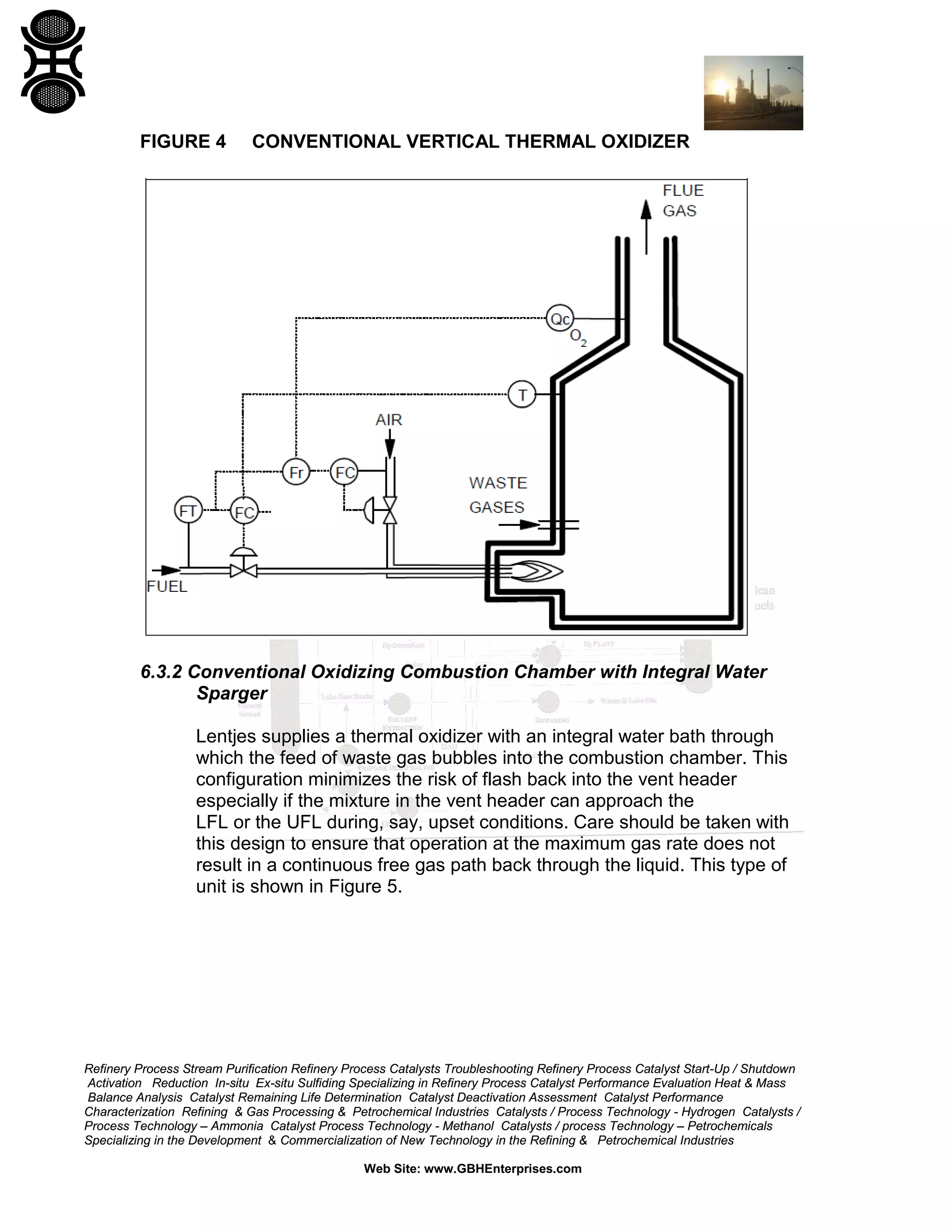
Consequently, most control systems rely on feedback of the combustion
chamber temperature and flue gas composition as shown in the simplified
diagram in Figure 4. Sometimes it is appropriate, as in the case of staged
air combustion (see Section 6.3.3), to use temperature difference across a
combustion chamber as one of the measured control parameters. It
should be noted that in some parts of the USA, analysis of the excess
oxygen in the flue gas is mandatory. A burner management design guide
has been produced [Ref. 10] which gives advice on design and
specification of thermal oxidizer control systems. Design of control
systems in North America is governed by NFPA 86. In Canada, fuel gas
trains should conform to the Canadian Gas Association Code and oil
burner trains to NFPA 86. Also in Canada, only approved fittings may be
used, therefore the use of local engineering contractors is strongly
recommended. Advice on control systems should be sought from the
corporate insurer who is the "Authority with Jurisdiction" referred to in the
NFPA codes.
As feedback control is typical, it is important to study the process and
control dynamics of the system and to ensure that, for example, rates of
change of flow rate or composition of the incoming waste gases can be
accommodated safely.
It may be appropriate, in some cases, to install a relatively simple control
system and use, for example, larger than normal amounts of excess
support fuel and combustion air.
Dynamic simulation may be used to model the operation of the control
system. For advice on this topic see list of Best Contacts in Appendix B.
Burner management systems may be complex, with large numbers of
inputs and outputs. All control systems should be thoroughly tested at the
factory as it may be difficult to carry out simulations of control conditions
on site.](https://image.slidesharecdn.com/designventgascollectiondestructionsystems-150310004411-conversion-gate01/75/DESIGN-OF-VENT-GAS-COLLECTION-AND-DESTRUCTION-SYSTEMS-73-2048.jpg)
![Refinery Process Stream Purification Refinery Process Catalysts Troubleshooting Refinery Process Catalyst Start-Up / Shutdown
Activation Reduction In-situ Ex-situ Sulfiding Specializing in Refinery Process Catalyst Performance Evaluation Heat & Mass
Balance Analysis Catalyst Remaining Life Determination Catalyst Deactivation Assessment Catalyst Performance
Characterization Refining & Gas Processing & Petrochemical Industries Catalysts / Process Technology - Hydrogen Catalysts /
Process Technology – Ammonia Catalyst Process Technology - Methanol Catalysts / process Technology – Petrochemicals
Specializing in the Development & Commercialization of New Technology in the Refining & Petrochemical Industries
Web Site: www.GBHEnterprises.com
Bring on the vent gas flow at low rate to oxidizer;
Ramp up the vent gas flows to normal operating conditions and shut
off flows to diversion system.
The failure to establish any step successfully should abort the start-up and
initiate a purge of the burner chamber. It should be noted that after the fuel
to the thermal oxidizer has been shut off, the refractory material may
remain hot for a long period. If the VOC vent flow or support fuel is re-
introduced during this period, then an explosion may result due to delayed
ignition from the hot refractory. A hot restart should not, therefore, be
attempted if the temperature of the refractory is above the AIT unless the
burner management system is specifically designed to cope with hot
restarts. The burner management system should have provision for hot
restart unless there are exceptional circumstances which would make this
event hazardous.
Factory Mutual 6-11 [Ref. 13] states that there should be a mandatory pre-
ventilation period to purge the combustion chamber, intake and exhaust
systems of any fumes or fuel which may have accumulated during
shutdown periods. It should be noted that in the US and Canada the start-
up and shut-down sequences should be handled by the BMS as described
above. This is also strongly recommended for installations in other
countries. The purge should be proven by suitable interlocks or monitoring
instruments. At least three volume changes of air are required by Factory
Mutual 6-11 and the period should be timer controlled to prevent
actuation of fuel valves or ignition devices during the purge. Dampers
should be set to the open position during the purge and, if necessary,
provided with interlocks or indicators to prove them open.
The pilot flame is established using small flows of natural gas (or fuel gas)
and air. The flow of gas to the pilot flame is small enough that it would
take a significant time to fill the combustion chamber with sufficient
quantity of unburned gas to cause damage to the chamber shell in the
event of a delayed ignition. Factory Mutual 6-11 [Ref. 13] states that
interlocks should be provided on fuel supply pressure (high and low as
required) and also atomizing air or steam pressure where used. NFPA
85C also contains recommendations on purging and fuel shut off.
The pilot flame is usually turned off after the main flame has been
established. This minimizes erosion of the spark ignition electrodes and
wear and tear on the pilot burner itself. Operation of the pilot and ignition
system can normally be checked with the thermal oxidizer on-line.](https://image.slidesharecdn.com/designventgascollectiondestructionsystems-150310004411-conversion-gate01/75/DESIGN-OF-VENT-GAS-COLLECTION-AND-DESTRUCTION-SYSTEMS-77-2048.jpg)


This document provides a comprehensive guide on the safe design of vent gas collection and destruction systems, particularly focusing on thermal oxidizers for the treatment of volatile organic compounds (VOCs) in refining and petrochemical industries. It covers environmental considerations, system design methodologies, and emphasizes the importance of integrating safety measures and regulatory compliance throughout the design process. Additionally, it outlines the potential health and environmental impacts of ozone and VOCs, alongside guidelines for their effective management.


