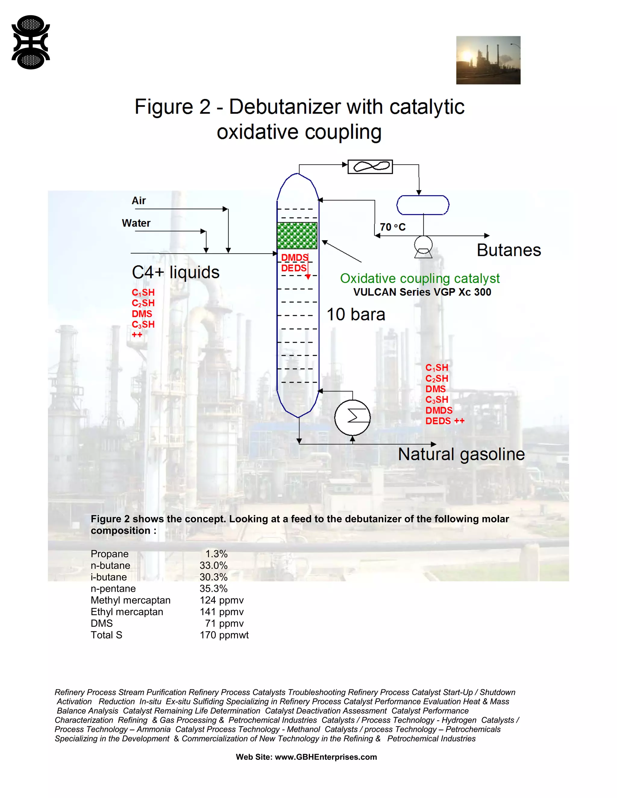
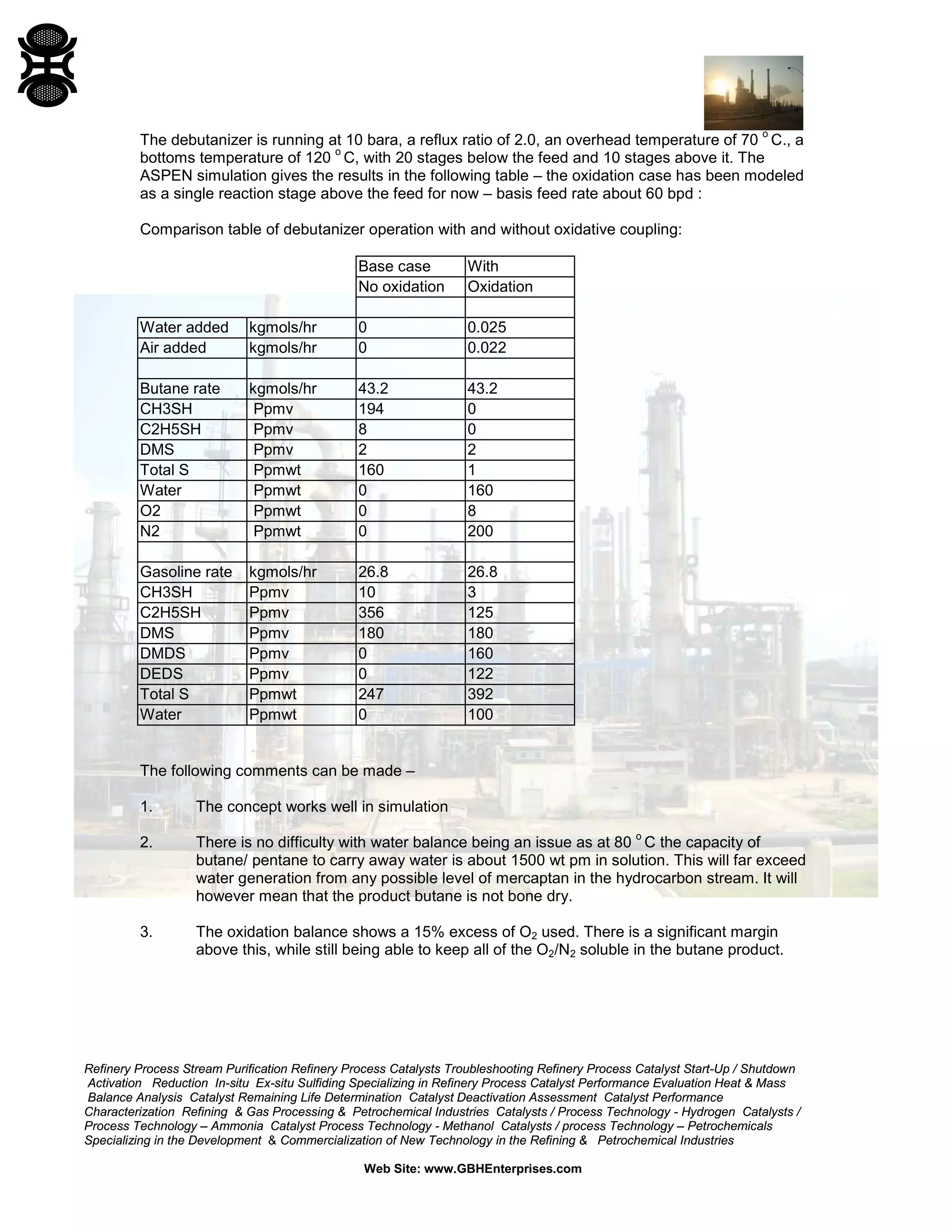
Tools for Reactor Modeling:
THE ELEMENT POTENTIAL METHOD FOR CHEMICAL EQUILIBRIUM ANALYSIS: STANJAN
CONTENTS
1 SCOPE
2 SUMMARY
3 INTRODUCTION
4 EXAMPLES
4.1 CARBON-RICH C-0 SYSTEM
4.2 EXAMPLE WITH TWO COMPLEX PHASES
4.3 GAS TURBINE ENGINE EXAMPLE
4.4 OTHER APPLICATIONS
APPENDIX
FIGURES
5.1 EXAMPLE RUN LOG FOR CARBON-RICH C-O SYSTEM
5.2 OUTPUT FOR EXAMPLE WITH TWO COMPLEX PHASES
5.3 FIRST STEP IN THE TURBINE EXAMPLE: CALCULATION OF THE ENTHALPY OF THE REACTANTS
5.4 SECOND STEP IN THE TURBINE EXAMPLE: CALCULATION OF THE ADIABATIC FLAME TEMPERATURE
5.5 THIRD STEP IN THE TURBINE EXAMPLE: CALCULATION OF THE NOZZLE EXIT STATE
AVAILABILITY AND IMPLEMENTATION OF STANJAN
REFERENCES
Debottlenecking Claus Sulfur Recovery Units: An Investigation of the applicat...Gerard B. Hawkins
Debottlenecking Claus Sulfur Recovery Units: An Investigation of the application of Zinc Titanates
1 Executive Summary
2 Claus Process
2.1 Partial Combustion Claus
2.2 Split Flow Claus
2.3 Sulfur Recycle Claus
3 Zinc Titanates
4 Application of Zinc Titanate to Debottleneck Partial Combustion Claus by 10%
4.1 Process
4.2 ASPEN Modeling Results
4.3 Cost of Zinc Titanate Bed Installation
4.3.1 Basis of Costing
4.3.2 Zinc Titanate Beds
4.3.3 Regen Cooler
4.3.4 Blowers
4.3.5 Results
4.4 Alternative Debottlenecking Technology for Partial Combustion Claus
4.5 Cost of 10% Debottlenecking Using COPE Process
5 Debottlenecking Claus Split Flow System by 10% with Zinc Titanates
6 Debottlenecking Claus Sulfur Recycle System With Zinc Titanate
7 Effect of Zinc Titanate Debottlenecking on Existing Tail; Gas Treatment Systems
7.1 Selectox
7.2 SuperClaus99
7.3 Superclaus 99.5
7.4 SCOT Process
7.5 Zinc Titanate as a Claus Tail Gas Treatment
7.6 H2S Removal Efficiency With Zinc Titanate
8 Effects on COS and CS2 Formation
9 Questions for further Investigation
FIGURES
Figure 1 Claus Unit and TGCU
Figure 2 Claus Process
Figure 3 Typical Claus Sulfur Recovery Unit
Figure 4 Two-Stage Claus SRU
Figure 5 The Super Claus Process
Figure 6 SCOT
Figure 7 SCOT/BSR-MDEA (or clone) TGCU
REFERENCES: PATENTS
US4333855_PROMOTED_ZINC_TITANATE_CATALYTIC_AGENT
US4394297_ZINC_TITANATE_CATALYST
US6338794B1_DESULFURIZATION_ZINC_TITANATE_SORBENTS
SMR PRE-REFORMER DESIGN
Case Study #0618416GB/H
Contents
1. SMR Pre-Reformer Design
2. Inlet Baffle Design
3. Outlet Collector
4. Hold Down Grating
5. Floating Hold Down Screen
6. Catalyst Drop Out Nozzle
7. Thermowell Detail
8. Technical Performance requirements
9. SMR Pre-Reformer Isolation
Technical Review and Commentary on Proposed Design
APPENDIX
A. Operating / Mechanical Data
B. Materials Specifications
C. Fabrication and Inspection Requirements
D. Weights
E. Nozzle Data
F. Instrument Connections
G. Manholes
Determination of Argon in Ammonia Plant Process Gas Streams by Gas Chromatogr...Gerard B. Hawkins
Determination of Argon in Ammonia Plant Process Gas Streams by Gas Chromatography
SCOPE AND FIELD OF APPLICATION
This document is a method for the determination of argon in process gas streams in the range 0-10% v/v.
This Engineering Design Guide has several aims.
It is intended to take an experienced mechanical engineer through the steps necessary to specify a gear and to carry out an assessment of gears offered against a particular specification for pumps, fans and compressors driven by electric motors, steam turbines, combustion gas turbines or expanders. It is not part of this Engineering Design Guide to show how to decide that a gear is or is not necessary for a particular duty.
High Temperature Shift Catalyst Reduction ProcedureGerard B. Hawkins
High Temperature Shift Catalyst Reduction Procedure
The catalyst, as supplied, is Fe2O3. This reduces to the active form, Fe3O4, in the presence of hydrogen when process gas is admitted to the reactor.
1. The mildly exothermic reactions are:
3 Fe2O3 + H2 ========= 2 Fe3O4 + H2O
3 Fe2O3 + CO ========= 2 Fe3O4 + CO2
The Selective Oxidation of n-Butane to Maleic Anhydride in a Catalyst Packed ...Gerard B. Hawkins
The Selective Oxidation of n-Butane to Maleic Anhydride in a Catalyst Packed Tubular Reactor
CONTENTS
0 INTRODUCTION
1 n-BUTANE OXIDATION
2 REACTION KINETICS
3 HEAT AND MASS TRANSFER PARAMETERS
4 NON-ISOTHERMAL, NON-ADIABATIC REACTOR MODELING
5 USE OF THE REACTOR MODEL IN OPERABILITY AND DESIGN STUDIES
6 BIBLIOGRAPHY
7 NOMENCLATURE
DEACTIVATION OF METHANOL SYNTHESIS CATALYSTS
CONTENTS
1 INTRODUCTION
2 THERMAL SINTERING
3 CATALYST POISONING
4 REACTANT INDUCED DEACTIVATION
5 SUMMARY
TABLES
1 DEACTIVATION PROCESSES ON METHANOL SYNTHESIS CATALYSTS
2 MELTING POINT, HUTTIG AND TAMMANN TEMPERATURES OF COPPER, IRON AND NICKEL
3 SINTERING RATE CONSTANTS CALCULATED INLET AND OUTLET SIDE STREAM UNIT FOR VULCAN VSG-M101
4 COMPARISON BETWEEN CALCULATED S∞ AND DISCHARGED MEASUREMENTS ON VULCAN VSG-M101
5 EFFECT OF POSSIBLE CONTAMINANTS AND POISONS ON CU/ZNO/AL2O3 CATALYSTS FOR METHANOL SYNTHESIS
6 GUARD SCREENING TEST RESULTS ON METHANOL MICRO-REACTOR. EFFECT OF DEPOSITED METALS ON METHANOL ACTIVITY
FIGURES
1 THE HΫTTIG AND TAMMANN TEMPERATURES OF THE COMPONENTS OF A SYNTHESIS CATALYST
2 A SCHEMATIC REPRESENTATION OF TWO CATALYST SINTERING MECHANISMS
3 SIDE STREAM DATA FOR VULCAN VSG-M101. INLET TEMPERATURE 242 OC, PRESSURE 1500 PSI, GAS COMPOSITION 6% CO, 9.2% CO2, 66.9% H2, 2.5% N2 AND 15.4% CH4, SPACE VELOCITY 17,778 HR-1. MEAN OUTLET TEMPERATURE 280 OC
4 TEMPERATURE DEPENDENCE OF THE RATE OF SINTERING
5 MECHANISM OF SULFUR RETENTION
6 CORRELATION OF SULFUR CAPACITY WITH TOTAL SURFACE AREA
7 EFFECT OF DEPOSITED (NI+FE) PPM ON METHANOL SYNTHESIS CATALYST ACTIVITY
8 DISCHARGED (FE + NI) DEPOSITION LEVELS ON METHANOL SYNTHESIS PLANT SAMPLES
9 EPMA ANALYSIS OF DISCHARGED LABORATORY SAMPLE OF POISONED VULCAN VSG-M101
10 THE EFFECT OF CO2 ON SYNTHESIS CATALYST DEACTIVATION
REFERENCES
Chemical Process Conception
0 INTRODUCTION / PURPOSE
1 SCOPE
2 FIELD OF APPLICATION
3 DEFINITIONS
4 PRODUCT STRATEGY
4.1 General
4.2 Market for the Product
4.3 Production Costs
4.4 Process Technology
5 PRELIMINARY PROCESS INFORMATION
6 REACTION AND REACTOR
6.1 Batch vs Continuous
6.2 Multiple Reactors
7 RECYCLE
7.1 Recycle Structure
7.2 Classification of Chemicals
7.3 Effect of Recycle
7.4 Preliminary Estimation of Conversion
8 REACTOR TYPE AND PERFORMANCE
8.1 Conversion-Yield Effects
8.2 Heat Effects
8.3 Equilibrium Effects
8.4 Kinetic Effects
8.5 More Help with Reactor Design
9 SEPARATION SYSTEM
10 REVIEW
11 BIBLIOGRAPHY AND REFERENCES
11.1 Preliminary Flowsheeting
11.2 Physical Properties
11.3 Reactors
11.4 Separation
11.5 Costing
APPENDICES
A BASIC REACTOR SYSTEM DESIGN
B DISCUSSION BETWEEN A CHEMIST AND A
CHEMICAL ENGINEER
C BASIC SEPARATION STRATEGY
TABLES
1 CLASSIFICATION OF MATERIALS
FIGURES
1 FLOWCHART OF THE ITERATIVE PROCEDURE REQUIRED IN PROCESS AND PRODUCT SELECTION AND DEVELOPMENT
Determination of Oxygen in Anhydrous Ammonia
SCOPE AND FIELD OF APPLICATION
This method is suitable for the determination of trace amounts of oxygen in Liquefied anhydrous ammonia.
The trace oxygen analyzer provides for trace oxygen analysis in decade steps ranging from 0 - 10 to 0 - 10,000 ppm v/v (full scale).
Carbon Formation in Mixed Feed Preheat Coils:
Maximum Mixed Feed Pre-heat Temperature
What follows is a crude but effective routine, which evaluates the maximum possible temperature allowable to prevent excessive carbon laydown in the mixed feed pre-heat coils.
TEMPERATURE MEASUREMENT:
RESISTANCE ELEMENTS AND THERMOCOUPLES
SPECIFICATION OF FUNCTION
DESCRIPTION OF FLUID
NORMAL OPERATING TEMPERATURE
REQUIRED TEMPERATURE RANGE
ALARM SETTINGS
TRIP SETTINGS
FLUID VELOCITY
REYNOLDS NUMBER
LINE SIZE
LINE REFERENCE
EQUIPMENT REFERENCE
NOZZLE SIZE
MINIMUM DESIGN PRESSURE
CORRESPONDING TEMPERATURE
MAXIMUM DESIGN PRESSURE
CORRESPONDING TEMPERATURE
Determination of Hydrocarbons in Anhydrous Ammonia By Gas ChromatographyGerard B. Hawkins
Determination of Hydrocarbons in Anhydrous Ammonia By Gas Chromatography
SCOPE AND FIELD OF APPLICATION
The method is suitable for the determination of hydrocarbons from C1 to C4 (see 6.4.2) in gaseous ammonia, or in mixtures of ammonia and air. It is valid for concentrations in the range 10-10000 ppm.
The method may be used for the analysis of the atmosphere from a ships hold After purging with ammonia and for the analysis of gasified liquid anhydrous ammonia during or after loading. In these cases, hydrocarbon contamination may arise from the previous cargo of the vessel, the nature of which should be ascertained prior to carrying out the analysis
"SEDIMENTATION"
INTRODUCTION - THE PHENOMENON OF SEDIMENTATION
Sedimentation is the physical process whereby solid particles, of greater density than their suspending medium, will tend to separate into regions of higher concentration under the influence of gravity. As a solids/liquids separation technique it therefore possesses the great advantage of utilizing a natural, and therefore costless, driving force. This section of the suspension processing Guide is Intended to provide an Introduction to the science of the subject, and the means to judge where and how best to exploit sedimentation as a separation (or other processing) technique.
As a scientific discipline the subject of sedimentation is vast with perspectives ranging from the field of chemical engineering through to theoretical physics being covered In the literature [1-11]. Good reviews of the subject, with a bias towards the engineering aspects, have been written by Fitch and Koz [12, 13]. A short summary of some of the more relevant contributions from the literature is also provided in GBHE-SPG-PEG-302 “Basic Principles & Test Methods”, of the Suspensions Processing Guides.
.
The sedimentation process is traditionally divided into ..."
Gas - Liquid Reactors
0 INTRODUCTION/PURPOSE
1 SCOPE
2 FIELD OF APPLICATION
3 DEFINITIONS
4 PRELIMINARY CONSIDERATIONS
4.1 Preliminary Equipment Selection
4.2 Equipment for Low Viscosity Liquids
4.3 Equipment for High Viscosity Liquids
5 REACTOR DESIGN
6 ESSENTIAL THEORY
6.1 Rate and Yield Determining Steps
6.2 Chemical and Physical Rates
6.3 Modification for Exothermic and Complex Reactions
6.4 Preliminary Selection of Reactor Type
7 EXPERIMENTAL DETERMINATION OF REGIME
7.1 Direct Measurement of Reaction Kinetics
7.2 Laboratory Gas-Liquid Reactor Experiments
8 EQUILIBRIUM AND DIFFUSIVITY DATA SOURCES
9 OVERALL EFFECTS
9.1 Liquid Flow Patterns
9.2 Scale of Mixing
9.3 Gas Flow Pattern : Mean Driving Force for Mass Transfer
9.4 Gas-Liquid Reactor Modeling
9.5 Heat Transfer
9.6 Materials of Construction
9.7 Foaming
10 FINAL CHOICE OF REACTOR TYPE
11 SCALE-UP AND SPECIFICATION OF GAS-LIQUID
REACTORS
11.1 Bubble Columns
11.2 Packed Columns
11.3 Trickle Beds
11.4 Plate or Tray Columns
11.5 Spray Columns
11.6 Wiped Film
11.7 Spinning Film Reactors
11.8 Stirred Vessels
11.9 Plunging Jet
11.10 Surface Aerator
11.11 Static Mixers
11.12 Ejectors, Venturis and Orifice Plates
11.13 3-Phase Fluidized Bed
12 BIBLIOGRAPHY
TABLES
1 REGIMES OF GAS-LIQUID MASS TRANSFER WITH ISOTHERMAL CHEMICAL REACTION
2 REGIMES OF GAS-LIQUID MASS TRANSFER IGNORING LARGE EXOTHERMS OR OTHER COMPLICATIONS
3 COMPARATIVE MASS TRANSFER PERFORMANCE OF CONTACTING DEVICES
4 COMPARATIVE MASS TRANSFER DATA
5 CHOICE OF GAS-LIQUID REACTOR TYPE
FIGURES
1 RATE AND YIELD DETERMINING STEPS
2 ENHANCEMENT FACTOR vs HATTA NUMBER
3 ENHANCEMENT FACTOR vs HATTA NUMBER : EFFECT OF THERMAL & OTHER FACTORS
4 REACTORS FOR LIQUID-PHASE KINETICS
MEASUREMENT
5 EXPERIMENTS TO DETERMINE THE OPERATING
REGIME
6 EXPERIMENTS DETERMINE THE OPERATING REGIME WHERE A SOLID CATALYST IS INVOLVED
7 THE MIXED ZONES IN LOOPS' MODEL FOR STIRRED REACTORS
Avoiding Stress Corrosion Cracking of Carbon Low Alloy and Austenitic Stainl...Gerard B. Hawkins
Avoiding Stress Corrosion Cracking of Carbon Low Alloy and Austenitic Stainless Steels in Chloride and Caustic Environments
SYNOPSIS
This Maintenance Best Practice Guide is concerned with the performance of carbon and low alloy steels, and austenitic stainless steels, in chloride and caustic containing fluids. Those factors which are known to promote stress corrosion cracking are outlined, and service charts defining environmental boundaries for stress corrosion cracking in caustic and chloride containing fluids are presented.
General guidance on the avoidance of stress corrosion cracking is provided.
Fundamentals of Suspensions & Dispersion's
0 INTRODUCTION
1 NATURE OF SURFACE FORCES
2 STABILITY AND THE STATE OF DISPERSION OF
SUSPENDED PARTICLES
3 MECHANISMS OF FLOCCULATION
4 STRUCTURE OF FLOCCULATED SUSPENSIONS
4.1 Dilute Suspensions
4.2 Concentrated Suspensions
5 STRUCTURE OF STABLE SUSPENSIONS OF
MONODISPERSE PARTICULATES
6 SUMMARY OF STRUCTURES
7 PARTICLE PACKING
8 RHEOLOGY
8.1 Basic Rheological Concepts
8.2 Colloidally Stable Suspensions
8.2.1 Spherical Particles of around 1 µm
8.2.2 Effect of Particle Size Distribution
8.2.3 Effect of Particle Shape
8.2.4 Submicron Particles
8.2.5 Very Concentrated Systems
8.3 Rheology of Flocculated / Aggregated Systems
8.3.1 Dilute Flocculated Systems
8.3.2 Concentrated Flocculated Systems
8.3.3 Time and History Effects
8.3.4 Slip and Fracture
8.3.5 Behavior of Flocculated Cakes in Compression
8.4 Summary of Rheology
Deflocculated Suspensions
Flocculated Suspensions
9 SEDIMENTATION OF SMALL PARTICLES
9.1 Very Dilute Particles
9.2 Concentrated Systems
9.3 Polydisperse Systems
9.4 Flocculated Systems
10 ELECTROKINETIC BEHAVIOR
11 A NOTE ON MAKING DISPERSIONS AND SUSPENSIONS
12 References
13 Figures
Fig 1a Potential Energy Diagram for Steric Stabilization
Fig 1b PE Diagram for Electrostatic Stabilization
Fig 1c Combined Stabilization
Fig 2&3 DIFFERENT TYPES OF FLOCCULATION MECHANISM IN WHICH POLYMERIC SPECIES ARE INVOLVED
Fig 4 Rheological Behavior
Fig 5 Relative Viscosity versus Volume Fraction for Polystyrene Spheres in Water
Fig 6 Time Dependent Flow Behavior of Very Concentrated Suspensions
Fig 7 Flow curves for Flocculated Dispersions
Reactor and Catalyst Design
0 INTRODUCTION/PURPOSE
1 SCOPE
2 FIELD OF APPLICATION
3 DEFINITIONS
4 CATALYST DESIGN
4.1 Equivalent Pellet Diameter
4.2 Voidage
4.3 Pellet Density
5 REACTOR DESIGN
6 CATALYST SUPPORT
6.1 Choice of Support
TABLES
1 CATALYST SUPPORT SHAPES
2 SECONDARY REFORMER SPREADSHEET
FIGURES
1 GRAPH OF EFFECTIVENESS v THIELE MODULUS
2 VARIATION OF COSTS WITH CATALYST SIZE
3 VARIATION OF COSTS WITH CATALYST BED VOIDAGE
4 VARIATION OF COSTS WITH VESSEL DIAMETER
METHANOL PLANT - SHALE GAS FEED PRETREATMENT
CASE STUDY #091406
Case Background
A Methanol plant operator would like to examine the technical feasibility of using Shale Gas as a feedstock to their Methanol plant.
The first step in the Methanol production process is gas pretreatment. The purpose of gas pretreatment is to make the gas suitable for the downstream processes. There are two groups of compounds that are usually present in natural gas and that should be removed during pretreatment—the associate NGL and the sulfur-containing compounds. Some natural gas reservoirs may also have other trace components that must be removed, but these are not discussed here.
This case study examines the impact of CO2 (Carbon Dioxide) on the pre-treatment section design, performance and efficiency of ACME Methanol Plant’ feed gas pre-treatment section.
Case 1: Normal Shale Gas
Case 2: “Bad Gas”
Case 3: Low CO2
Case 4: High CO2
Reactor Arrangement for Continuous Vapor Phase ChlorinationGerard B. Hawkins
Reactor Arrangement for Continuous Vapor Phase Chlorination
CONTENTS
1 BACKGROUND
2 REACTOR
3 CHEMICAL SYSTEM
4 PROCESS CHEMISTRY
5 KINETICS EXPERIMENTS AND MODELING
6 INTERPRETATION OF KINETICS INFORMATION
7 OPERATING CONDITIONS AND REACTOR DESIGN
8 REACTOR STABILITY AND CONTROL
FIGURES
1 POSTULATED REACTION PATHS FOR PROGRESSIVE CHLORINATION OF B-PICOLINE 3
2 CHLORINATION OF b-PICOLINE: MODEL PREDICTIONS OF PRODUCT DISTRIBUTION IN FULLY-MIXED REACTOR
3 TWO-STAGE REACTOR: RATE OF CHLORINATION OF b-PICOLINE
DOCUMENTS REFERRED TO IN THIS PROCESS ENGINEERING GUIDE
Distillation Sequences, Complex Columns and Heat IntegrationGerard B. Hawkins
Distillation Sequences, Complex Columns and Heat Integration
0 INTRODUCTION/PURPOSE
1 SCOPE
2 FIELD OF APPLICATION
3 DEFINITIONS
4 SEQUENCING OF SIMPLE COLUMNS
4.1 Sidestream Columns
4.2 Multi-Feed Columns
5 SIMPLE COLUMN SEQUENCING AND HEAT
INTEGRATION INTERACTIONS
5.1 Energy Quantity and Quality
5.2 Heat Integration within the Total Flowsheet
6 COMPLEX COLUMN ARRANGEMENTS
6.1 Indirect Sequence with Vapor Link
6.2 Sidestream Systems
6.3 Pre-Fractionator Systems
7 COMPLEX COLUMNS AND HEAT INTEGRATION
INTERACTIONS
FIGURES
1 DIRECT AND INDIRECT SEQUENCES
2 A SINGLE SIDESTREAM COLUMN REPLACING 2
SIMPLE COLUMNS
3 A TYPICAL MULTI-FEED COLUMN
4 TYPICAL GRAND COMPOSITION CURVE
5 TYPICAL INDIRECT SEQUENCE WITH VAPOUR LINK
6 SIDESTREAM STRIPPER AND SIDESTREAM
RECTIFIER
7 SIMPLEST PRE-FRACTIONATOR SYSTEM
8 SIMPLEST PRE-FRACTIONATOR SYSTEM
9 PETLYUK COLUMN
Residence Time Distribution Data
0 INTRODUCTION/PURPOSE
1 SCOPE
2 FIELD OF APPLICATION
3 DEFINITIONS
4 BASICS OF RESIDENCE TIME DISTRIBUTION DATA
5 USE OF RESIDENCE TIME DISTRIBUTION DATA
5.1 Micromixing and Macromixing
5.2 Example 1 - Reaction is First Order
5.3 Example 2 - Reaction is Second Order
5.4 Complex Reactions and Residence Time Distribution
5.5 Examples
6 RESIDENCE TIME MEASUREMENTS WITH
RADIOISOTOPES
6.1 General
6.2 Types of Reactors
6.3 Models Based on Method of Moments
6.4 Non-impulse Input
6.5 Diagnosis of Problems
6.6 Commercial Radioisotope Service
7 BIBLIOGRAPHY
Process Synthesis
INTRODUCTION
1 A SUGGESTED GENERAL APPROACH
2 EXAMPLES OF PROCESS SELECTION
2.1 Harvesting and Thickening of Single Cell Protein
2.2 Dewatering of a Specialty Latex
3 REFERENCES
TABLES
1 THE ADVANTAGES AND DISADVANTAGES OF DIFFERENT RANGE OF PH FOR “PROTEIN” ORGANISM FLOCCULATION
2 THE ADVANTAGES AND DISADVANTAGES OF VARYING EXTENTS OF CELL BREAKAGES
3 PREDICTED AND OBSERVED FILTER CAKE SOLIDS CONTENTS FOR THE VARIOUS LATICES AFTER COAGULATION
FIGURES
1 THE “PROTEIN” BACTERIAL HARVESTING SYSTEM
2 PROCESS FOR MANUFACTURE OF CALCIUM CARBONATE FILTERS
3 H-ACID ISOLATION
4 A SUGGESTED APPROACH TO DETERMINING FEASIBLE PROCESS OPTIONS, AND OPERATING CONDITIONS FOR SEPARATION OF FINE SOLIDS FROM SUSPENSION
5 MODULI VERSUS SOLIDS CONTENT FORTYPICAL FORWARD FLOCCULATED “PROTEIN” SUSPENSIONS
6 DECISION TREE FOR SELECTION OF AS1 HARVESTING CONDITIONS WHEN PRINCIPAL CONSTRAINT CONCERNS THE DEGREE OF THICKENING REQUIRED IN THE CONCENTRATE
7 DECISION TREE FOR SELECTION OF AS1 HARVESTING CONDITIONS WHEN PRINCIPAL CONSTRAINT CONCERNS THE USE OF FLOTATION AS A UNIT OPERATION FOR THICKENING
8 DECISION TREE FOR SELECTION OF AS1 HARVESTING CONDITIONS WHEN PRINCIPAL CONSTRAINT CONCERNS THE QUALITY OF THE RECYCLED LIQUOR
9 MODULUS SOLIDS CONTENT CURVES FOR THEVARIOUS COAGULATED LATICES
Determination of Residue on Evaporation in Anhydrous AmmoniaGerard B. Hawkins
Determination of Residue on Evaporation in Anhydrous Ammonia
1 SCOPE AND FIELD OF APPLICATION
This method is suitable for the determination of the residue left after evaporation i.e., the non-volatile material in ammonia solution.
2 PRINCIPLE
A known weight of sample is evaporated to dryness in a platinum dish on a steam bath. The increase in mass of the dish is measured.
0 INTRODUCTION
The four main sources of Fugitive Emissions on most plants are valves, machine seals, re-makable joints and pressure relief devices. Other possible sources include open-ended lines, sampling connections, drains and vents.
Sometimes special precautions are taken to minimize Fugitive Emissions, for example the use of bellows seal valves. However, generally no special precautions are taken and the subsequent Fugitive Emissions to atmosphere represent a significant amount of plant losses.
Regulatory requirements covering Fugitive Emissions exist in many countries and therefore a leak reduction program should be implemented. Fugitive Emissions also represent financial losses to the business as well as potential damage to the environment.
Biological Systems: A Special Case
Up till now we have discussed various aspects of the separation and processing of fine solids without too much reference (except in the examples) to the specifics of the properties of the materials concerned. Though the material properties are the dominant influence on efficient process design and operation, it has been postulated that the necessary characteristics for process selection and optimization can be found fairly readily using easily-applicable rheological and other techniques. This underlying assumption also seems to hold good for biological suspensions; however, certain aspects of the behavior of these systems are sufficiently specialized for them to merit a separate discussion viz:
1 TYPES OF BIOLOGICAL SEPARATION
1.1 Whole-Organism Case
1.2 Part-Cell Separations
1.3 Isolation of Individual Molecular Species
2 SETTING ABOUT DEVISING AN EFFECTIVE
PROCESS FOR SEPARATION OF A BIOLOGICAL MATERIAL
2.1 Whole-Organism Case
2.1.1 Characterization of Biopolymers in the Liquor
2.1.2 Release of Internal Water
2.2 Part -Cell Separations
2.2.1 Selectivity
2.2.2 Cost
2.3 Isolation of Individual Molecular Species
3 Examples
3.1 Effective Design and Operation of a Process for Harvesting of Single Cell Protein
3.2 Harvesting of Mycoprotein for Human Consumption
3.3 Thickening of a Filamentous Organism Suspension
3.4 Separation of Poly-3-hydroxybutyrate Polymer (PHB) from Alcaligenes Eutrophus Biomass
3.5 Isolation of Organic Acid Produced by an Enzymatic Process
4 REFERENCES
Table
Figures
Integration of Special Purpose Centrifugal Pumps into a ProcessGerard B. Hawkins
Integration of Special Purpose Centrifugal Pumps into a Process
CONTENTS
1 SCOPE
2 PRELIMINARY CHOICE OF PUMP
SECTION A - INLET CONDITIONS
Al Calculation of Basic Nett Positive Suction Head (NPSH)
A2 Correction to Basic NPSH for Temperature Rise at Pump Inlet
A3 Correction to Basic NPSH for Acceleration Head
A4 Calculation of Available NPSH
A5 Correction to NPSH for Fluid Properties
A6 Calculation of Suction Specific Speed
A7 Priming
A8 Submergence
SECTION B – FLOW / HEAD RATING SEQUENCE
B1 Calculation of Static Head
B2 Calculation of Margins for Control
B3 Calculation of Q-H Duty
B4 Stability and Parallel Operation
B5 Corrections to Q-H Duty for Fluid Properties
B6 Guide to Pump Type and Speed
SECTION C – DRIVER POWER RATING
C1 Estimation of Pump Efficiency
C2 Calculation of Absorbed Power
C3 Calculation of Driver Power Rating
C4 Preliminary Power Ratings of Electric Motors
C5 Starting Conditions for Electric Motors
C6 Reverse Flow and Reverse Rotation
SECTION D - CASING PRESSURE RATING
D1 Calculation of Maximum Inlet Pressure
D2 Calculation of Differential Pressure
D3 Pressure Waves
D4 Pressure due to Liquid Thermal Expansion
D5 Casing Hydrostatic Test Pressure
SECTION E – SEALING CONSIDERATIONS
E1 Preliminary Choice of Seal
E2 Fluid Attributes
E3 Definition of Flushing Arrangements
APPENDICES
A RELIABILITY CLASSIFICATION
B SYMBOLS AND PREFERRED UNITS
DOCUMENTS REFERRED TO IN THIS ENGINEERING DESIGN GUIDE
BENFIELD LIQUOR:Determination of Diethanolamine Using an Auto TitratorGerard B. Hawkins
BENFIELD LIQUOR:Determination of Diethanolamine Using an Auto Titrator
1 SCOPE AND FIELD OF APPLICATION
This method is suitable for the determination of diethanolamine in Benfield Liquor.
2 PRINCIPLE
Diethanolamine is converted quantitatively into ammonia by boiling in the presence of sulfuric acid and copper sulfate. The ammonia is distilled from an alkaline medium and absorbed into boric acid. The solution is titrated with standard acid.
Reactor Modeling Tools – Multiple Regressions
CONTENTS
0 INTRODUCTION
1 SCOPE
2 THEORY
3 EXCEL 2007: MULTIPLE REGRESSIONS
3.1 Overview
3.2 Multiple Regression Using the Data Analysis ADD-IN
3.3 Interpret Regression Statistics Table
3.4 Interpret ANOVA Table
3.5 Interpret Regression Coefficients Table
3.6 Confidence Intervals for Slope Coefficients
3.7 Test Hypothesis of Zero Slope Coefficients ("Test of Statistical Significance")
3.8 Test Hypothesis on a Regression Parameter
3.8.1 Using the p-value approach
3.8.2 Using the critical value approach
3.9 Overall Test of Significance of the Regression Parameters
3.10 Predicted Value of Y Given Regressors
3.11 Excel Limitations
4 SPECIAL FEATURES REQUIRING MORE SOPHISTICATED TECHNIQUES
5 USER INFORMATION SUPPLIED
A SUBROUTINE
B DATA
C RESULTS
6 EXAMPLE
Other Separations Techniques for Suspensions
PRESSURE-DRIVEN MEMBRANE SEPARATION
PROCESSES
1.1 INTRODUCTION
1.2 MEMBRANES
1.3 OPERATION
1.4 FACTORS AFFECTING PERFORMANCE
1.4.1 Polarization / Fouling
1.4.2 Pressure
1.4.3 Crossflow
1.4.4 Temperature
1.4.5 Concentration
1.4.6 Membrane Pore Size
1.4.7 Particle Size
1.4.8 Particle Charge
1.4.9 Other Factors
1.5 ADVANTAGES / LIMITATIONS
1.6 SUMMARY OF SYMBOLS USED
2 ELECTRO-DIALYSIS
2.1 INTRODUCTION
2.2 EQUIPMENT
2.3 IMPORTANT PARAMETERS IN ED
2.4 EXAMPLES
3 ELECTRODEWATERING AND ELECTRODECANTATION
3.1 INTRODUCTION
3.2 PRINCIPLES AND OPERATION
3.3 EQUIPMENT AND OPERATING PARAMETERS
3.4 EXAMPLES
4 MAGNETIC SEPARATION METHODS
5 REFERENCES
FIGURES
1 APPLICATION RANGES FOR MEMBRANE SEPARATION TECHNIQUES
2 SIMPLE UF / CMF RIG
4 FLUX VERSUS PRESSURE
5 ELECTRODIALYSIS PROCESS
6 ELECTRODIALYSIS PLANT FOR BATCH PROCESS
7 DEPENDENCE OF MEMBRANE AREA AND ENERGY ON
CURRENT DENSITY
8 DIFFUSION ACROSS THE BOUNDARY LAYER
Determination of Carbon Dioxide, Ethane And Nitrogen in Natural Gas by Gas C...Gerard B. Hawkins
Determination of Carbon Dioxide, Ethane
And Nitrogen in Natural Gas by Gas Chromatography
1 SCOPE AND FIELD OF APPLICATION
This document is a method for the determination of carbon dioxide, ethane and nitrogen in natural gas in the range 0-10% v/v.
2 PRINCIPLE
The gas sample will be injected automatically by a ten port valve onto the poraplot U column. The nitrogen will elute first and be switched to the mole sieve column. The mole sieve column will be isolated and the poraplot column will elute the carbon dioxide and ethane via a restrictor column to the detector. After the elution of the carbon dioxide and ethane the poraplot column will be back flushed. Then the nitrogen will be allowed to elute from the mole sieve column (see figure 1.) ...
BENFIELD LIQUOR: DETERMINATION OF IRON
SCOPE AND FIELD OF APPLICATION
This method is suitable for the determination of the total iron in Benfield liquor samples up to a concentration of approximately 100 ppm m/v.
Determination of Anions by Ion Chromatography
1 SCOPE AND FIELD OF APPLICATION
This method is suitable for the determination of inorganic anions in Ammonia Solution in the range 100 ppb to 50 ppm m/v.
2 PRINCIPLE
The sample is passed through a column of anion exchange resin, on which the anions are absorbed and separated. They are then eluted with dilute sodium carbonate/sodium hydrogen carbonate solution and passed through a suppressor. This replaces the cations with hydrogen ions and thus reduces the background conductivity of the eluent. Final measurement is by conductivity
Determination of Residue and Oil in Anhydrous AmmoniaGerard B. Hawkins
Plant Analytical Techniques
Determination of Residue and Oil in Anhydrous Ammonia
This method is suitable for the determination of residue and oil in anhydrous ammonia.
FIELD OF APPLICATION
This method may be applied to standard and premium grade anhydrous ammonia having residue content in the range 10-5000 micrograms per gram and oil content in the range l-500 micrograms per gram
Application of Process to Management of Change and ModificationsGerard B. Hawkins
Application of Process to Management of Change and Modifications
Hazard Study Process: GBHE-PGP-006
CONTENTS
1.0 PURPOSE
1.1 THE NEED FOR MODIFICATIONS
1.2 GENERAL DESCRIPTION OF A MODIFICATION
1.3 PRINCIPLES TO BE FOLLOWED
1.4 REPLACEMENT OF ’LIKE WITH LIKE’
1.5 REMOTE / SMALLER SITES
1.6 GENERAL GUIDANCE TO INDIVIDUALS DOING SHE ASSESSMENTS FOR MODIFICATIONS
1.7 MODIFICATIONS HAZARD STUDY DECISION MECHANISM
1.7.1 Purpose
1.7.2 Methodology
FIGURE 1 MODIFICATION FLOWCHART
M1 Title, description, registration and process flowsheet
Gate 1 Preliminary authorization
Table 1 Difference between a Modification and a Project
M2 Risk Assessment
Gate 2 Approval
M3 Detailed design and implementation
Gate 3 Pre-Commissioning check
M4 Commissioning
Gate 4 Commissioned
M5 Final review and file
APPENDIX
APPENDIX A CHECKLIST FOR MODIFICATIONS
APPENDIX B DOCUMENTATION PROMPT LIST
APPENDIX C TYPICAL MODIFICATION FORM
G1 PRELIMINARY AUTHORIZATION
M2 PRELIMINARY SSHE ASSESSMENT
G2 REVIEW PRELIMINARY SSHE ASSESSMENT
M3 DESIGN and ESTIMATION
SSHE ASSESSMENT
G3 APPROVAL
M4 DETAILED DESIGN AND IMPLEMENTATION
G4 PRE-COMMISSIONING CHECK
M5 COMMISSIONING
G5 COMMISSIONED
M6 FINAL REVIEW AND FILE
Integration of Rotary Positive Displacement Pumps into a ProcessGerard B. Hawkins
Integration of Rotary Positive Displacement Pumps into a Process
This Engineering Design Guide deals with:
(a) The specification of the pump duty for enquiries to be sent to pump vendors,
(b) The estimation of the characteristics and requirements of the pumps in order to provide preliminary information for design work by others.
It applies to pumps in Group 2 and 3 as defined in GBHE-EDS-MAC-21 Series, and is also an essential preliminary step for a pump in Group 1 whose final duty is negotiated with the chosen pump supplier.
It may be used for general-purpose pumps in Group 4; their duties when used in a support role are often inadequately defined, whereupon such pumps can be specified by reference to the manufacturer's data for a pump satisfactorily fulfilling the same process need.
Study 1: Concept Hazard Review
CONTENTS
1.0 PURPOSE
1.0.1 Team
1.0.2 Timing
1.0.3 Preparation
1.0.4 Documentation
HAZARD STUDY 1: APPLICATION
1.1 Project Definition
1.2 Process Description
1.3 Materials Hazards
1.4 External Authorities
1.5 Organization and Human Factors
1.6 Additional Activities to be Completed
1.7 Review of Hazard Study 1
APPENDICES
A Chemical Hazard Guide Diagram
B Safety Risk Criteria - Limit Values for Tolerable Risk
C List of Additional Assessments
GE / Texaco Gasifier Feed to a Lurgi Methanol Plant and its Effect on Methano...Gerard B. Hawkins
GE / Texaco Gasifier Feed to a Lurgi Methanol Plant and its Effect on Methanol Production
CONTENTS
0 Methanol Synthesis Introduction
1 Executive Summary
2 Design Basis
2.1.1 Train I Design Basis
2.1.2 Train II Design Basis
2.1.3 Train III Design Basis
2.2 Design Philosophy
2.2.1 Operability Review
2.3 Assumptions
2.4 Train IV Flowsheet
2.4.1 CO2 Removal
3 Discussion
3.1 Natural Gas Consumption Figures
3.1.1 Base Case
3.1.2 Case 1 – Coal Gasification in Service
3.1.3 Case 2 – Coal Gasification in Service – No CO2 Export
3.2 Methanol Production Figures
3.2.1 Base Case
3.2.2 Case 1 – Coal Gasification in Service
3.2.3 Case 2 – Coal Gasification in Service – No CO2 Export
3.3 85% Natural Gas Availability
3.4 100% Natural Gas Availability
3.5 CO2 Emissions
3.5.1 Base Case
3.5.2 Case 1 – Coal Gasification in Service
3.5.3 Case 2 – Coal Gasification in Service – No CO2 Export
3.6 Specific Consumption Figures
3.6.1 Base Case
3.6.2 Case 1 – Coal Gasification and CO2 Import
3.6.3 Case 2 – Coal Gasification and No CO2 Import
3.7 Train IV Synthesis Gas Composition
4 Further Work
5 Conclusion
APPENDIX
Important Stream Data – Material Balance Stream Data
Texaco Gasifier with HP Steam Raising Boiler
CHARACTERISTICS OF COAL
Material Balance Considerations
SYNGAS CONDITIONING UNIT FEASIBILITY CASE STUDY: COAL-TO-LIQUIDSGerard B. Hawkins
SYNGAS CONDITIONING UNIT FEASIBILITY CASE STUDY: COAL-TO-LIQUIDS
Case Study: #0953616GB/H
HT SHIFT REACTOR CATALYST SPECIFICATION
Process Specification
This process duty specification refers to a Syngas Conditioning Unit which utilizes HT Shift reaction technology on a slip stream of raw gas to produce a recombined gas stream with a H2:CO ratio of 1.57:1. This is an important consideration as the Shift reactor is not required to minimize CO at outlet, and this specification refers to the expected performance that can be achieved in a single stage reactor scheme.
The Syngas Conditioning Unit is part of a proposed coal-to-liquids complex in which synthesis gas is produced by gasification of coal for downstream processing in a Fischer Tropsch reactor and Hydrocracker unit.
Integration of Special Purpose Reciprocating Compressors into a ProcessGerard B. Hawkins
1 SCOPE
2 CHOICE OF COMPRESSOR TYPE
2.1 Parameters
2.2 Preliminary Choice of Machine Type
2.3 Review of Other Types of Compressor
3 CHOICE OF NUMBER OF COMPRESSORS
3.1 Influence of Reliability Classification
3.2 Driver Considerations
3.3 Deterioration of Standby Machines
4 EFFECTS OF PROCESS GAS COMPOSITION
4.1 Particulate Contamination
4.2 Droplets in Suspension
4.3 Polymer Deposit
4.4 Molecular Weight Variation
4.5 Compressibility Variation
4.6 Gas Dryness
4.7 Gas Solution in Lubricating Oil for Cylinder and Gland
5 THROUGHPUT REGULATION
5.1 Inlet Line Throttle Valve
5.2 Inlet Line Cut-off Valve
5.3 Compressor Inlet Valve Lifter
5.4 Clearance Volume Variation
5.5 Speed Variation
5.6 Bypass
5.7 Hybrid Regulation Systems
6 PRINCIPAL FEATURES
6.1 Calculate Discharge Gas Temperature
6.2 Choice of Number of Stages
6.3 Configuration
6.4 Valve Operation Limit on Piston Speed
6.5 Limits for Mean Piston Speed
6.6 Estimation of Volumetric Efficiency
6.7 Estimation of Crankshaft Rotational Speed
6.8 Calculation of Piston Diameter
6.9 Choice of Number of Cylinders
7 DRIVER TYPE
7.1 Electric Motors
7.2 Steam Turbines
7.3 Special Drivers
8 VESSELS
APPENDICES
A RELIABILITY CLASSIFICATION
B CONDITIONS FOR LUBRICATED CYLINDERS AND GLANDS
C ESTIMATE OF LUBE OIL CONTAMINATION OF PROCESS GAS
D INFLUENCE OF GAS COMPOSITION AND MACHINE CONSTRUCTION
ON FILLED PTFE PISTON RING SEALS
E LIMITS ON GAS TEMPERATURES
FIGURES
1 SELECTION CHART
2 DESIGN SEQUENCE 1 - ESTIMATE NUMBER OF STAGES
3 DESIGN SEQUENCE 2 - ESTIMATE CYLINDER SIZES
Methanol Casale Advanced Reactor Concept (ARC) Converter Retrofit CASE STUDY #10231406
For older methanol plants, efficiency is worse than for a modern plant
• To maximize profit we must improve either
– Plant efficiency
– Plant production rate
This case study highlights the revamp of a Middle Eastern Methanol Plant ARC converter with part IMC internals, to improve efficiency and production; with no CO2 addition to the Synloop, and with CO2 addition to the Synloop.
- 250 TPD CO2
- 500 TPD CO2
Methanation catalysts are almost always manufactured and transported in the oxidized form, and therefore they must be reduced in the reactor to give nickel metal in order to make them active. The reduction is usually carried out in process gas and occurs by the two reactions:
Gas Mixing
0 INTRODUCTION/PURPOSE
1 SCOPE
2 FIELD OF APPLICATION
3 DEFINITIONS
4 RECOMMENDATIONS FOR GAS MIXING:
PLUG FLOW
5 RECOMMENDATIONS FOR GAS MIXING:
BACKMIXED INITIAL ZONE
6 BIBLIOGRAPHY
Pumps for Hydrocarbon Service
1 SCOPE
2 HYDROCARBON PROPERTIES
2.1 General
2.2 Pure Hydrocarbons
2.3 Associated Compounds
2.4 Crude Oil
2.5 Toxicology
2.6 Cavitation
2.7 Velocity of Sound
3 FLAMMABILITY HAZARDS
3.1 General
3.2 Definitions
3.3 The Electrical Area Classification
4 CHOICE OF PUMP TYPE
5 LINE DIAGRAM (PROCESS)
6 LAYOUT
7 SHAFT SEALS
7.1 Selection
7.2 Engineering of Seals
8 CONSTRUCTION FEATURES
8.1 General
8.2 Effects of Low Density
9 MATERIALS OF CONSTRUCTION
9.1 Process Wetted Parts
9.2 Mechanical Components
9.3 Non Metallic’s
APPENDIX A - BARNARD & WEIR SEAL THEORY FIGURES
1 VAPOR PRESSURE OF HYDROCARBONS
2 VAPOR PRESSURE OF LIGHT HYDROCARBONS
3 VAPOR PRESSURE OF GASOLINES
4 SPECIFIC HEAT OF HYDROCARBON LIQUIDS
5 SPECIFIC GRAVITY OF OLEFINE, DI OLEFINES AND PARAFFINS
6 SPECIFIC GRAVITY OF AROMATICS
7 VISCOSITY - TEMPERATURE CHART FOR PARAFFINS, AROMATICS
AND PETROLEUM FRACTIONS
8 VISCOSITY - TEMPERATURE CHART FOR MINERAL LUBRICATING
OILS
TABLES
1 PURE HYDROCARBON PROPERTIES
2A CRUDE OILS PROPERTIES
2B NINIAN: PROPERTIES OF CRUDE OIL, NAPHTHAS AND KEROSENE
2C NINIAN: PROPERTIES OF GAS OILS AND RESIDUES
3 PURE HYROCARBON FLAMMABILITY PROPERTIES
BIBLIOGRAPHY
(AGRU) ACID GAS SOUR SHIFT: CASE STUDY IN REFINERY GAS TREATMENTGerard B. Hawkins
(AGRU) ACID GAS SOUR SHIFT: CASE STUDY IN REFINERY GAS TREATMENT; Case Study: #0978766GB/H
CASE STUDY OVERVIEW
Syn Gas Sour Shift: Process Flow Diagram
AGR: Acid Gas to VULCAN SYSTEMS Sour Gas Shift
DESIGN BASIS:
ACID GAS REACTOR CATALYST SPECIFICATION
SOUR SHIFT CASE
SHIFT REACTOR CATALYST SPECIFICATIONS
COS REACTOR CATALYST SPECIFICATIONS
SWEET SHIFT CASE
SHIFT REACTOR CATALYST SPECIFICATIONS
PERFORMANCE SIMULATION RESULTS
SOUR SHIFT SECTION
1 Cases Considered
2 Catalyst Used
3 Client Requirements
4 Oxygen and Olefins
5 HCN
6 NH3
7 Arsine
8 Input Data Sour Shift Unit
9 Activity (PROPRIETARY)
10 Results
ADIABATIC SWEET SHIFT SECTION: HTS Reactor followed by LTS Reactor
1 Catalyst Used
2 Inlet Operating Temperature HTS Reactor
3 Feed Flow Rate, Inlet Operating Pressure and Feed Composition HTS Reactor
4 Inlet Operating Conditions LTS Reactor
5 Client Requirements
6 Results: Standard Case as Presented to the Client
7 Results: Inlet Operating Pressure HTS Reactor = 25.2 bara
8 Results: Addition of 100 kmol/h N2
COS HYDROLYSIS SECTION FOR SWEET SHIFT CASE
1 Total Feed Flow Rate, Feed Composition, Direction of Flow, Inlet Operating Temperature, Inlet Operating Pressure
2 Inlet H2S and COS Levels
3 Equilibrium H2S and COS Levels (COS Hydrolysis Reaction)
4 Client Requirements
5 Results
H2S REMOVAL SECTION AFTER AGR UNIT
(2 Absorbent Beds (VULCAN VSG-EZ200) in Lead/Lag Arrangement)
1 Total Feed Flow Rate, Feed Composition, Direction of Flow, Inlet Operating Temperature, Inlet Operating Pressure
2 Inlet H2S and COS Levels
3 Client Requirements (All Cases)
4 Results
ISOTHERMAL SWEET SHIFT SECTION: Alternative Approach
VULCAN Simulation Input Data
1 Enthalpy method
2 Cases considered
3 Feed stream data
4 Kinetics
5 Catalyst
6 Catalyst Activity relative to standard
7 Catalyst size and packing details
8 Catalyst pressure drop parameters
9 Catalyst Volume
10 Standard die-off rate
11 BFW Rate
12 Vapor fraction
13 Steam Temperature
14 Steam Pressure
15 Boiling Model
16 Volumetric UA
Isothermal Shift Simulations Results
APPENDIX
Characteristics of Acid Gas Removal Technologies
Naphtha Steam Reforming Catalyst Reduction by NH3 CrackingGerard B. Hawkins
Procedure for Naphtha Steam Reforming Catalyst Reduction by NH3 Cracking
Scope
This procedure applies to the in situ reduction of VULCAN Series steam reforming catalysts using ammonia cracking to form hydrogen over the catalyst in the steam reformer. This procedure covers plants with a dry gas circulation loop for reduction. The procedure is likely to be applied to plants using only heavier feeds (e.g.: LPG and/or naphtha) and some combination of VULCAN Series catalysts.
Introduction
A small number of steam reforming plants do not have an available source of the commonly used reducing media (e.g.: hydrogen, hydrogen-rich off-gas, natural gas). These plants will usually operate on LPG and/or naphtha feed only where cracking of this hydrocarbon is not usually advised for reduction of the steam reforming catalyst. In such circumstances, the plant may be designed to use the installed steam reforming catalyst to crack ammonia to provide hydrogen for the reformer catalyst reduction....
VULCAN Series VSG-Z101 Primary Reforming
Initial Catalyst Reduction
Activating (reducing) the catalyst involves changing the nickel oxide to nickel, represented by:
NiO + H2 <==========> Ni + H2O
Natural gas is typically used as the hydrogen source. When it is, the catalyst reduction and putting the reformer on-line are accompanied in the same step.
Batch Distillation
1 SCOPE
2 FIELD OF APPLICATION
3 DEFINITIONS
4 BACKGROUND TO THE DESIGN
4.1 General
4.2 Choice of batch/continuous operation
4.3 Boiling point curve and cut policy
4.4 Method of design
4.5 Scope of calculations required for design
5 SIMPLE BATCH DISTILLATION
6 FRACTIONAL BATCH DISTILLATION
6.1 General
6.2 Approximate methods
6.3 Rigorous design - use of a computer model
6.4 Other factors influencing the design
6.4.1 Occupation
6.4.2 Choice of Batch Rectification or Stripping
6.4.3 Batch size
6.4.4 Initial estimate of cut policy
6.4.5 Liquid Holdup
6.4.6 Total reflux operation and heating-up time
6.4.7 Column operating pressure
6.5 Optimum Design of the Batch Still
6.6 Special design problems
7 GENERAL ASPECTS OF EQUIPMENT DESIGN
7.1 Kettle reboilers
7.2 Column Internals
7.3 Condensers and reflux split boxes
8 PROCESS CONTROL AND INSTRUMENTATION IN
BATCH DISTILLATION
9 MECHANICAL DESIGN FEATURES
10 BIBLIOGRAPHY
APPENDICES
A McCABE - THIELE METHOD - TYPICAL EXAMPLE
OVERVIEW - FIXED BED ADSORBER DESIGN GUIDELINES
Fixed-bed adsorber design is based upon the following considerations:
• Adsorbent bed profile and media loading capacity characteristics for the specific application and adsorbent material used.
• Pressure drop characteristics across the adsorbent bed.
• Reaction kinetics.
Typically, adsorber design entails use of the following methodology:
• Adsorbent selection based upon performance and application information.
• Bed sizing based upon adsorbent loading data and service life requirements.
• Bed sizing adjustment based upon pressure drop criteria.
• Bed sizing adjustment based upon reaction kinetics criteria.
A discussion of each design consideration follows.
Getting the Most Out of Your Refinery Hydrogen PlantGerard B. Hawkins
Getting the Most Out of Your Refinery Hydrogen Plant
Contents
Summary
1 Introduction
2 "On-purpose" Hydrogen Production
3 Operational Aspects
4 Uprating Options on the Steam Reformer
4.1 Steam Reforming Catalysts and Tube Metallurgy
4.2 Oxygen-blown Secondary Reformer
4.3 Pre-reforming
4.4 Post-reforming
5 Downstream Units
6 Summary of Uprating Options
7 Conclusions
Hydrogen Compressors
Engineering Design Guide
1 SCOPE
2 PHYSICAL ROPERTIES
2.1 Data for Pure Hydrogen
2.2 Influence of Impurities
3 MATERIALS OF CONSTRUCTION
3.1 Hydrogen from Electrolytic Cells
3.2 Pure Hydrogen
4 DESIGN
4.1 Pulsation
4.2 Bypass
5 TESTING OR COMMISSIONING RECIPROCATING COMPRESSORS
6 LUBRICATION
7 LAYOUT
8 REFERENCES
FIGURES
1 MOLLIER CHART - HYDROGEN
2 COMPRESSIBILITY CHART
3 NELSON DIAGRAM
4 WATER CONTENT IN HYDROGEN FOR OIL-LUBRICATED COMPRESSORS AS GRAMM/M2 SWEPT CYLINDER AREA
Turbulent Heat Transfer to Non Newtonian Fluids in Circular TubesGerard B. Hawkins
Turbulent Heat Transfer to Non Newtonian Fluids in Circular Tubes
0 INTRODUCTION/PURPOSE
1 SCOPE
2 FIELD OF APPLICATION
3 DEFINITIONS
4 THE INTEGRATION OF THE ENERGY EQUATION
5 THE EDDY VISCOSITY FOR NON-NEWTONIAN AND DRAG REDUCING FLUIDS
6 THE CALCULATION OF HEAT TRANSFER
COEFFICIENTS FOR NON-NEWTONIAN AND DRAG
REDUCING FLUIDS IN TURBULENT PIPE FLOW
6.1 General
6.2 Drag Reducing Fibre Suspensions
6.3 Transition Delay
7 NOMENCLATURE
8 BIBLIOGRAPHY
Psychrometry
0 INTRODUCTION / PURPOSE
1 SCOPE
2 FIELD OF APPLICATION
3 DEFINITIONS
4 PSYCHROMETRIC CHARTS
5 EXAMPLE CALCULATION
6 CHARTS FOR SPECIFIC SYSTEMS
7 BIBLIOGRAPHY
FIGURES
1 GROSVENOR CHART (Humidity vs. Temperature)
FOR AIR-WATER VAPOR AT 1.0133 bar
2 MOLLIER CHART (Enthalpy vs. Humidity) FOR
NITROGEN-TOLUENE VAPOR AT 100 kPa
Introduction
Catalyst breakage is a well known phenomena that occurs during operation and transients such as reformer trips, whether this be due to,
• Normal in service breakage,
• Breakage due to carbon formation/removal,
• Breakage due to steam condensation or carry over,
• Breakage during a trip.
The effect of catalyst breakage can be observed in a number of ways,
• Hot bands,
• Speckling and giraffe necking,
• Catalyst breakage and settling.
Design and Simulation of Continuous Distillation ColumnsGerard B. Hawkins
Design and Simulation of Continuous Distillation Columns
0 INTRODUCTION/PURPOSE
1 SCOPE
2 FIELD OF APPLICATION
3 DEFINITIONS
4 FRACTIONAL DISTILLATION
5 ROUGH METHOD OF COLUMN DESIGN
5.1 Sharp Separations
5.2 Sloppy Separations
6 DETAIL DESIGN USING THE CHEMCAD DISTILLATION PROGRAM
6.1 Sharp Separations
6.2 Sloppy Separations
7 COMPLEX COLUMNS
7.1 Multiple Feeds
7.2 Sidestream Take-Offs
8 DESIGN USING A LABORATORY COLUMN
SIMULATION
9 DESIGN USING ACTUAL PLANT DATA
9.1 Uprating or Debottlenecking Exercises
10 REFERENCES
APPENDICES
A WORKED EXAMPLE
B SLOPPY SEPARATIONS
C SIMULATION USING PLANT DATA : CASE HISTORIES
TABLES
Similar to OXIDATIVE COUPLING COMBINED WITH DISTILLATION TO REMOVE MERCAPTAN SULFUR FROM NGLS (20)
Pressure Relief Systems Vol 2
Causes of Relief Situations
This Volume 2 is a guide to the qualitative identification of common causes of overpressure in process equipment. It cannot be exhaustive; the process engineer and relief systems team should look for any credible situation in addition to those given in this Part which could lead to a need for pressure relief (a relief situation).
Pressure Relief Systems
BACKGROUND TO RELIEF SYSTEM DESIGN Vol.1 of 6
The Guide has been written to advise those involved in the design and engineering of pressure relief systems. It takes the user from the initial identification of potential causes of overpressure or under pressure through the process design of relief systems to the detailed mechanical design. "Hazard Studies" and quantitative hazards analysis are not described; these are seen as complementary activities. Typical users of the Guide will use some Parts in detail and others in overview.
GAS DISPERSION - A Definitive Guide to Accidental Releases of Heavy GasesGerard B. Hawkins
GAS DISPERSION - A Definitive Guide to Accidental Releases of Heavy Gases
This Process Safety Guide has been written with the aim of assisting process engineers, hazard analysts and environmental advisers in carrying out gas dispersion calculations. The Guide aims to provide assistance by:
• Improving awareness of the range of dispersion models available within GBHE, and providing guidance in choosing the most appropriate model for a particular application.
• Providing guidance to ensure that source terms and other model inputs are correctly specified, and the models are used within their range of applicability.
• Providing guidance to deal with particular topics in gas dispersion such as dense gas dispersion, complex terrain, and modeling the chemistry of oxides of nitrogen.
• Providing general background on air quality and dispersion modeling issues such as meteorology and air quality standards.
• Providing example calculations for real practical problems.
SCOPE
The gas dispersion guide contains the following Parts:
1 Fundamentals of meteorology.
2 Overview of air quality standards.
3 Comparison between different air quality models.
4 Designing a stack.
5 Dense gas dispersion.
6 Calculation of source terms.
7 Building wake effects.
8 Overview of the chemistry of the oxides of nitrogen.
9 Overview of the ADMS complex terrain module.
10 Overview of the ADMS deposition module.
11 ADMS examples.
12 Modeling odorous releases.
13 Bibliography of useful gas dispersion books and reports.
14 Glossary of gas dispersion modeling terms.
Appendix A : Modeling Wind Generation of Particulates.
APPENDIX B TABLE OF PROPERTY VALUES FOR SPECIFIC CHEMICALS
Theory of Carbon Formation in Steam Reforming
Contents
1 Introduction
2 Underpinning Theory
2.1 Conceptualization
2.2 Reforming Reactions
2.3 Carbon Formation Chemistry
2.3.1 Natural Gas
2.3.2 Carbon Formation for Naphtha Feeds
2.3.3 Carbon Gasification
2.4 Heat Transfer
3 Causes
3.1 Effects of Carbon Formation
3.2 Types of Carbon
4 What are the Effects of Carbon Formation?
4.1 Why does Carbon Formation Get Worse?
4.1.1 So what is the Next Step?
4.2 Consequences of Carbon Formation
4.3 Why does Carbon Form where it does?
4.3.1 Effect on Process Gas Temperature
4.4 Why does Carbon Formation Propagate Down the Tube?
4.4.1 Effect on Radiation on the Fluegas Side
4.5 Why does Carbon Formation propagate Up the Tube?
5 How do we Prevent Carbon Formation
5.1 The Role of Potash
5.2 Inclusion of Pre-reformer
5.3 Primary Reformer Catalyst Parameters
5.3.1 Activity
5.3.2 Heat Transfer
5.3.3 Increased Steam to Carbon Ratio
6 Steam Out
6.1 Why does increasing the Steam to Carbon Ratio Not Work?
6.2 Why does reducing the Feed Rate not help?
6.3 Fundamental Principles of Steam Outs
TABLES
1 Heat Transfer Coefficients in a Typical Reformer
2 Typical Catalyst Loading Options
FIGURES
1 Hot Bands
2 Conceptual Pellet
3 Naphtha Carbon Formation
4 Heat Transfer within an Reformer
5 Types of Carbon Formation
6 Effect of Carbon on Nickel Crystallites
7 Absorption of Heat
8 Comparison of "Base Case" v Carbon Forming Tube
9 Carbon Formation Vicious Circle
10 Temperature Profiles
11 Carbon Pinch Point
12 Carbon Formation
13 Effect on Process Gas Temperature
14 How does Carbon Propagate into an Unaffected Zone?
15 Movement of the Carbon Forming Region
16 Effect of Hot Bands on Radiative Heat Transfer
17 Effect of Potash on Carbon Formation
18 Application of a Pre-reformer
19 Effect of Activity on Carbon Formation
Calculation of an Ammonia Plant Energy Consumption: Gerard B. Hawkins
Calculation of an Ammonia Plant Energy Consumption:
Case Study: #06023300
Plant Note Book Series: PNBS-0602
CONTENTS
0 SCOPE
1 CALCULATION OF NATURAL GAS PROCESS FEED CONSUMPTION
2 CALCULATION OF NATURAL GAS PROCESS FUEL CONSUMPTION
3 CALCULATION OF NATURAL GAS CONSUMPTION FOR PILOT BURNERS OF FLARES
4 CALCULATION OF DEMIN. WATER FROM DEMIN. UNIT
5 CALCULATION OF DEMIN. WATER TO PACKAGE BOILERS
6 CALCULATION OF MP STEAM EXPORT
7 CALCULATION OF LP STEAM IMPORT
8 DETERMINATION OF ELECTRIC POWER CONSUMPTION
9 DETERMINATION OF THE TOTAL ENERGY CONSUMPTION OF THE AMMONIA PLANT ISBL
10 ADJUSTMENT OF ELECTRIC POWER CONSUMPTION FOR TEST RUN CONDITIONS
11 CALCULATION OF AMMONIA SHARE IN MP STEAM CONSUMPTION IN UTILITIES
12 CALCULATION OF AMMONIA SHARE IN ELECTRIC POWER CONSUMPTION IN UTILITIES
13 DETERMINATION OF THE TOTAL ENERGY CONSUMPTION OF THE AMMONIA PLANT OSBL
14 DETERMINATION OF THE TOTAL ENERGY CONSUMPTION OF THE AMMONIA PLANT
Ammonia Plant Technology
Pre-Commissioning Best Practices
GBHE-APT-0102
PICKLING & PASSIVATION
CONTENTS
1 PURPOSE OF THE WORK
2 CHEMICAL CONCEPT
3 TECHNICAL CONCEPT
4 WASTES & SAFETY CONCEPT
5 TARGET RESULTS
6 THE GENERAL CLEANING SEQUENCE MANAGEMENT
6.6.1 Pre-cleaning or “Physical Cleaning
6.6.2 Pre-rinsing
6.6.3 Chemical Cleaning
6.6.4 Critical Factors in Cleaning Success
6.6.5 Rinsing
6.6.6 Inspection and Re-Cleaning, if Necessary
7 Systems to be treated by Pickling/Passivation
Ammonia Plant Technology
Pre-Commissioning Best Practices
Piping and Vessels Flushing and Cleaning Procedure
CONTENTS
1 Scope
2 Aim/purpose
3 Responsibilities
4 Procedure
4.1 Main cleaning methods
4.1.1 Mechanical cleaning
4.1.2 Cleaning with air
4.1.3 Cleaning with steam (for steam networks only)
4.1.4 Cleaning with water
4.2 Choice of the cleaning method
4.3 Cleaning preparation
4.4 Protection of the devices included in the network
4.5 Protection of devices in the vicinity of the network
4.6 Water flushing procedure
4.6.1 Specific problems of water flushing
4.6.2 Preparation for water flushing
4.6.3 Performing a water flush
4.6.4 Cleanliness criteria
4.7 Air blowing procedure
4.7.1 Specific problems of air blowing
4.7.2 Preparation for air blowing
4.7.3 Performing air blowing
4.7.4 Cleanliness checks
4.8 Steam blowing procedure
4.8.1 Specific problems of steam blowing
4.8.2 Preparation for steam blowing
4.8.3 Performing steam blowing
4.8.4 Cleanliness checks
4.9 Chemical cleaning procedure
4.9.1 Specific problems of cleaning with a chemical solution
4.9.2 Preparation for chemical cleaning
4.9.3 Performing a chemical cleaning
4.9.4 Cleanliness criteria
4.10 Re-assembly - general guideline
4.11 Preservation of flushed piping
DESIGN OF VENT GAS COLLECTION AND DESTRUCTION SYSTEMS Gerard B. Hawkins
DESIGN OF VENT GAS COLLECTION AND DESTRUCTION SYSTEMS
CONTENTS
1 INTRODUCTION
1.1 Purpose
1.2 Scope of this Guide
1.3 Use of the Guide
2 ENVIRONMENTAL ISSUES
2.1 Principal Concerns
2.2 Mechanisms for Ozone Formation
2.3 Photochemical Ozone Creation Potential
2.4 Health and Environmental Effects
2.5 Air Quality Standards for Ground Level Concentrations of Ozone, Targets for Reduction of VOC Discharges and Statutory Discharge Limits
3 VENTS REDUCTION PHILOSOPHY
3.1 Reduction at Source
3.2 End-of-pipe Treatment
4 METHODOLOGY FOR COLLECTION & ASSESSMENT OF PROCESS FLOW DATA
4.1 General
4.2 Identification of Vent Sources
4.3 Characterization of Vents
4.4 Quantification of Process Vent Flows
4.5 Component Flammability Data Collection
4.6 Identification of Operating Scenarios
4.7 Quantification of Flammability Characteristics for Combined Vents
4.8 Identification, Quantification and Assessment of Possibility of Air Ingress Routes
4.9 Tabulation of Data
4.10 Hazard Study and Risk Assessment
4.11 Note on Aqueous / Organic Wastes
4.12 Complexity of Systems
4.13 Summary
5 SAFE DESIGN OF VENT COLLECTION HEADER SYSTEMS
5.1 General
5.2 Process Design of Vent Headers
5.3 Liquid in Vent Headers
5.4 Materials of Construction
5.5 Static Electricity Hazard
5.6 Diversion Systems
5.7 Snuffing Systems
6 SAFE DESIGN OF THERMAL OXIDISERS
6.1 Introduction
6.2 Design Basis
6.3 Types of High Temperature Thermal Oxidizer
6.4 Refractories
6.5 Flue Gas Treatment
6.6 Control and Safety Systems
6.7 Project Program
6.8 Commissioning
6.9 Operational and Maintenance Management
APPENDICES
A GLOSSARY
B FLAMMABILITY
C EXAMPLE PROFORMA
D REFERENCES
DOCUMENTS REFERRED TO IN THIS PROCESS GUIDE
TABLE
1 PHOTOCHEMICAL OZONE CREATION POTENTIAL REFERENCED
TO ETHYLENE AS UNITY
FIGURES
1 SCHEMATIC OF TYPICAL VENT COLLECTION AND THERMAL OXIDIZER SYSTEM
2 TYPICAL KNOCK-OUT POT WITH LUTED DRAIN
3 SCHEMATIC OF DIVERSION SYSTEM
4 CONVENTIONAL VERTICAL THERMAL OXIDIZER
5 CONVENTIONAL OXIDIZER WITH INTEGRAL WATER SPARGER
6 THERMAL OXIDIZER WITH STAGED AIR INJECTION
7 DOWN-FIRED UNIT WITH WATER BATH QUENCH
8 FLAMELESS THERMAL OXIDATION UNIT
9 THERMAL OXIDIZER WITH REGENERATIVE HEAT RECOVERY
10 TYPICAL PROJECT PROGRAM
11 TYPICAL FLAMMABILITY DIAGRAM
12 EFFECT OF DILUTION WITH AIR
13 EFFECT OF DILUTION WITH AIR ON 100 Rm³ OF FLAMMABLE GAS
PRACTICAL GUIDE ON THE SELECTION OF PROCESS TECHNOLOGY FOR THE TREATMENT OF A...Gerard B. Hawkins
PRACTICAL GUIDE ON THE SELECTION OF PROCESS TECHNOLOGY FOR THE TREATMENT OF AQUEOUS ORGANIC EFFLUENT STREAMS
CONTENTS
0 INTRODUCTION/PURPOSE
1 SCOPE
2 FIELD OF APPLICATION
3 DEFINITIONS
3.1 IPU
3.2 AOS
3.3 BODs
3.4 COD
3.5 TOC
3.6 Toxicity
3.7 Refractory Organics/Hard COD
3.8 Heavy Metals
3.9 EA
3.10 Biological Treatment Terms
3.11 BATNEEC
3.12 BPEO
3.13 EQS/LV
3.14 IPC
3.15 VOC
3.16 F/M Ratio
3.17 MLSS
3.18 MLVSS
4 DESIGN/ECONOMIC GUIDELINES
5 EUROPEAN LEGISLATION
5.1 General
5.2 Integrated Pollution Control (IPC)
5.3 Best Available Techniques Not Entailing Excessive Costs (BATNEEC)
5.4 Best Practicable Environmental Option (BPEO)
5.5 Environmental Quality Standards(EQS)
6 IPU EXIT CONCENTRATION
7 SITE/LOCAL REQUIREMENTS
8 PROCESS SELECTION PROCEDURE
8.1 Waste Minimization Techniques (WMT)
8.2 AOS Stream Definition
8.3 Technical Check List
8.4 Preliminary Selection of Suitable Technologies
8.5 Process Sequences
8.6 Economic Evaluation
8.7 Process Selection
APPENDICES
A DIRECTIVE 76/464/EEC - LIST 1
B DIRECTIVE 76/464/EEC - LIST 2
C THE EUROPEAN COMMISSION PRIORITY CANDIDATE LIST
D THE UK RED LIST
E CURRENT VALUES FOR EUROPEAN COMMUNITY ENVIRONMENTAL QUALITY STANDARDS AND CORRESPONDING LIMIT VALUES
F ESTABLISHED TECHNOLOGIES
G EMERGING TECHNOLOGY
H PROPRIETARY/LESS COMMON TECHNOLOGIES
J COMPARATIVE COST DATA
PRACTICAL GUIDE ON THE REDUCTION OF DISCHARGES TO ATMOSPHERE OF VOLATILE ORGA...Gerard B. Hawkins
PRACTICAL GUIDE ON THE REDUCTION OF DISCHARGES TO ATMOSPHERE OF VOLATILE ORGANIC COMPOUNDS (VOCs)
FOREWORD
CONTENTS
1 INTRODUCTION
2 THE NEED FOR VOC CONTROL
3 CONTROL AT SOURCE
3.1 Choice or Solvent
3.2 Venting Arrangements
3.3 Nitrogen Blanketing
3.4 Pump Versus Pneumatic Transfer
3.5 Batch Charging
3.6 Reduction of Volumetric Flow
3.7 Stock Tank Design
4 DISCHARGE MEASUREMENT
4.1 By Inference or Calculation
4.2 Flow Monitoring Equipment
4.3 Analytical Instruments
4.4 Vent Emissions Database
5 ABATEMENT TECHNOLOGY
5.1 Available Options
5.2 Selection of Preferred Option
5.3 Condensation
5.4 Adsorption
5.5 Absorption
5.6 Thermal Incineration
5.7 Catalytic Oxidation
5.8 Biological Filtration
5.9 Combinations of Process technologies
5.10 Processes Under Development
6 GLOSSARY OF TERMS
7 REFERENCES
Appendix 1. Photochemical Ozone Creation Potentials
Appendix 2. Examples of Adsorption Preliminary Calculations
Appendix 3. Example of Thermal Incineration Heat and Mass Balance
Appendix 4. Cost Correlations
EMERGENCY ISOLATION OF CHEMICAL PLANTS
CONTENTS
1 Introduction
2 When should Emergency Isolation Valves be Installed
3 Emergency Isolation Valves and Associated Equipment
3.1 Installations on existing plant
3.2 Actuators
3.3 Power to close or power to open
3.4 The need for testing
3.5 Hand operated Emergency Valves
3.6 The need to stop pumps in an emergency
3.7 Location of Operating Buttons
3.8 Use of control valves for Isolation
4 Detection of Leaks and Fires
5 Precautions during Maintenance
6 Training Operators to use Emergency Isolation Valves
7 Emergency Isolation when no remotely operated valve is available
References
Glossary
Appendix I Some Fires or Serious Escapes of Flammable Gases or Liquids that could have been controlled by Emergency Isolation Valves
Appendix II Some typical Installations
Amine Gas Treating Unit - Best Practices - Troubleshooting Guide Gerard B. Hawkins
Amine Gas Treating Unit Best Practices - Troubleshooting Guide for H2S/CO2 Amine Systems
Contents
Process Capabilities for gas treating process
Typical Amine Treating
Typical Amine System Improvements
Primary Equipment Overview
Inlet Gas Knockout
Absorber
Three Phase Flash Tank
Lean/Rich Heat Exchanger
Regenerator
Filtration
Amine Reclaimer
Operating Difficulties Overview
Foaming
Failure to Meet Gas Specification
Solvent Losses
Corrosion
Typical Amine System Improvements
Degradation of Amines and Alkanolamines during Sour Gas Treating
APPENDIX
Best Practices - Troubleshooting Guide
Burner Design, Operation and Maintenance on Ammonia PlantsGerard B. Hawkins
Burner Design, Operation and Maintenance on Ammonia Plants
Brief History
Reformer Burner Types/Design
Types of Reformers
Combustion Characteristics
Excess Air/Heater Efficiency
Maintenance, Good Practice
Low Nox Equipment
Summary
Connector Corner: Automate dynamic content and events by pushing a buttonDianaGray10
Here is something new! In our next Connector Corner webinar, we will demonstrate how you can use a single workflow to:
Create a campaign using Mailchimp with merge tags/fields
Send an interactive Slack channel message (using buttons)
Have the message received by managers and peers along with a test email for review
But there’s more:
In a second workflow supporting the same use case, you’ll see:
Your campaign sent to target colleagues for approval
If the “Approve” button is clicked, a Jira/Zendesk ticket is created for the marketing design team
But—if the “Reject” button is pushed, colleagues will be alerted via Slack message
Join us to learn more about this new, human-in-the-loop capability, brought to you by Integration Service connectors.
And...
Speakers:
Akshay Agnihotri, Product Manager
Charlie Greenberg, Host
Elevating Tactical DDD Patterns Through Object CalisthenicsDorra BARTAGUIZ
After immersing yourself in the blue book and its red counterpart, attending DDD-focused conferences, and applying tactical patterns, you're left with a crucial question: How do I ensure my design is effective? Tactical patterns within Domain-Driven Design (DDD) serve as guiding principles for creating clear and manageable domain models. However, achieving success with these patterns requires additional guidance. Interestingly, we've observed that a set of constraints initially designed for training purposes remarkably aligns with effective pattern implementation, offering a more ‘mechanical’ approach. Let's explore together how Object Calisthenics can elevate the design of your tactical DDD patterns, offering concrete help for those venturing into DDD for the first time!
GDG Cloud Southlake #33: Boule & Rebala: Effective AppSec in SDLC using Deplo...James Anderson
Effective Application Security in Software Delivery lifecycle using Deployment Firewall and DBOM
The modern software delivery process (or the CI/CD process) includes many tools, distributed teams, open-source code, and cloud platforms. Constant focus on speed to release software to market, along with the traditional slow and manual security checks has caused gaps in continuous security as an important piece in the software supply chain. Today organizations feel more susceptible to external and internal cyber threats due to the vast attack surface in their applications supply chain and the lack of end-to-end governance and risk management.
The software team must secure its software delivery process to avoid vulnerability and security breaches. This needs to be achieved with existing tool chains and without extensive rework of the delivery processes. This talk will present strategies and techniques for providing visibility into the true risk of the existing vulnerabilities, preventing the introduction of security issues in the software, resolving vulnerabilities in production environments quickly, and capturing the deployment bill of materials (DBOM).
Speakers:
Bob Boule
Robert Boule is a technology enthusiast with PASSION for technology and making things work along with a knack for helping others understand how things work. He comes with around 20 years of solution engineering experience in application security, software continuous delivery, and SaaS platforms. He is known for his dynamic presentations in CI/CD and application security integrated in software delivery lifecycle.
Gopinath Rebala
Gopinath Rebala is the CTO of OpsMx, where he has overall responsibility for the machine learning and data processing architectures for Secure Software Delivery. Gopi also has a strong connection with our customers, leading design and architecture for strategic implementations. Gopi is a frequent speaker and well-known leader in continuous delivery and integrating security into software delivery.
Slack (or Teams) Automation for Bonterra Impact Management (fka Social Soluti...Jeffrey Haguewood
Sidekick Solutions uses Bonterra Impact Management (fka Social Solutions Apricot) and automation solutions to integrate data for business workflows.
We believe integration and automation are essential to user experience and the promise of efficient work through technology. Automation is the critical ingredient to realizing that full vision. We develop integration products and services for Bonterra Case Management software to support the deployment of automations for a variety of use cases.
This video focuses on the notifications, alerts, and approval requests using Slack for Bonterra Impact Management. The solutions covered in this webinar can also be deployed for Microsoft Teams.
Interested in deploying notification automations for Bonterra Impact Management? Contact us at sales@sidekicksolutionsllc.com to discuss next steps.
Accelerate your Kubernetes clusters with Varnish CachingThijs Feryn
A presentation about the usage and availability of Varnish on Kubernetes. This talk explores the capabilities of Varnish caching and shows how to use the Varnish Helm chart to deploy it to Kubernetes.
This presentation was delivered at K8SUG Singapore. See https://feryn.eu/presentations/accelerate-your-kubernetes-clusters-with-varnish-caching-k8sug-singapore-28-2024 for more details.
Key Trends Shaping the Future of Infrastructure.pdfCheryl Hung
Keynote at DIGIT West Expo, Glasgow on 29 May 2024.
Cheryl Hung, ochery.com
Sr Director, Infrastructure Ecosystem, Arm.
The key trends across hardware, cloud and open-source; exploring how these areas are likely to mature and develop over the short and long-term, and then considering how organisations can position themselves to adapt and thrive.
Encryption in Microsoft 365 - ExpertsLive Netherlands 2024Albert Hoitingh
In this session I delve into the encryption technology used in Microsoft 365 and Microsoft Purview. Including the concepts of Customer Key and Double Key Encryption.
UiPath Test Automation using UiPath Test Suite series, part 4DianaGray10
Welcome to UiPath Test Automation using UiPath Test Suite series part 4. In this session, we will cover Test Manager overview along with SAP heatmap.
The UiPath Test Manager overview with SAP heatmap webinar offers a concise yet comprehensive exploration of the role of a Test Manager within SAP environments, coupled with the utilization of heatmaps for effective testing strategies.
Participants will gain insights into the responsibilities, challenges, and best practices associated with test management in SAP projects. Additionally, the webinar delves into the significance of heatmaps as a visual aid for identifying testing priorities, areas of risk, and resource allocation within SAP landscapes. Through this session, attendees can expect to enhance their understanding of test management principles while learning practical approaches to optimize testing processes in SAP environments using heatmap visualization techniques
What will you get from this session?
1. Insights into SAP testing best practices
2. Heatmap utilization for testing
3. Optimization of testing processes
4. Demo
Topics covered:
Execution from the test manager
Orchestrator execution result
Defect reporting
SAP heatmap example with demo
Speaker:
Deepak Rai, Automation Practice Lead, Boundaryless Group and UiPath MVP
State of ICS and IoT Cyber Threat Landscape Report 2024 previewPrayukth K V
The IoT and OT threat landscape report has been prepared by the Threat Research Team at Sectrio using data from Sectrio, cyber threat intelligence farming facilities spread across over 85 cities around the world. In addition, Sectrio also runs AI-based advanced threat and payload engagement facilities that serve as sinks to attract and engage sophisticated threat actors, and newer malware including new variants and latent threats that are at an earlier stage of development.
The latest edition of the OT/ICS and IoT security Threat Landscape Report 2024 also covers:
State of global ICS asset and network exposure
Sectoral targets and attacks as well as the cost of ransom
Global APT activity, AI usage, actor and tactic profiles, and implications
Rise in volumes of AI-powered cyberattacks
Major cyber events in 2024
Malware and malicious payload trends
Cyberattack types and targets
Vulnerability exploit attempts on CVEs
Attacks on counties – USA
Expansion of bot farms – how, where, and why
In-depth analysis of the cyber threat landscape across North America, South America, Europe, APAC, and the Middle East
Why are attacks on smart factories rising?
Cyber risk predictions
Axis of attacks – Europe
Systemic attacks in the Middle East
Download the full report from here:
https://sectrio.com/resources/ot-threat-landscape-reports/sectrio-releases-ot-ics-and-iot-security-threat-landscape-report-2024/
Software Delivery At the Speed of AI: Inflectra Invests In AI-Powered QualityInflectra
In this insightful webinar, Inflectra explores how artificial intelligence (AI) is transforming software development and testing. Discover how AI-powered tools are revolutionizing every stage of the software development lifecycle (SDLC), from design and prototyping to testing, deployment, and monitoring.
Learn about:
• The Future of Testing: How AI is shifting testing towards verification, analysis, and higher-level skills, while reducing repetitive tasks.
• Test Automation: How AI-powered test case generation, optimization, and self-healing tests are making testing more efficient and effective.
• Visual Testing: Explore the emerging capabilities of AI in visual testing and how it's set to revolutionize UI verification.
• Inflectra's AI Solutions: See demonstrations of Inflectra's cutting-edge AI tools like the ChatGPT plugin and Azure Open AI platform, designed to streamline your testing process.
Whether you're a developer, tester, or QA professional, this webinar will give you valuable insights into how AI is shaping the future of software delivery.
Software Delivery At the Speed of AI: Inflectra Invests In AI-Powered Quality
OXIDATIVE COUPLING COMBINED WITH DISTILLATION TO REMOVE MERCAPTAN SULFUR FROM NGLS
1. Refinery Process Stream Purification Refinery Process Catalysts Troubleshooting Refinery Process Catalyst Start-Up / Shutdown
Activation Reduction In-situ Ex-situ Sulfiding Specializing in Refinery Process Catalyst Performance Evaluation Heat & Mass
Balance Analysis Catalyst Remaining Life Determination Catalyst Deactivation Assessment Catalyst Performance
Characterization Refining & Gas Processing & Petrochemical Industries Catalysts / Process Technology - Hydrogen Catalysts /
Process Technology – Ammonia Catalyst Process Technology - Methanol Catalysts / process Technology – Petrochemicals
Specializing in the Development & Commercialization of New Technology in the Refining & Petrochemical Industries
Web Site: www.GBHEnterprises.com
GBH Enterprises, Ltd.
Oxidative Coupling Combined with
Distillation to Remove Mercaptan Sulfur
from NGLs
Case Study: #0184157GB/H
Process Information Disclaimer
Information contained in this publication or as otherwise supplied to Users is
believed to be accurate and correct at time of going to press, and is given in
good faith, but it is for the User to satisfy itself of the suitability of the Product for
its own particular purpose. GBHE gives no warranty as to the fitness of the
Product for any particular purpose and any implied warranty or condition
(statutory or otherwise) is excluded except to the extent that exclusion is
prevented by law. GBHE accepts no liability for loss, damage or personnel injury
caused or resulting from reliance on this information. Freedom under Patent,
Copyright and Designs cannot be assumed.
2. Refinery Process Stream Purification Refinery Process Catalysts Troubleshooting Refinery Process Catalyst Start-Up / Shutdown
Activation Reduction In-situ Ex-situ Sulfiding Specializing in Refinery Process Catalyst Performance Evaluation Heat & Mass
Balance Analysis Catalyst Remaining Life Determination Catalyst Deactivation Assessment Catalyst Performance
Characterization Refining & Gas Processing & Petrochemical Industries Catalysts / Process Technology - Hydrogen Catalysts /
Process Technology – Ammonia Catalyst Process Technology - Methanol Catalysts / process Technology – Petrochemicals
Specializing in the Development & Commercialization of New Technology in the Refining & Petrochemical Industries
Web Site: www.GBHEnterprises.com
CONTENTS
Background
Figure 1. Typical LPG Fractionation line-up and Sulfur Compound
Distribution
Potential Market for low Sulfur LPGs
Sulfur removal from LPGs
Oxidative coupling combined with distillation
Figure 2. Debutanizer with Catalytic Oxidative Coupling
Aspen Simulation Results
Integration of reaction and distillation
Technical Issues
Practical Issues
Future Considerations
Market Issues
Technical Issues
Additional Technical Requirements
References
Appendix
Kerosene Sweetening
3. Refinery Process Stream Purification Refinery Process Catalysts Troubleshooting Refinery Process Catalyst Start-Up / Shutdown
Activation Reduction In-situ Ex-situ Sulfiding Specializing in Refinery Process Catalyst Performance Evaluation Heat & Mass
Balance Analysis Catalyst Remaining Life Determination Catalyst Deactivation Assessment Catalyst Performance
Characterization Refining & Gas Processing & Petrochemical Industries Catalysts / Process Technology - Hydrogen Catalysts /
Process Technology – Ammonia Catalyst Process Technology - Methanol Catalysts / process Technology – Petrochemicals
Specializing in the Development & Commercialization of New Technology in the Refining & Petrochemical Industries
Web Site: www.GBHEnterprises.com
PROPOSED USE OF OXIDATIVE COUPLING COMBINED WITH DISTILLATION TO REMOVE
MERCAPTAN SULFUR FROM NGLS
Background
The production of natural gas liquids from natural gas generally involves liquefaction followed by
fractionation to give the individual products – ethane, propane, butane (sometimes separated into
iso and normal) and natural gasoline.
The sulfur content of the liquids depends on the initial content of the associated gas, the
processing method and the treatment of the liquids themselves.
Once the liquids have been condensed out of associated gas they are fractionated – typically
following a scheme as in fig.1. This may or may not be followed by a pre-treatment step such as
an amine/ caustic wash to partially or fully remove H2S / COS. The typical sulfur compounds
present and their split between the different products is shown. More details in refs 1,2,3.
As can be seen, the propane and butane streams (LPGs) are contaminated with mostly
mercaptan sulfur, often at levels of several 100 wt ppm S.
Fig 1 - Typical LPG fractionation line-up
and sulfur compound distribution
De-ethanizer De-propanizer De-butanizer Butane splitter
Ethane Propane Butanes i-butane
C5+ n-butane
H2S
COS
C1SH
C2SH
DMS
C3SH
++
H2S
COS
C1SH
H2S
COS
C1SH
C2SH
DMS
C3SH
++
H2S
COS
C1SH
C1SH
C2SH
DMS
C3SH
++
C1SH
C2SH
DMS
C3SH
++
C1SH
C2SH
DMS
C1SH
C2SH
DMS
4. Refinery Process Stream Purification Refinery Process Catalysts Troubleshooting Refinery Process Catalyst Start-Up / Shutdown
Activation Reduction In-situ Ex-situ Sulfiding Specializing in Refinery Process Catalyst Performance Evaluation Heat & Mass
Balance Analysis Catalyst Remaining Life Determination Catalyst Deactivation Assessment Catalyst Performance
Characterization Refining & Gas Processing & Petrochemical Industries Catalysts / Process Technology - Hydrogen Catalysts /
Process Technology – Ammonia Catalyst Process Technology - Methanol Catalysts / process Technology – Petrochemicals
Specializing in the Development & Commercialization of New Technology in the Refining & Petrochemical Industries
Web Site: www.GBHEnterprises.com
Potential Market for Low Sulfur LPGs
At present there are no real sulfur limits on LPGs. So, typically they contain several 100 ppm of
sulfur. There are many small plants in North America producing LPGs. There are a number of
markets – auto fuel, cooking fuel, refinery/chemicals feed or fuel, aerosols and others. I believe
that in N America in most situations the sulfur is not removed. However, there are probably
caustic (UOP Merox or Merichem) sweetening units on many facilities, turning the mercaptans
into disulfides and thus reducing corrosivity.
Similarly in Europe and the ROW, sulfur is not usually extracted at the moment. In Europe there
is probably even less processing with more situations of ‘smelly’ LPGs.
Going forward, it seems likely that there will be more restrictions imposed, especially in the
market for auto-gas as it will have to conform to the same standards as other fuels.
Sulfur Removal from LPGs
As stated above, the main sulfur compounds, which get into propane and butane, are determined
by boiling point due to the production by fractionation (shown below in order of increasing bpt.):
Hydrocarbons bpt C Sulfur compounds bpt C
Ethane -90
H2S -60
COS -50
Propane -40
i-butane -10
n-butane 0
CH3SH 10
Pentanes 10-
35
C2H5SH 35
DMS (CH3SCH3) 40
Other S compounds >50
The main contaminants of propane are H2S, COS and CH3SH, the first two of which can mainly
be removed by pre-processing. Those in butanes are CH3SH, C2H5SH and very low levels of
DMS.
These could be removed by extractive caustic-based oxidation, adsorption onto mol. sieves or by
hydrotreating and subsequent removal of the H2S (e.g. there is a low temperature HDS to purify
LPG for aerosols). These would all involve addition of an extra processing step and significant
extra number of equipment items.
5. Refinery Process Stream Purification Refinery Process Catalysts Troubleshooting Refinery Process Catalyst Start-Up / Shutdown
Activation Reduction In-situ Ex-situ Sulfiding Specializing in Refinery Process Catalyst Performance Evaluation Heat & Mass
Balance Analysis Catalyst Remaining Life Determination Catalyst Deactivation Assessment Catalyst Performance
Characterization Refining & Gas Processing & Petrochemical Industries Catalysts / Process Technology - Hydrogen Catalysts /
Process Technology – Ammonia Catalyst Process Technology - Methanol Catalysts / process Technology – Petrochemicals
Specializing in the Development & Commercialization of New Technology in the Refining & Petrochemical Industries
Web Site: www.GBHEnterprises.com
Case Study: #0184157GB/H: Use oxidative coupling combined with distillation
I believe that it is common to run the depropanizer and debutanizer on these trains at high
enough pressures, which enable overhead distillate cooling to be carried out by using cooling
water or with air coolers. If they run at pressures of about 20 bara and 10 bara respectively, the
overhead condensing temperatures are about 70
o
C in each.
The concept would be to put a catalyst in the upper section of the debutanizer, which could
continuously oxidize the mercaptan species to disulfides. These would then separate out by
fractionation and go down the column into the debutanizer bottom fraction (natural gasoline) – i.e.
catalytic distillation (figure 2)
The advantage would be that a pure butanes stream can be obtained in a single step, rather than
having to use an additional step (such as caustic extraction, mol. sieve or hydrogenation). This
could also be applied to the depropanizer.
GBH Enterprises have a suitable catalyst, at least in terms of chemistry – VULCAN Series VGP
Xc 300. This is a CuCl2, based catalyst, which performs the overall reaction, e.g.:
2CH3–S–H + 0.5 O2 = CH3-S-S-CH3 + H2O
(See Appendix: VULCAN Series VGP Xc 300 Technical Overview)
The supposed mechanism for this is via Cu (1) mercaptide formation initially, which is then
oxidized to give the disulfide. The Cu catalyst (VULCAN Series VGP Xc 300) works in kerosene
and has also been used on NGLs (butane/pentane). Furthermore a temperature of 70-80
o
C is
within its operating range.
So it seems that there is a fortunate combination – the operating temperature of the catalyst is
close to the ideal temperature for fractionation. Some water and air would need to be added –
these could be added to the feed just before the column.
6. Refinery Process Stream Purification Refinery Process Catalysts Troubleshooting Refinery Process Catalyst Start-Up / Shutdown
Activation Reduction In-situ Ex-situ Sulfiding Specializing in Refinery Process Catalyst Performance Evaluation Heat & Mass
Balance Analysis Catalyst Remaining Life Determination Catalyst Deactivation Assessment Catalyst Performance
Characterization Refining & Gas Processing & Petrochemical Industries Catalysts / Process Technology - Hydrogen Catalysts /
Process Technology – Ammonia Catalyst Process Technology - Methanol Catalysts / process Technology – Petrochemicals
Specializing in the Development & Commercialization of New Technology in the Refining & Petrochemical Industries
Web Site: www.GBHEnterprises.com
Figure 2 shows the concept. Looking at a feed to the debutanizer of the following molar
composition :
Propane 1.3%
n-butane 33.0%
i-butane 30.3%
n-pentane 35.3%
Methyl mercaptan 124 ppmv
Ethyl mercaptan 141 ppmv
DMS 71 ppmv
Total S 170 ppmwt
7. Refinery Process Stream Purification Refinery Process Catalysts Troubleshooting Refinery Process Catalyst Start-Up / Shutdown
Activation Reduction In-situ Ex-situ Sulfiding Specializing in Refinery Process Catalyst Performance Evaluation Heat & Mass
Balance Analysis Catalyst Remaining Life Determination Catalyst Deactivation Assessment Catalyst Performance
Characterization Refining & Gas Processing & Petrochemical Industries Catalysts / Process Technology - Hydrogen Catalysts /
Process Technology – Ammonia Catalyst Process Technology - Methanol Catalysts / process Technology – Petrochemicals
Specializing in the Development & Commercialization of New Technology in the Refining & Petrochemical Industries
Web Site: www.GBHEnterprises.com
The debutanizer is running at 10 bara, a reflux ratio of 2.0, an overhead temperature of 70
o
C., a
bottoms temperature of 120
o
C, with 20 stages below the feed and 10 stages above it. The
ASPEN simulation gives the results in the following table – the oxidation case has been modeled
as a single reaction stage above the feed for now – basis feed rate about 60 bpd :
Comparison table of debutanizer operation with and without oxidative coupling:
Base case With
No oxidation Oxidation
Water added kgmols/hr 0 0.025
Air added kgmols/hr 0 0.022
Butane rate kgmols/hr 43.2 43.2
CH3SH Ppmv 194 0
C2H5SH Ppmv 8 0
DMS Ppmv 2 2
Total S Ppmwt 160 1
Water Ppmwt 0 160
O2 Ppmwt 0 8
N2 Ppmwt 0 200
Gasoline rate kgmols/hr 26.8 26.8
CH3SH Ppmv 10 3
C2H5SH Ppmv 356 125
DMS Ppmv 180 180
DMDS Ppmv 0 160
DEDS Ppmv 0 122
Total S Ppmwt 247 392
Water Ppmwt 0 100
The following comments can be made –
1. The concept works well in simulation
2. There is no difficulty with water balance being an issue as at 80
o
C the capacity of
butane/ pentane to carry away water is about 1500 wt pm in solution. This will far exceed
water generation from any possible level of mercaptan in the hydrocarbon stream. It will
however mean that the product butane is not bone dry.
3. The oxidation balance shows a 15% excess of O2 used. There is a significant margin
above this, while still being able to keep all of the O2/N2 soluble in the butane product.
8. Refinery Process Stream Purification Refinery Process Catalysts Troubleshooting Refinery Process Catalyst Start-Up / Shutdown
Activation Reduction In-situ Ex-situ Sulfiding Specializing in Refinery Process Catalyst Performance Evaluation Heat & Mass
Balance Analysis Catalyst Remaining Life Determination Catalyst Deactivation Assessment Catalyst Performance
Characterization Refining & Gas Processing & Petrochemical Industries Catalysts / Process Technology - Hydrogen Catalysts /
Process Technology – Ammonia Catalyst Process Technology - Methanol Catalysts / process Technology – Petrochemicals
Specializing in the Development & Commercialization of New Technology in the Refining & Petrochemical Industries
Web Site: www.GBHEnterprises.com
Integration of reaction and distillation
There are 3 technical issues that I can think of relating to whether the catalyst could be used
inside a debutanizer column.
1. Do required LHSV requirements match with available column volume? Based on the
debutanizer column design for a North American LPG recovery plant train 1 – 1100 bpd
butane - which is 48” diameter with a typical tray spacing of 18”, 6 trays depth
corresponds to a LHSV of around 1.0. We know that the catalyst has a very satisfactory
performance, especially at 70-80
o
C and should perform in much less volume / much
higher space velocity.
2. Will mass transfer of oxygen be adequate? The conventional sweetening process is
carried out all in the liquid phase. Hence all the stoichiometric reaction oxygen and the
excess is in solution. In the distillation case, there are 2 phases and most of the oxygen
will be in the vapor phase. As the reaction proceeds at the catalyst surface, oxygen will
have to dissolve in the liquid to replenish what has reacted and diffuse through the liquid
to the catalyst surface. The feeling is that this should be ok, because the rate determining
step is likely to be the initial mercaptide adsorption. It could mean that higher air injection
rates are required.
3. What kind of particle size / structure does the catalyst need to have to satisfy
hydrodynamic considerations, how does this impact on method of manufacture and how
will it be supported in the column? The present generation of VULCAN Series VGP Xc
300 has a very broad size range distribution. This has not been looked at so far.
More detailed calculation work could be done in the area of 2 and 3 to understand these points.
Other practical issues
1. Safety.
Clearly any process in which air is added to a hydrocarbon stream needs to be
considered from the safety point of view very carefully. However, it should be possible to
reach a satisfactory solution as this is not dissimilar to MEROX sweetening.
2. Loading the catalyst.
Consideration will need to be given to the loading of the catalyst system into the column.
3. Materials of construction.
Due to the background levels of HCl around the catalyst, the column would need to be
epoxy lined as in kerosene sweetening. It is assumed that there is no significant loss of
HCl up or down the column as in normal sweetening.
Points 2 and 3 taken together probably mean that it would be difficult to consider this as a revamp
option for existing debutanizers.
9. Refinery Process Stream Purification Refinery Process Catalysts Troubleshooting Refinery Process Catalyst Start-Up / Shutdown
Activation Reduction In-situ Ex-situ Sulfiding Specializing in Refinery Process Catalyst Performance Evaluation Heat & Mass
Balance Analysis Catalyst Remaining Life Determination Catalyst Deactivation Assessment Catalyst Performance
Characterization Refining & Gas Processing & Petrochemical Industries Catalysts / Process Technology - Hydrogen Catalysts /
Process Technology – Ammonia Catalyst Process Technology - Methanol Catalysts / process Technology – Petrochemicals
Specializing in the Development & Commercialization of New Technology in the Refining & Petrochemical Industries
Web Site: www.GBHEnterprises.com
4. There is information in the references that DMDS partially dissociates at reboiler
temperatures exceeding 120
o
C or so. This might mean that the bed is challenged with
some H2S. It might need to have a small bed of ZnO underneath it.
5. Is there any problem with water / dissolved gases in the products? This should be no
different from if the liquids are caustic treated. What about the fact that the gasoline
fraction has a higher sulfur level ?
Future Considerations
Market Issues
A key question is whether there is any market for low sulfur LPGs or in the next few years in new
build projects. We also need to establish better what is the current extent of purification facilities
and whether there is any drive to achieve better purification.
Technical Issues
We need to do some more limited work around mass transfer / catalyst particle size and packing
etc, to understand what would be needed to put the catalyst in a column, to optimize the
performance of VULCAN Series VGP Xc 300.
Note: Testing of the catalytic distillation is not easy due to the high pressures involved.
Additional Technical Requirements:
We need some basic data on reaction rates of CH3SH coupling vs. temperature and dissolved O2
level. This could probably be done with the mercaptan in a heavier carrier at atmospheric
pressure.
In terms of further work on the distillation, we need to consider collaboration with identified
experts in catalytic distillation, or LPG technology providers.
References :
1. Gas conditioning and processing – vol 4 – chapter 8 (Liquid sweetening)
2. Sulfur compound distribution in NGL: plant test data – Harryman and Smith – 73
rd
GPA
annual convention 1994
3. Update on sulfur compound distribution in NGL: plant test data – Harryman and Smith –
75
th
GPA annual convention 1996
10. Refinery Process Stream Purification Refinery Process Catalysts Troubleshooting Refinery Process Catalyst Start-Up / Shutdown
Activation Reduction In-situ Ex-situ Sulfiding Specializing in Refinery Process Catalyst Performance Evaluation Heat & Mass
Balance Analysis Catalyst Remaining Life Determination Catalyst Deactivation Assessment Catalyst Performance
Characterization Refining & Gas Processing & Petrochemical Industries Catalysts / Process Technology - Hydrogen Catalysts /
Process Technology – Ammonia Catalyst Process Technology - Methanol Catalysts / process Technology – Petrochemicals
Specializing in the Development & Commercialization of New Technology in the Refining & Petrochemical Industries
Web Site: www.GBHEnterprises.com
APPENDIX
VULCAN Series VGP Xc 300 Technical Overview
11. Refinery Process Stream Purification Refinery Process Catalysts Troubleshooting Refinery Process Catalyst Start-Up / Shutdown
Activation Reduction In-situ Ex-situ Sulfiding Specializing in Refinery Process Catalyst Performance Evaluation Heat & Mass
Balance Analysis Catalyst Remaining Life Determination Catalyst Deactivation Assessment Catalyst Performance
Characterization Refining & Gas Processing & Petrochemical Industries Catalysts / Process Technology - Hydrogen Catalysts /
Process Technology – Ammonia Catalyst Process Technology - Methanol Catalysts / process Technology – Petrochemicals
Specializing in the Development & Commercialization of New Technology in the Refining & Petrochemical Industries
Web Site: www.GBHEnterprises.com
12. Refinery Process Stream Purification Refinery Process Catalysts Troubleshooting Refinery Process Catalyst Start-Up / Shutdown
Activation Reduction In-situ Ex-situ Sulfiding Specializing in Refinery Process Catalyst Performance Evaluation Heat & Mass
Balance Analysis Catalyst Remaining Life Determination Catalyst Deactivation Assessment Catalyst Performance
Characterization Refining & Gas Processing & Petrochemical Industries Catalysts / Process Technology - Hydrogen Catalysts /
Process Technology – Ammonia Catalyst Process Technology - Methanol Catalysts / process Technology – Petrochemicals
Specializing in the Development & Commercialization of New Technology in the Refining & Petrochemical Industries
Web Site: www.GBHEnterprises.com
13. Refinery Process Stream Purification Refinery Process Catalysts Troubleshooting Refinery Process Catalyst Start-Up / Shutdown
Activation Reduction In-situ Ex-situ Sulfiding Specializing in Refinery Process Catalyst Performance Evaluation Heat & Mass
Balance Analysis Catalyst Remaining Life Determination Catalyst Deactivation Assessment Catalyst Performance
Characterization Refining & Gas Processing & Petrochemical Industries Catalysts / Process Technology - Hydrogen Catalysts /
Process Technology – Ammonia Catalyst Process Technology - Methanol Catalysts / process Technology – Petrochemicals
Specializing in the Development & Commercialization of New Technology in the Refining & Petrochemical Industries
Web Site: www.GBHEnterprises.com
14. Refinery Process Stream Purification Refinery Process Catalysts Troubleshooting Refinery Process Catalyst Start-Up / Shutdown
Activation Reduction In-situ Ex-situ Sulfiding Specializing in Refinery Process Catalyst Performance Evaluation Heat & Mass
Balance Analysis Catalyst Remaining Life Determination Catalyst Deactivation Assessment Catalyst Performance
Characterization Refining & Gas Processing & Petrochemical Industries Catalysts / Process Technology - Hydrogen Catalysts /
Process Technology – Ammonia Catalyst Process Technology - Methanol Catalysts / process Technology – Petrochemicals
Specializing in the Development & Commercialization of New Technology in the Refining & Petrochemical Industries
Web Site: www.GBHEnterprises.com
15. Refinery Process Stream Purification Refinery Process Catalysts Troubleshooting Refinery Process Catalyst Start-Up / Shutdown
Activation Reduction In-situ Ex-situ Sulfiding Specializing in Refinery Process Catalyst Performance Evaluation Heat & Mass
Balance Analysis Catalyst Remaining Life Determination Catalyst Deactivation Assessment Catalyst Performance
Characterization Refining & Gas Processing & Petrochemical Industries Catalysts / Process Technology - Hydrogen Catalysts /
Process Technology – Ammonia Catalyst Process Technology - Methanol Catalysts / process Technology – Petrochemicals
Specializing in the Development & Commercialization of New Technology in the Refining & Petrochemical Industries
Web Site: www.GBHEnterprises.com