Downloaded 253 times
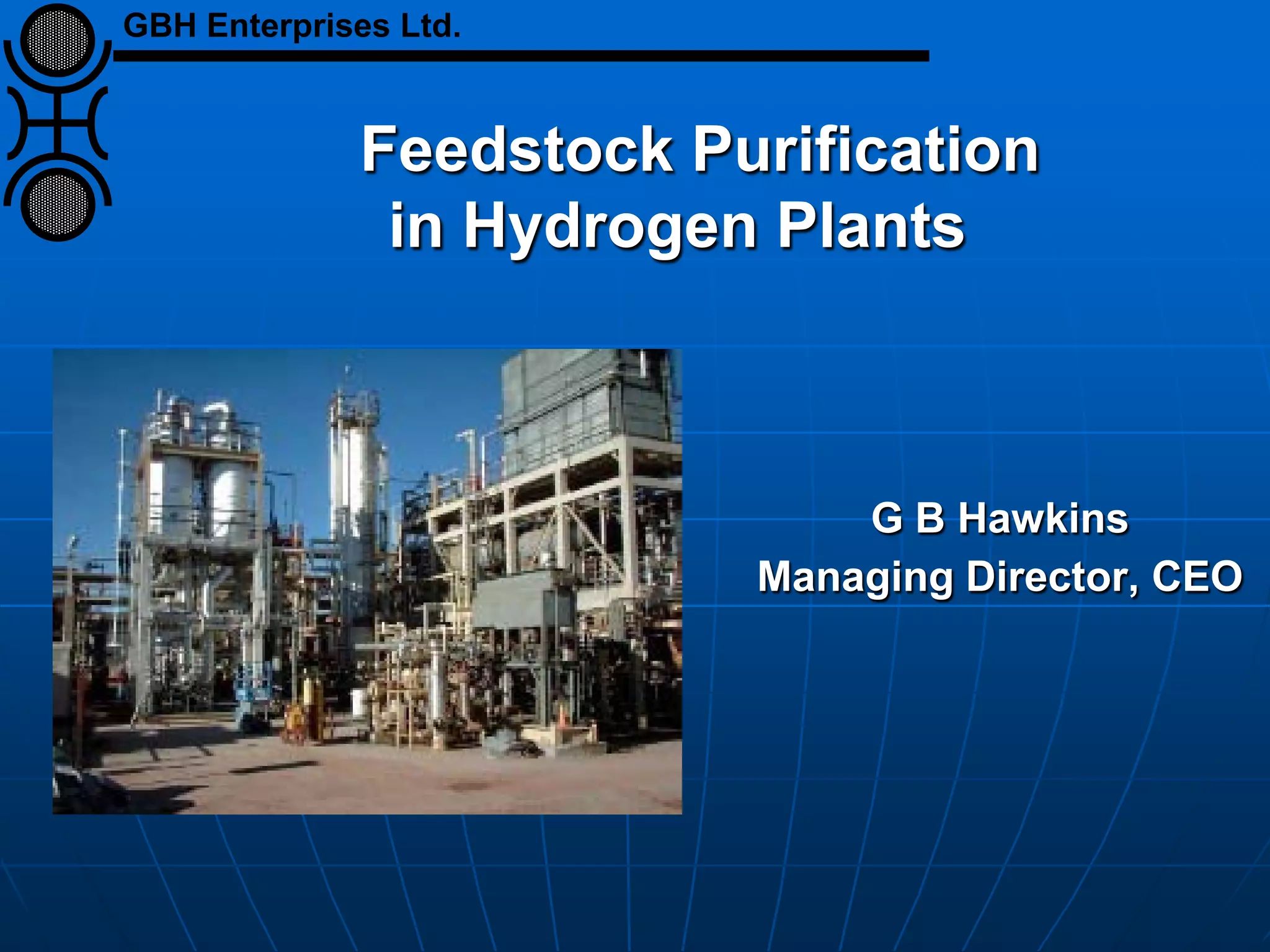
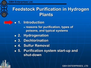


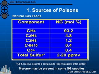
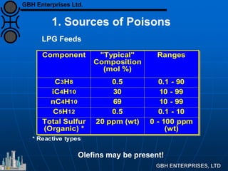

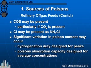
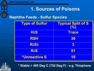
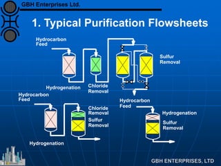
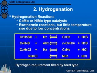
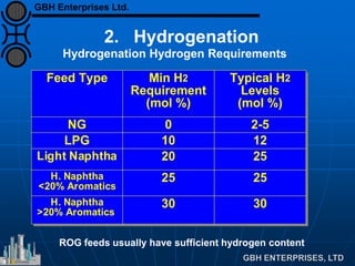
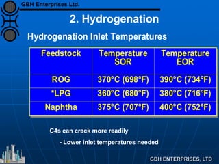
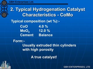
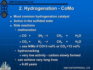

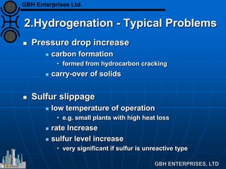
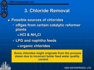
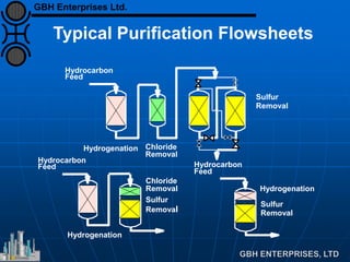


The document discusses the importance of feedstock purification in hydrogen plants, focusing on catalyst requirements and various poisoning agents such as sulfur, chlorides, and heavy metals. It outlines methods for hydrogenation, dechlorination, and sulfur removal, along with typical purification flowsheets and operational conditions. The text emphasizes the need for careful monitoring of feed compositions and purification system performance to maintain plant efficiency and prolong catalyst life.


