Downloaded 129 times
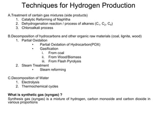
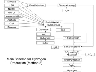
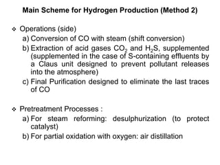
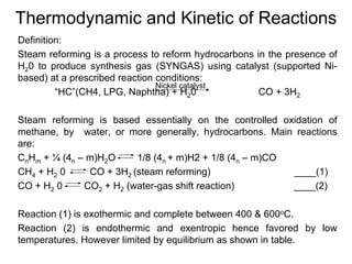
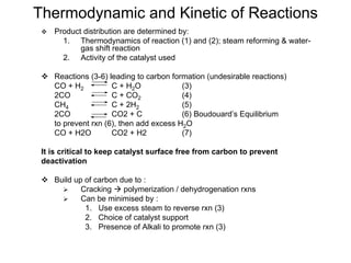
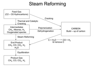
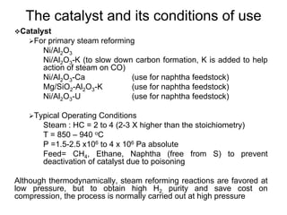
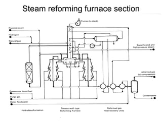
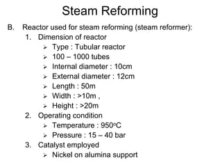
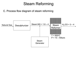
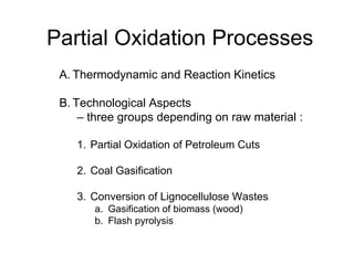
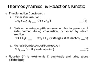
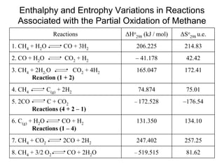
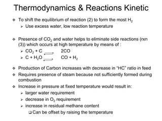
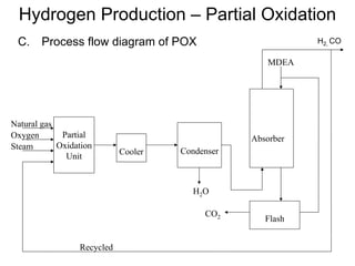
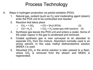
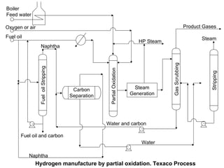
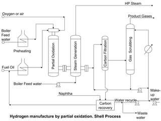
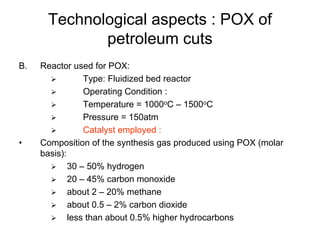
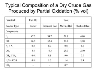
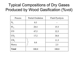
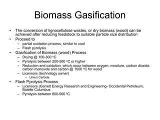

This document discusses various techniques for hydrogen production including treatment of gas mixtures, decomposition of hydrocarbons, and decomposition of water. It provides details on steam reforming, partial oxidation processes, and electrolysis of water. Steam reforming involves a catalytic reaction of methane and steam at high temperatures and pressures to produce hydrogen and carbon monoxide. Partial oxidation processes use oxygen and steam in an exothermic reaction to partially oxidize hydrocarbons into hydrogen, carbon monoxide, and carbon dioxide. Electrolysis and thermochemical cycles can also be used to decompose water into hydrogen and oxygen through electrical or thermal means.


![5G Explained! A High Level Overview [Introduction]](https://cdn.slidesharecdn.com/ss_thumbnails/5gexplainedahighleveloverview-260119165306-cc137a3e-thumbnail.jpg?width=640&height=640&fit=bounds)


