Downloaded 1,021 times


![64
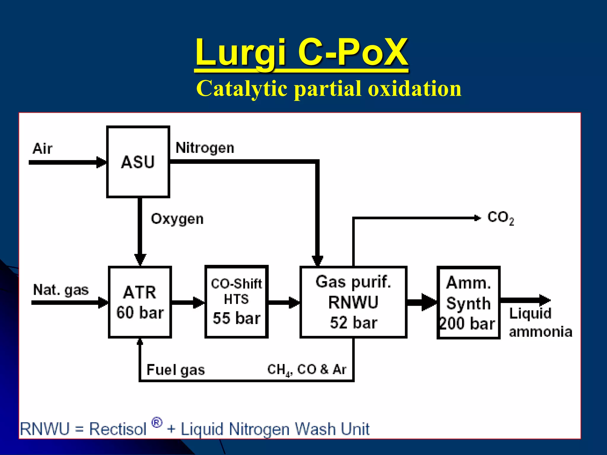
ATR Gas-MPG
pressure [bar] 35 70
temperature inlet [°C] 750 500
temperature outlet [°C] 950 1400
O2 / natural gas [mol/mol] 0.4 0.7
steam / natural gas [mol/mol] 1.5 … 1.7 0.05…0.2
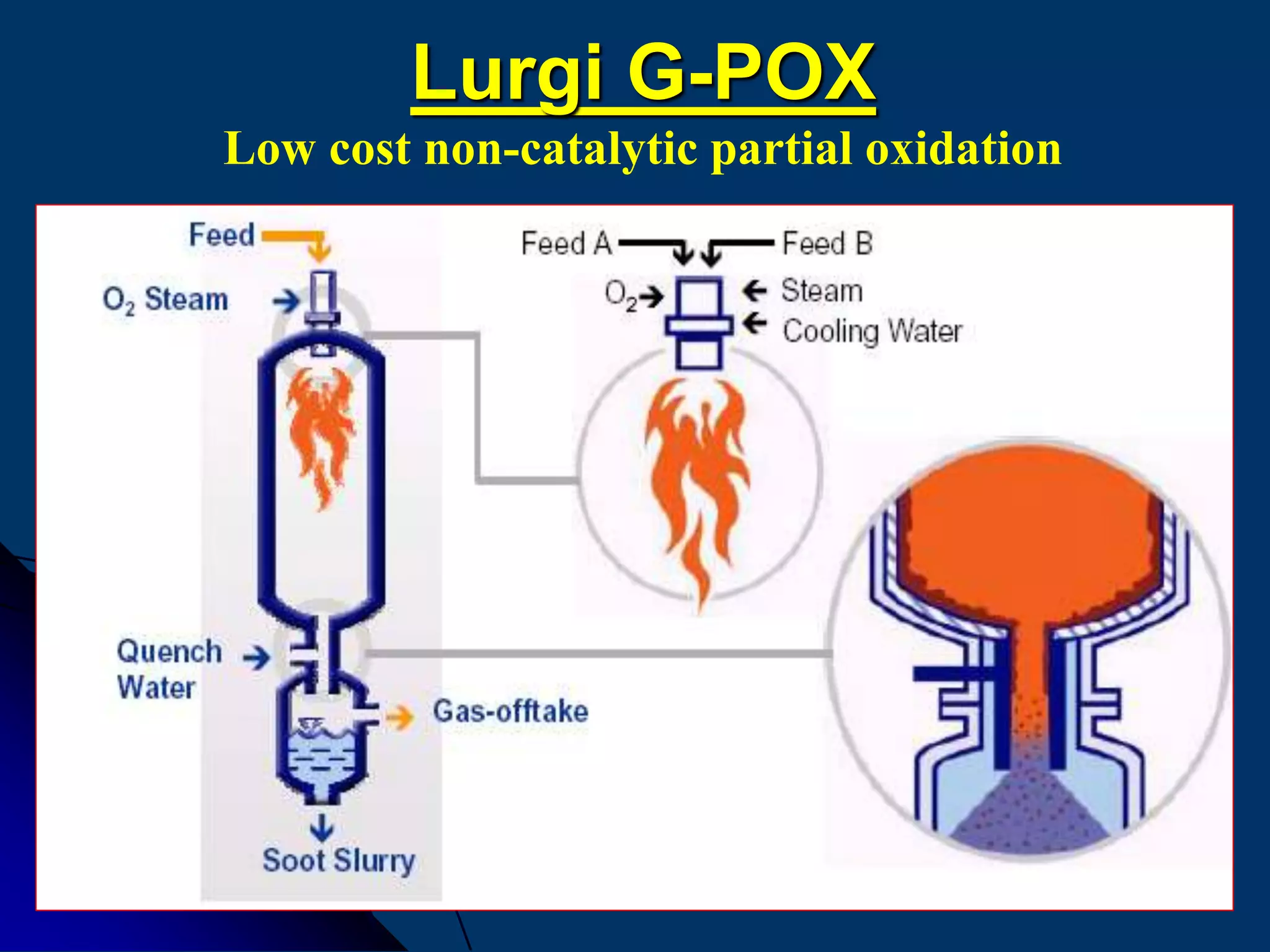
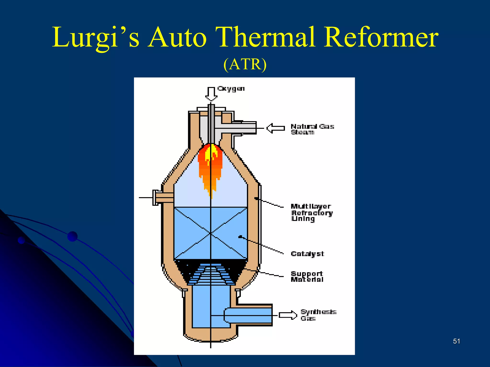
Comparison of Lurgi´s catalytic and non-catalytic partial
oxidation processes](https://image.slidesharecdn.com/variousammoniatechnologyrepaired-150323012840-conversion-gate01/75/Various-ammonia-technology-64-2048.jpg)

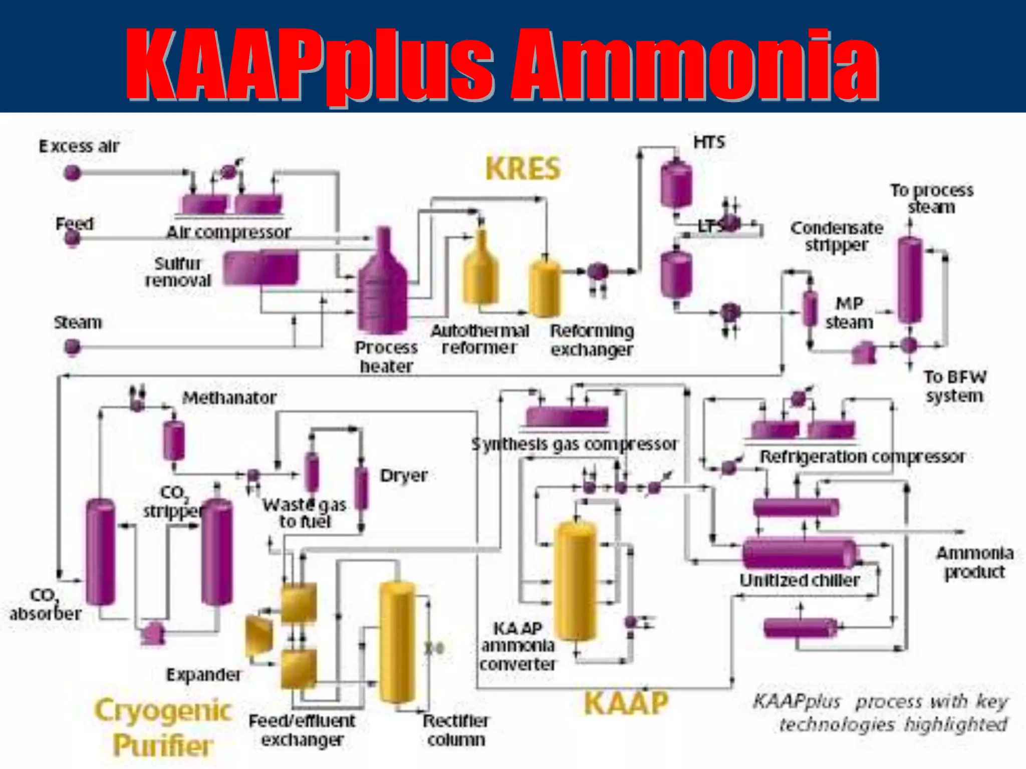


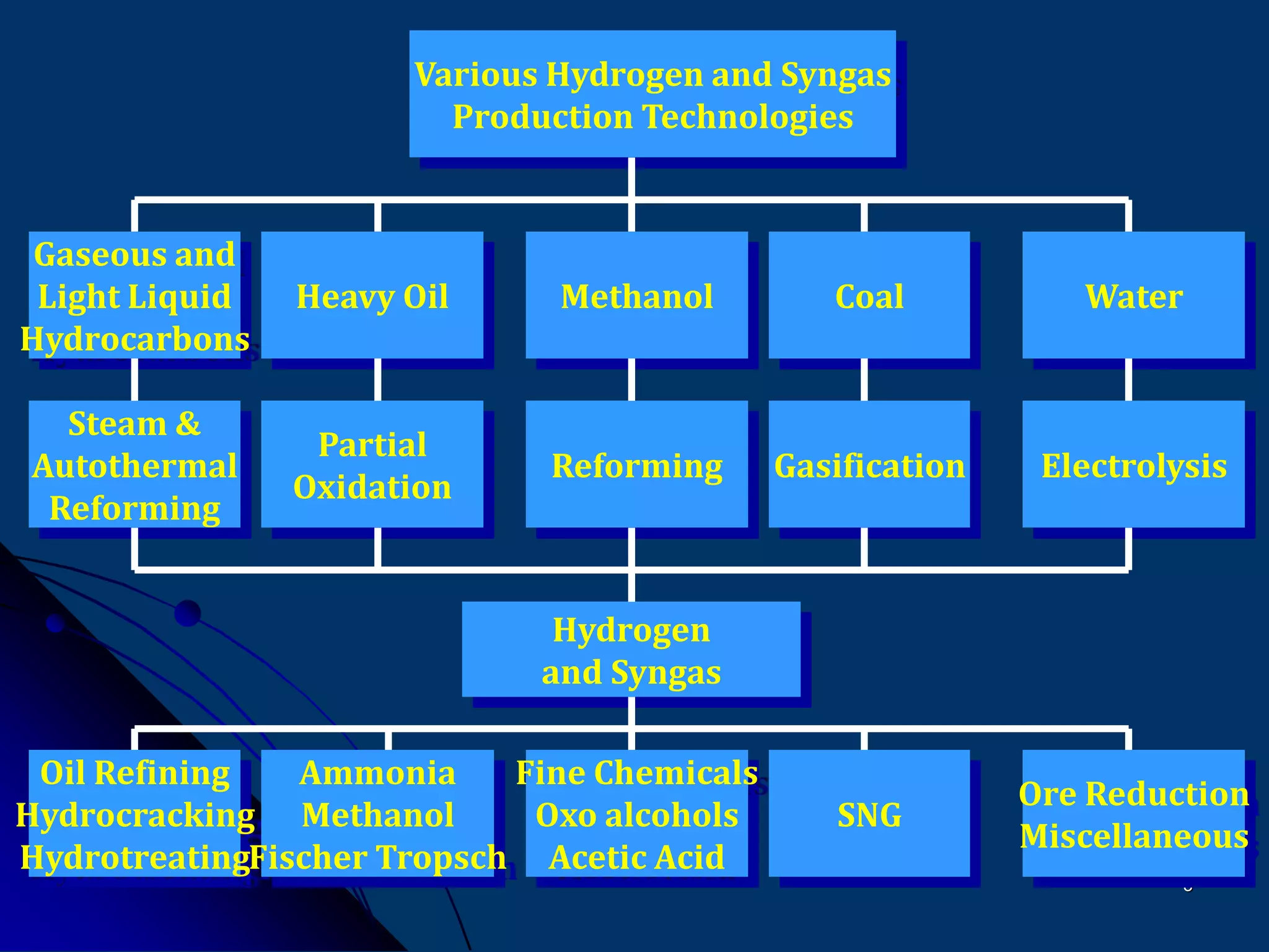
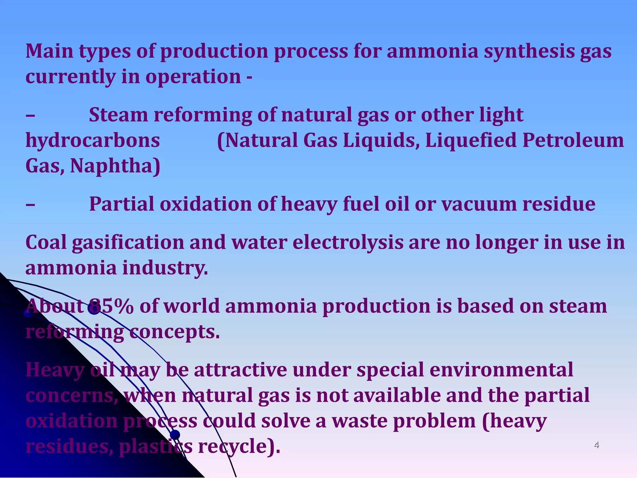
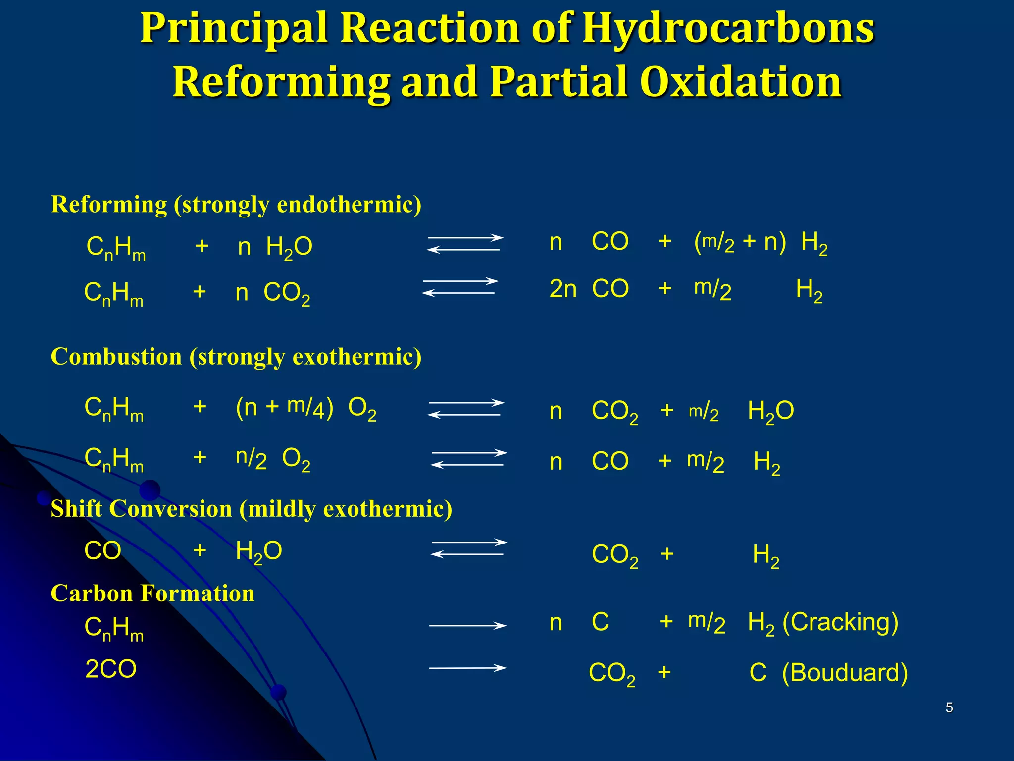
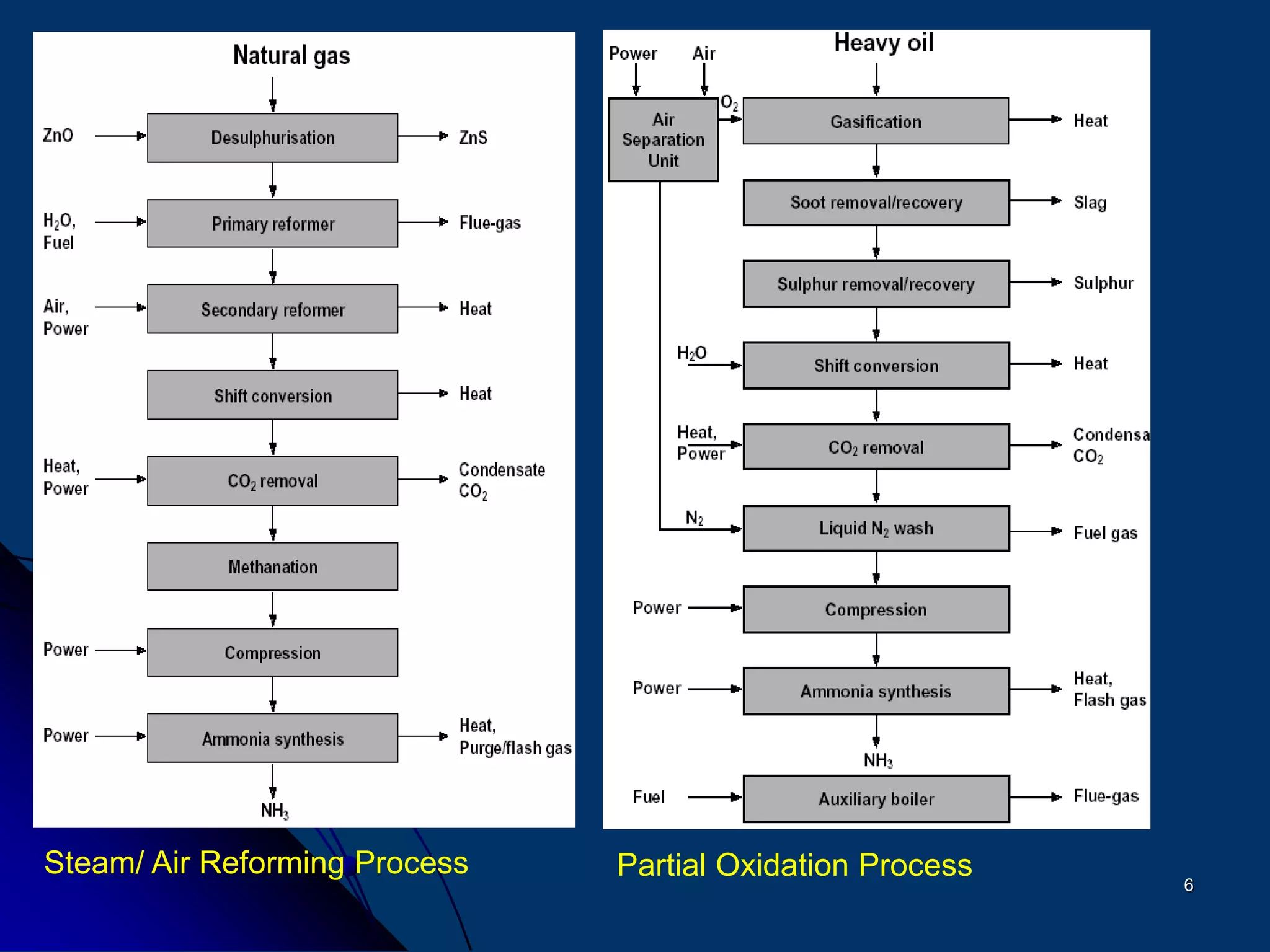
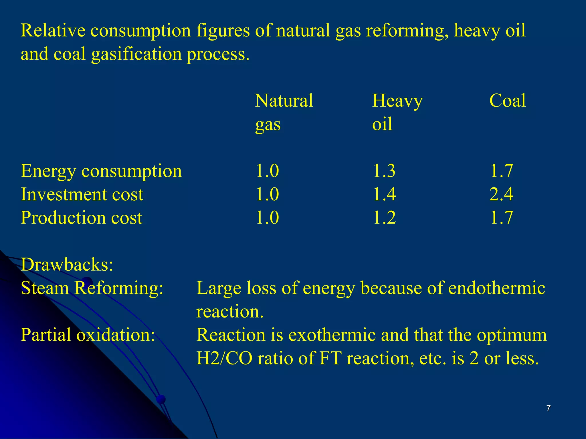
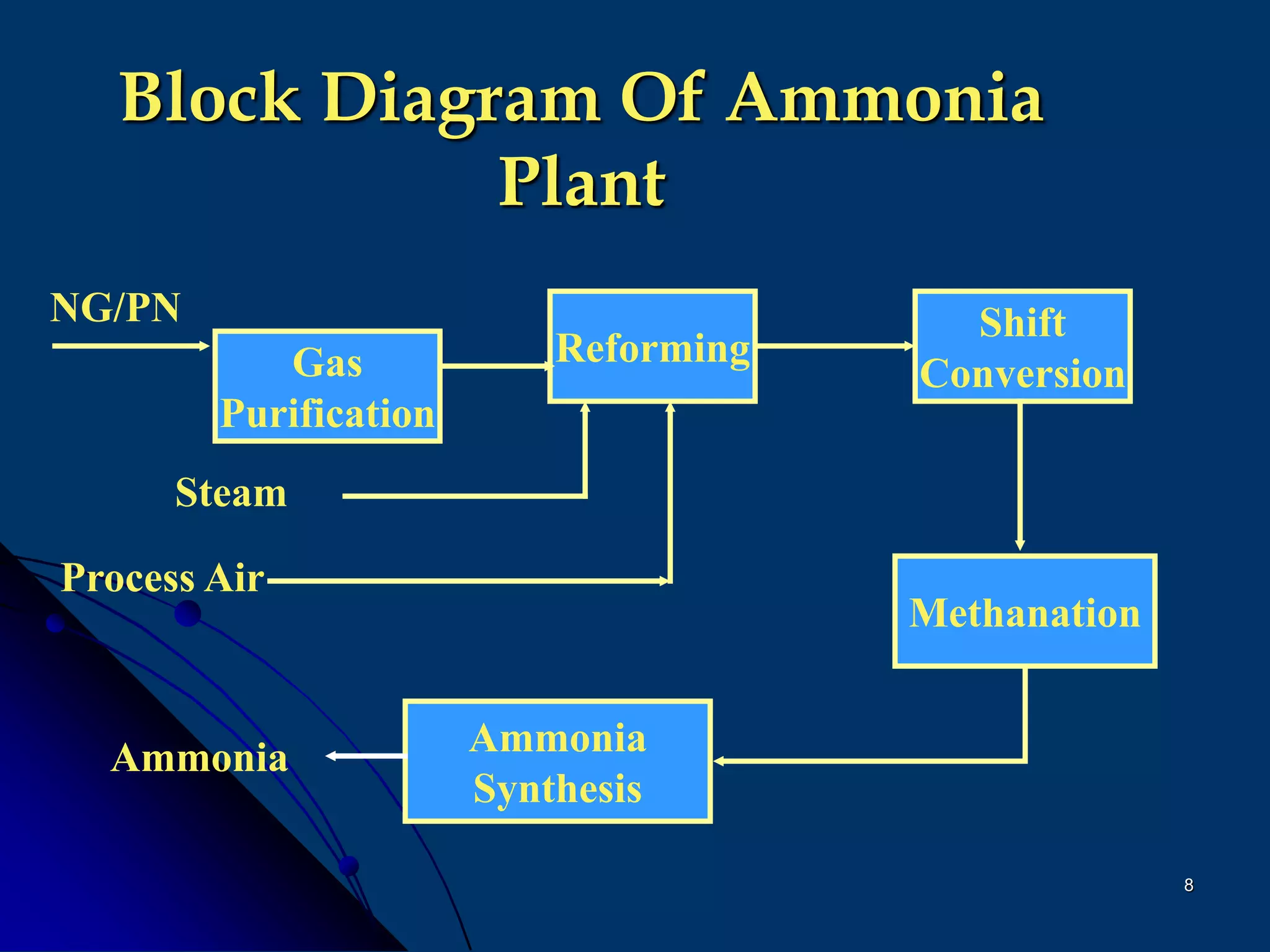
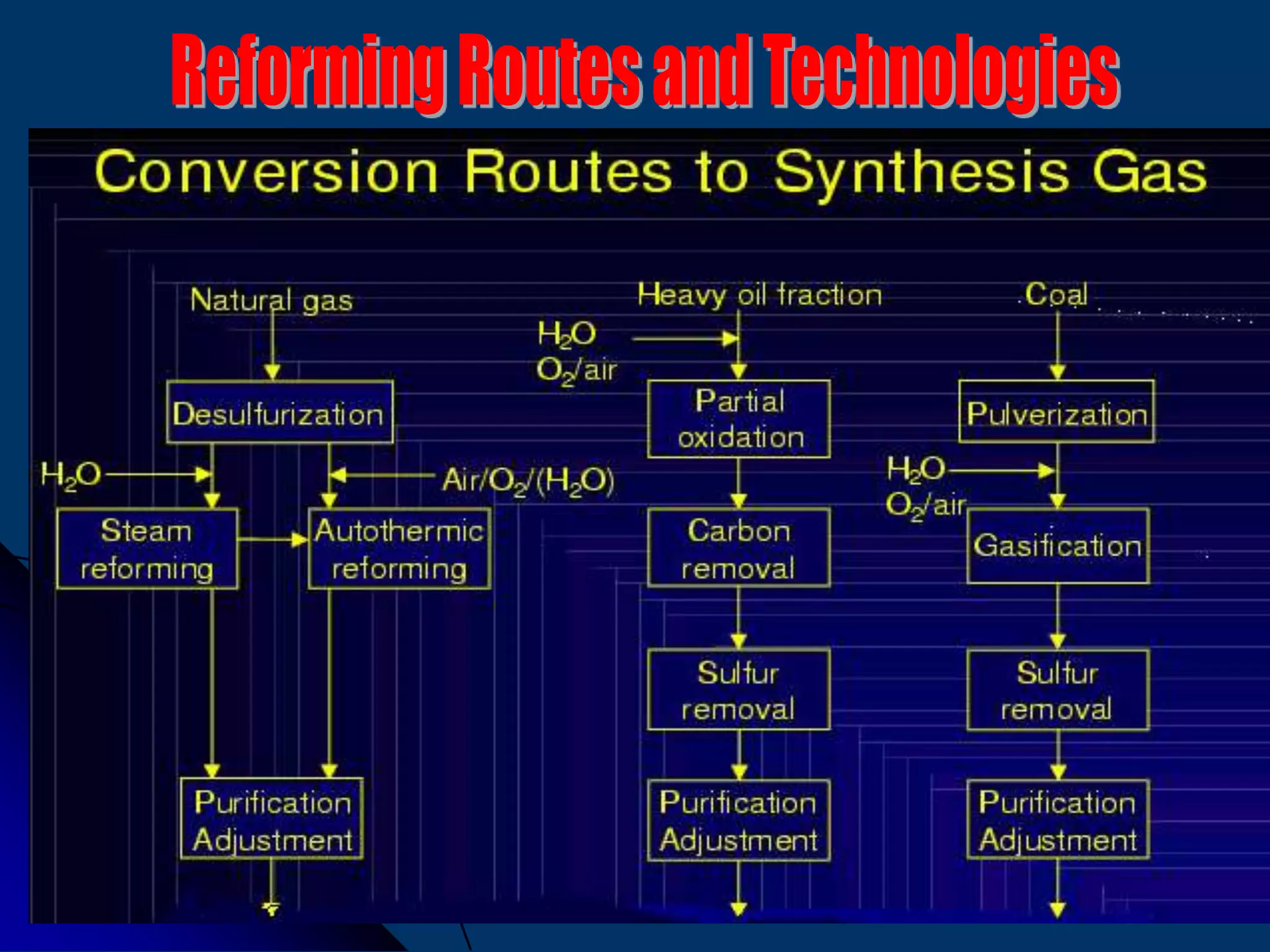
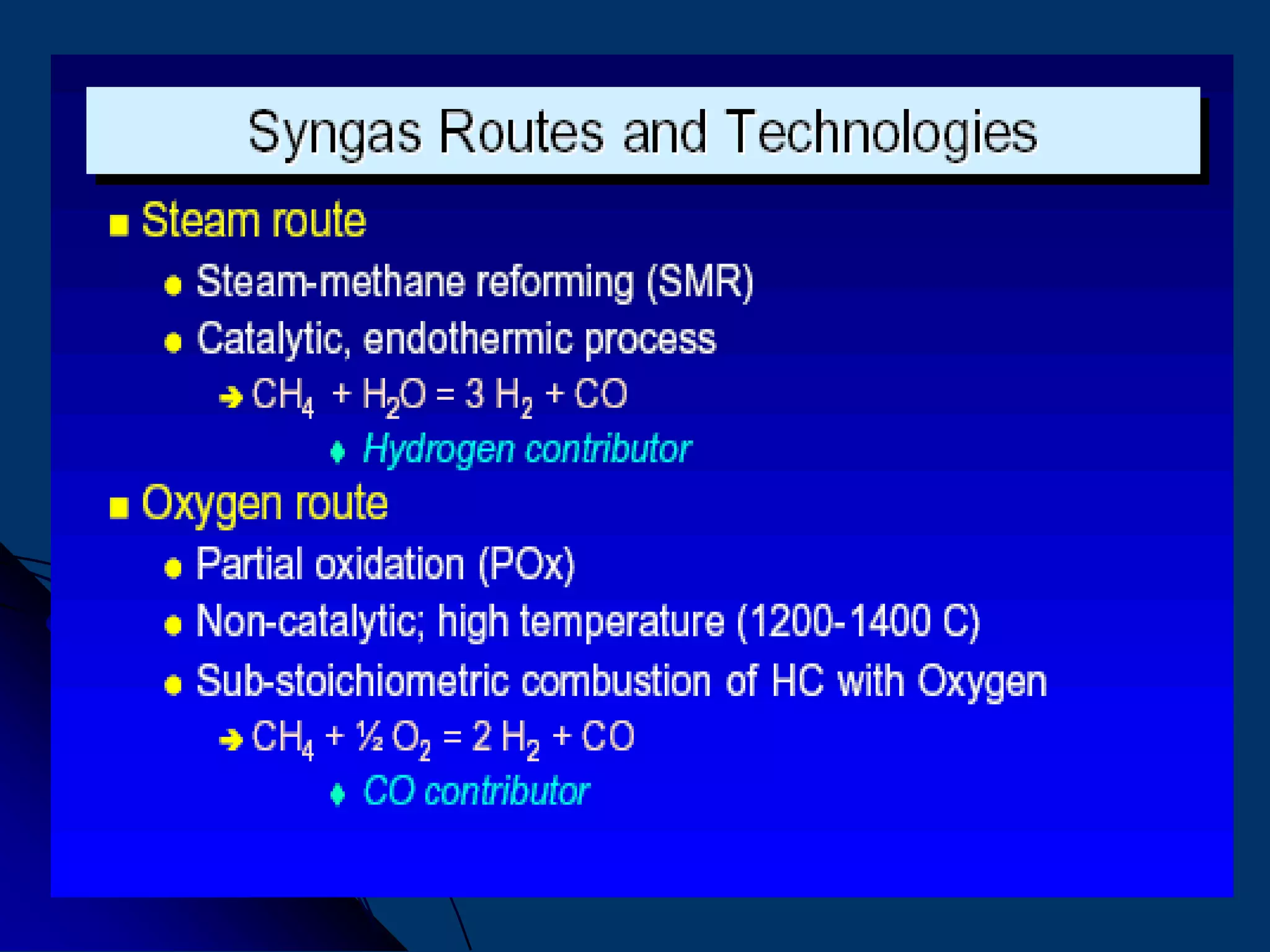
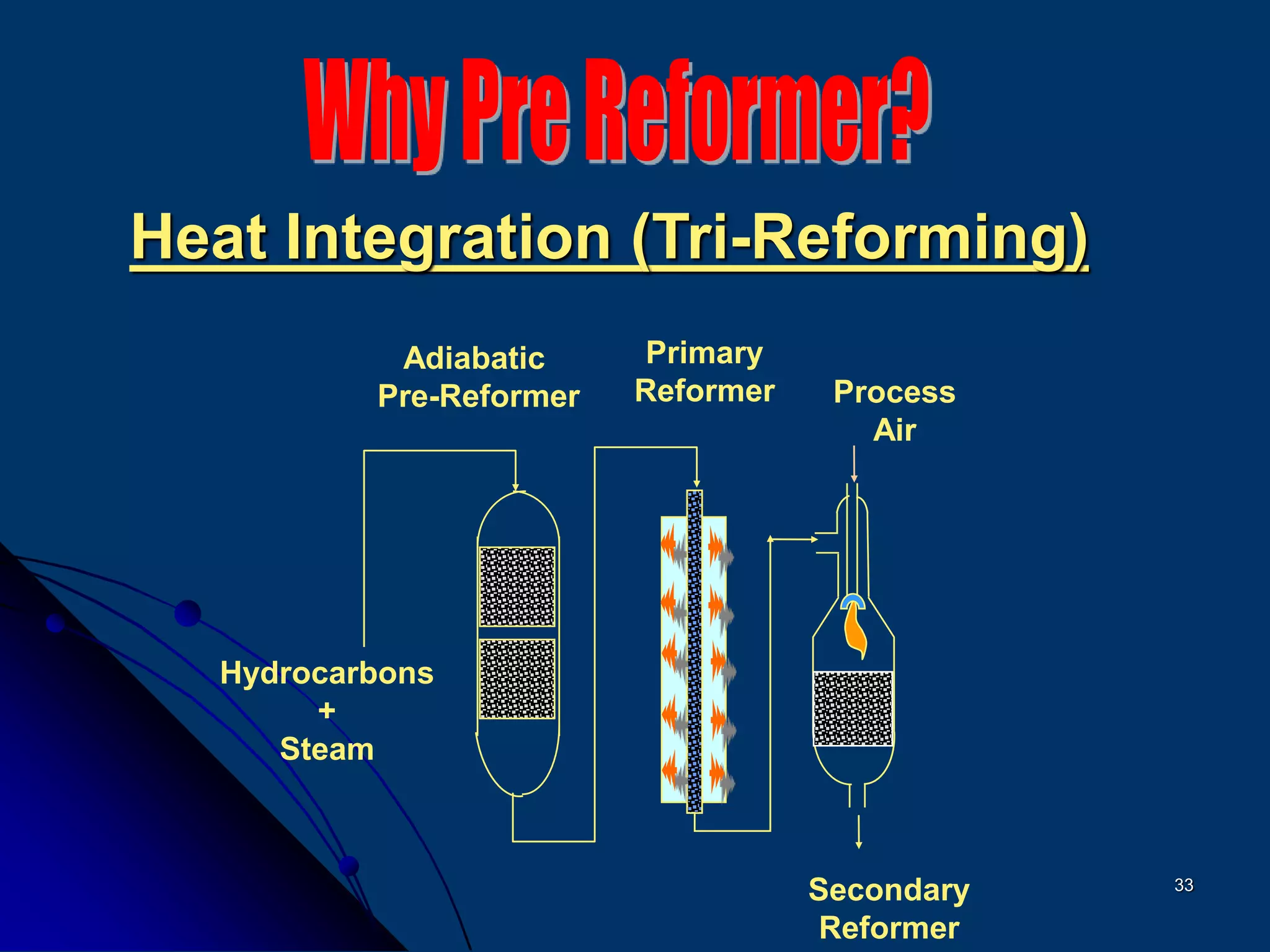
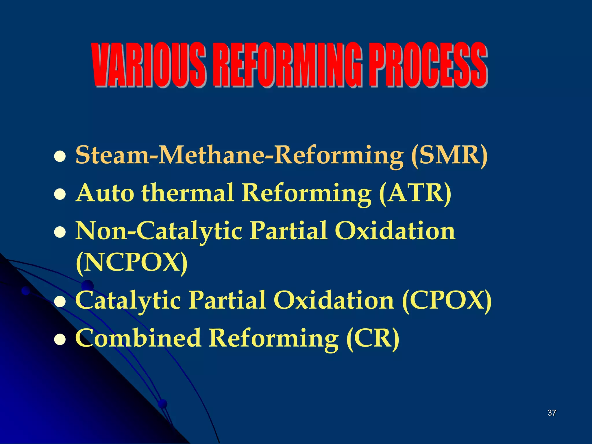
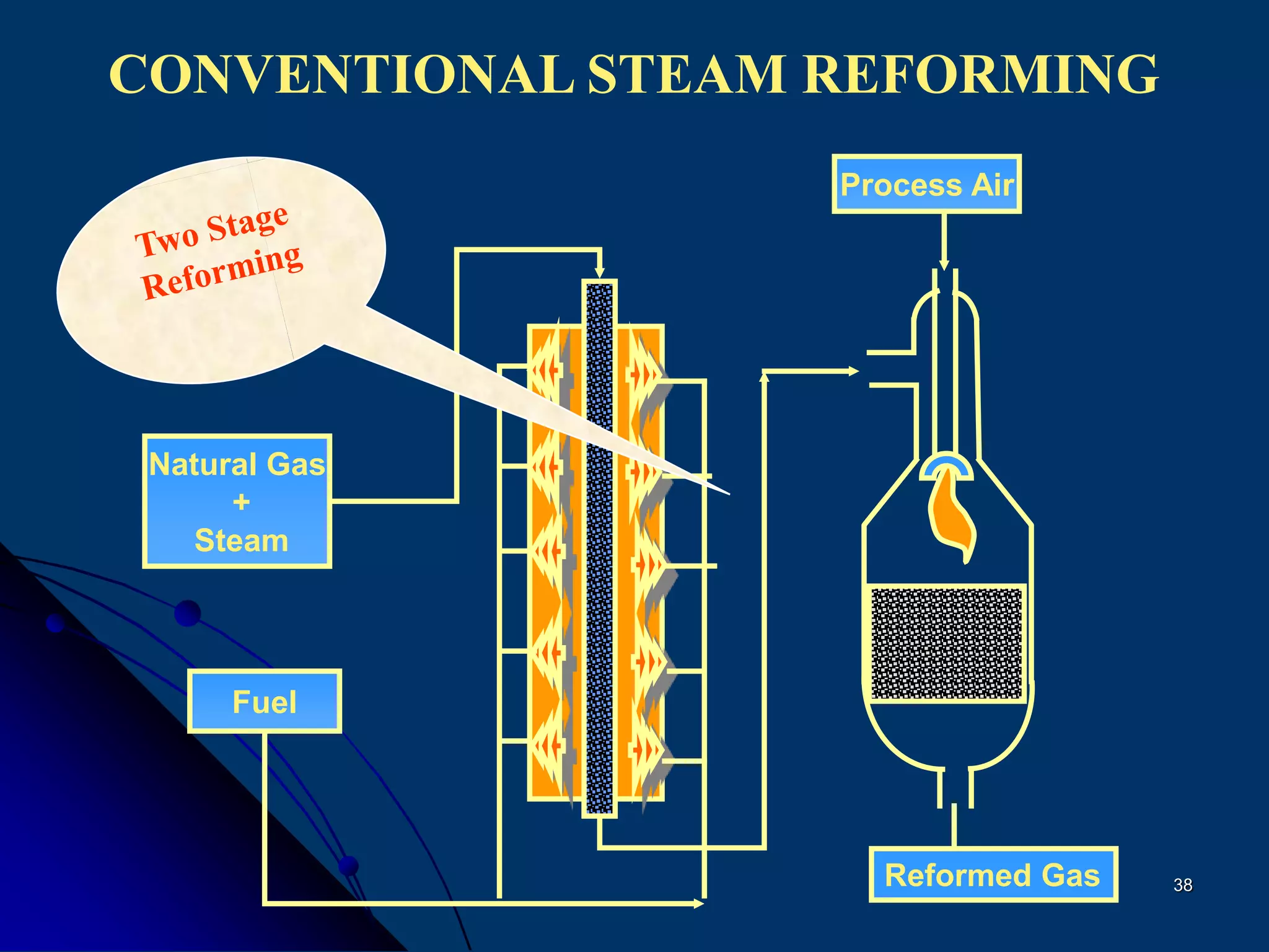
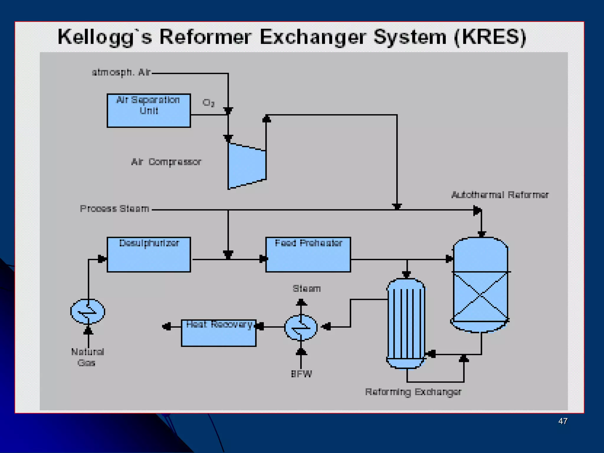
The document discusses various technologies for producing hydrogen and synthesis gas, including steam reforming, partial oxidation, coal gasification, and water electrolysis. It provides an overview of the main industrial processes used for ammonia synthesis gas production, noting that about 85% is based on steam reforming of natural gas or other light hydrocarbons. Various hydrogen and syngas production processes are also compared in terms of energy consumption, investment cost, and production cost.


![Kbr[1] report](https://cdn.slidesharecdn.com/ss_thumbnails/kbr1-160104072613-thumbnail.jpg?width=640&height=640&fit=bounds)


