Downloaded 537 times
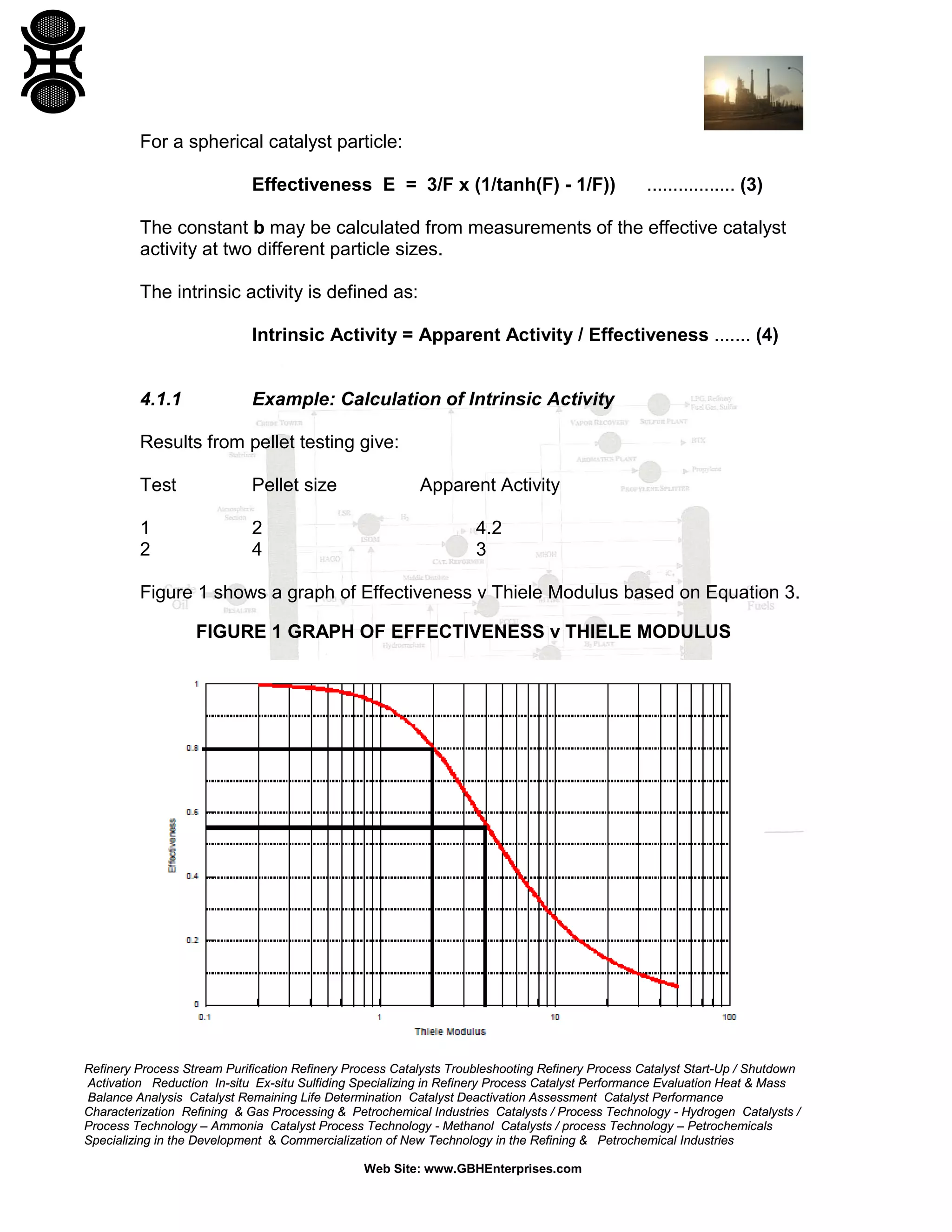
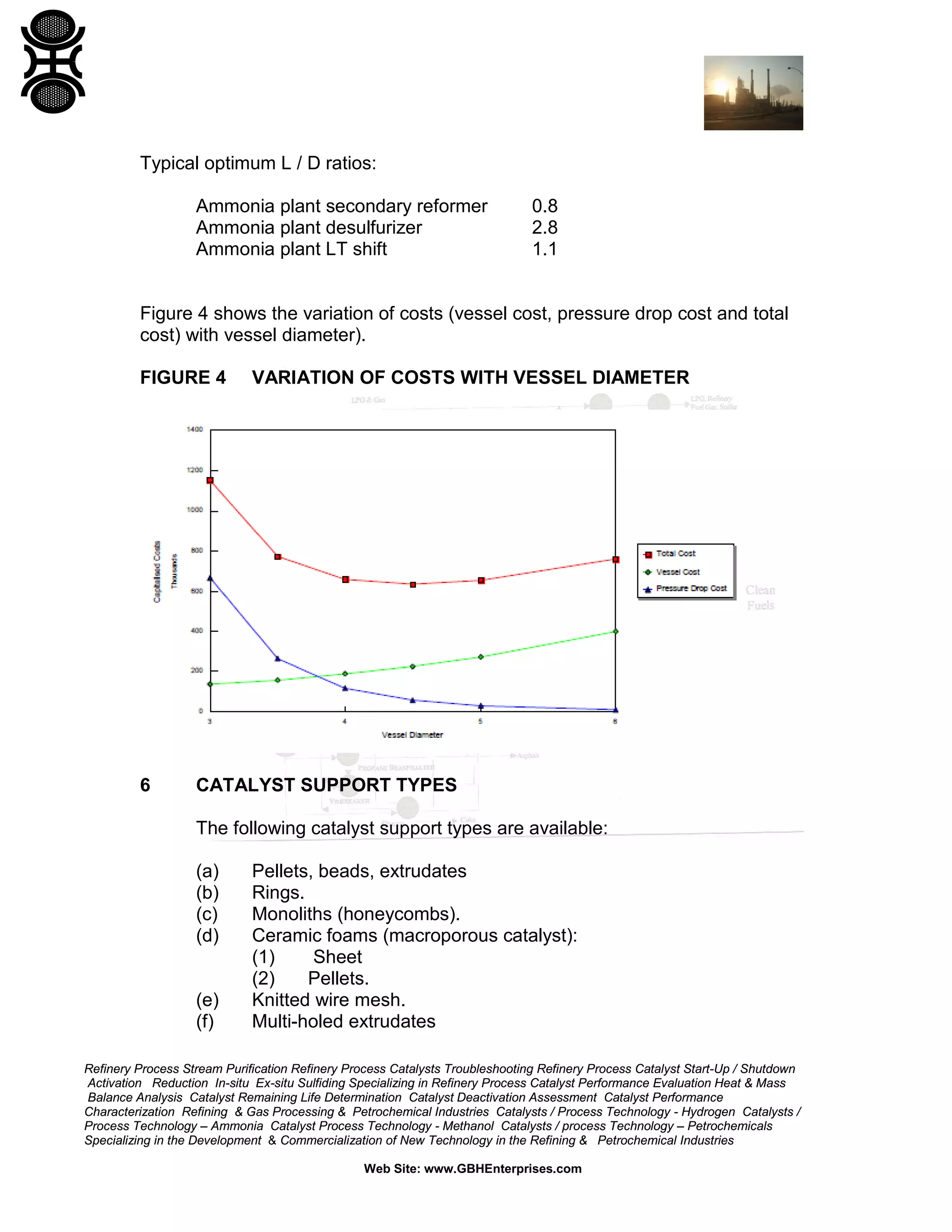


The document is a comprehensive process engineering guide by GBH Enterprises, focusing on reactor and catalyst design specifically for refining and petrochemical industries. It addresses key parameters such as catalyst size, shape, voidage, and density and provides essential equations for optimizing catalyst performance and reactor geometry. Additionally, it outlines various catalyst support types and design considerations, emphasizing the need for process engineers to evaluate these factors for efficient operations.


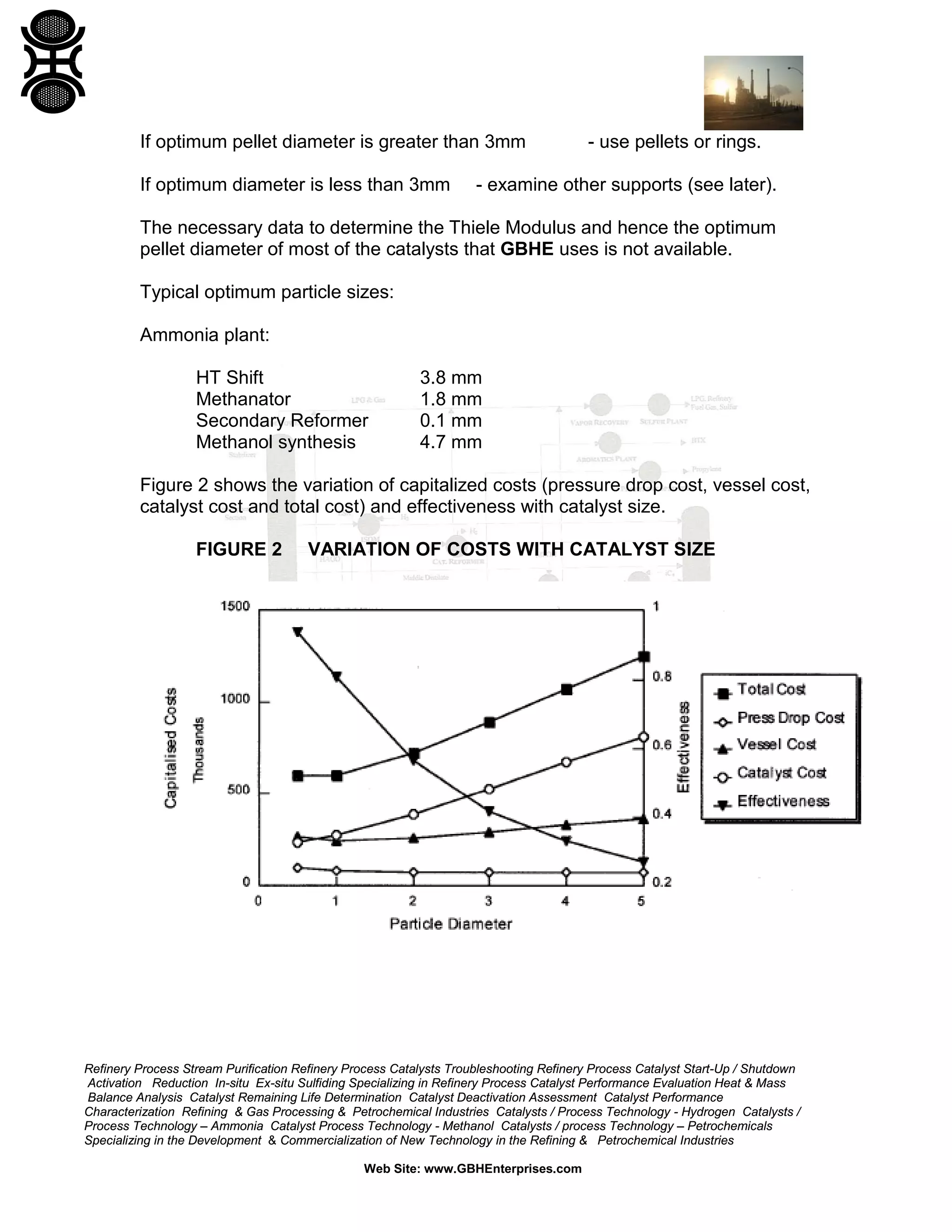
![Coded Agents – with UiPath SDK + LangGraph [Virtual Hands-on Workshop]](https://cdn.slidesharecdn.com/ss_thumbnails/codedagentsdeck-251215155422-5497c599-thumbnail.jpg?width=640&height=640&fit=bounds)


