Downloaded 170 times
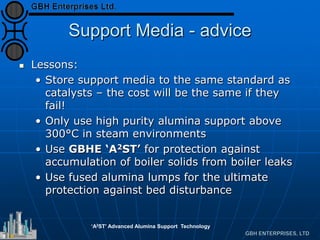
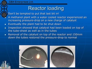


This document presents an analysis of catalyst mal-operation incidents in syngas production, providing recommendations for plant operators to avoid costly outages and catalyst losses. It covers topics such as catalyst loading, burner operation during start-up, carbon formation from hydrocarbons, and failures due to condensation. Key lessons emphasize the importance of proper training, catalyst selection, and equipment maintenance to improve operational reliability.


![Getting Started with Apache Spark: Big Data Made Simple [Free Meetup]](https://cdn.slidesharecdn.com/ss_thumbnails/apachesparkgettingstarted-260203175547-8361bcc3-thumbnail.jpg?width=640&height=640&fit=bounds)


