Downloaded 136 times


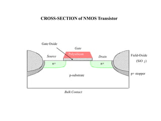


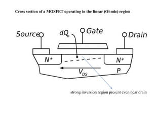


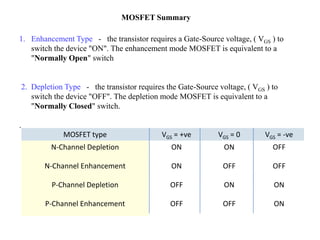


The document describes the structure and operation of a metal-oxide-semiconductor field-effect transistor (MOSFET). It details the three main components: the gate, source, and drain electrodes separated by a thin gate oxide layer. Depending on the gate voltage relative to the threshold voltage, the MOSFET can be in one of three operating modes - cutoff, linear, or saturation - determining whether current flows between the source and drain. Enhancement mode MOSFETs require a gate voltage to turn on, functioning like a normally open switch, while depletion mode MOSFETs require a gate voltage to turn off, functioning like a normally closed switch.


