Downloaded 137 times

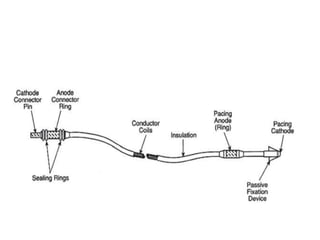
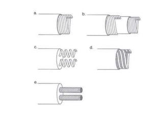
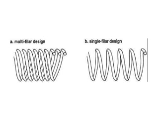
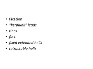
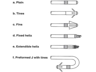
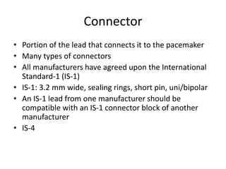
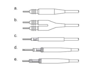
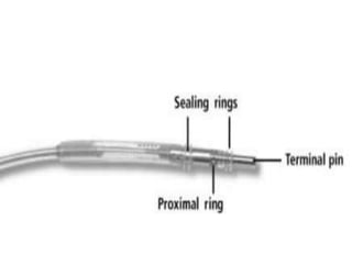


Pacemakers have several key components including a battery, circuitry, connector block, and leads. Battery technology has evolved from mercury zinc to lithium iodium batteries with longer lifespans. Pacemaker circuitry is now highly integrated with microprocessors and data storage. Leads contain electrodes, insulation, and fixation mechanisms. Pacemakers can be programmed to function in different modes depending on sensing and pacing of the atria and ventricles. Parameters like rate response, refractory periods, and mode switching algorithms allow pacemakers to function adaptively based on patient activity and heart rhythm.


