Downloaded 1,760 times

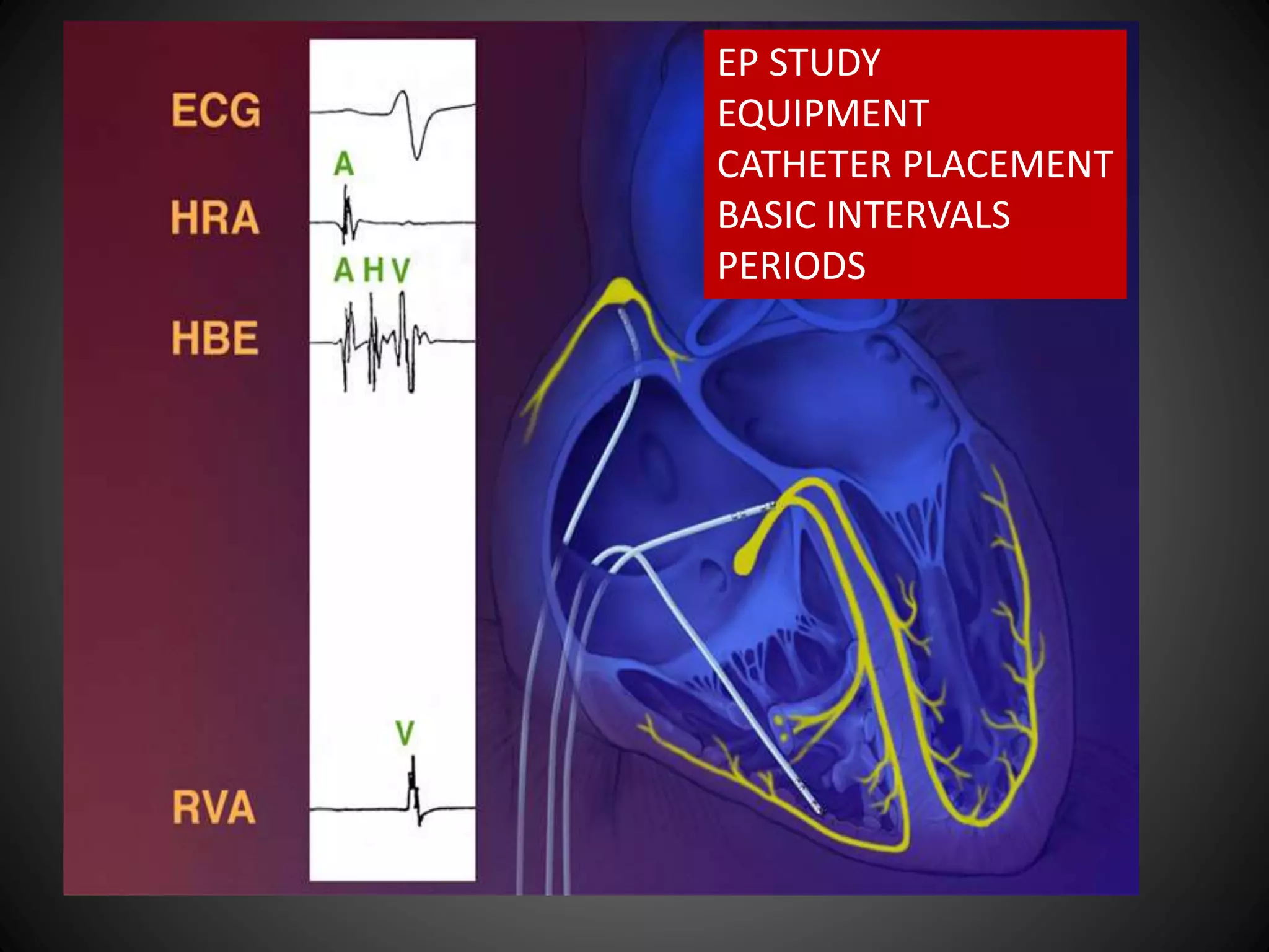
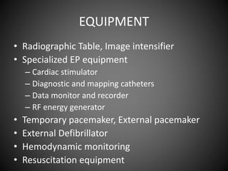
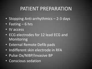

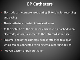
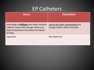
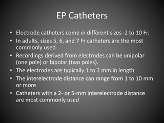
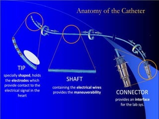
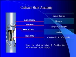
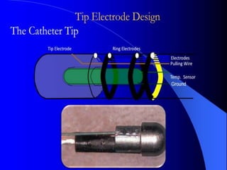
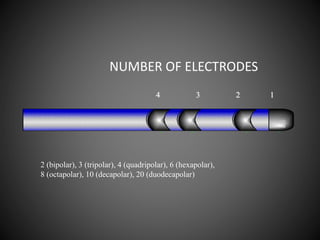
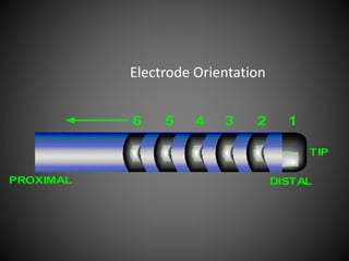
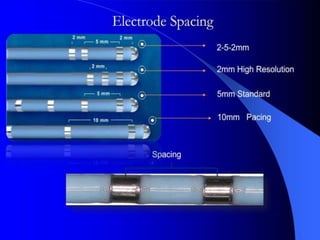
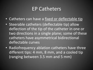
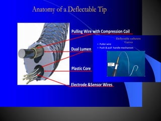

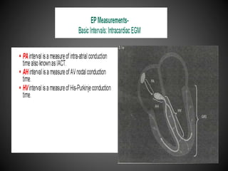
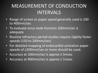
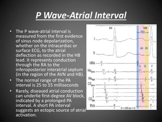
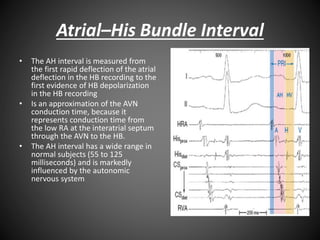
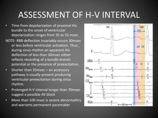
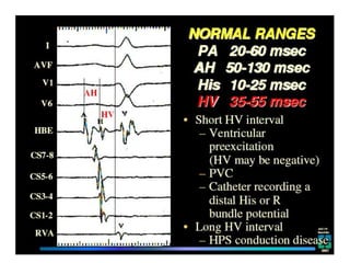
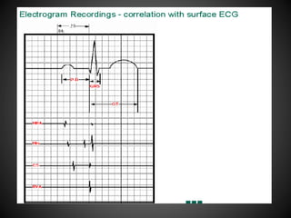
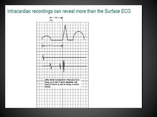
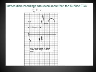
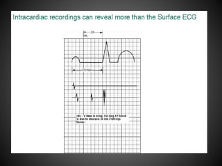
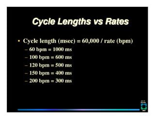
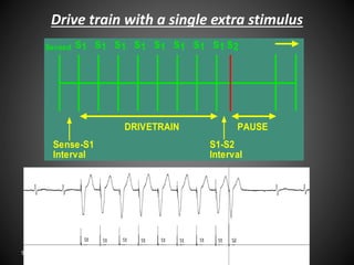
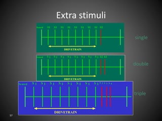
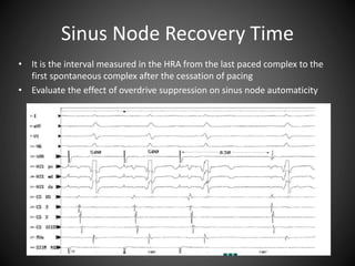


This document describes equipment, catheters, and basic intervals used in electrophysiology (EP) studies. It discusses radiographic tables, EP equipment like cardiac stimulators and mapping/ablation catheters. Patient preparation includes fasting, IV access, monitoring equipment. EP catheters come in different sizes and have electrodes for recording electrical activity. Basic intervals measured include P wave to atrial interval, atrial-His bundle interval, His-ventricular interval, and sinus node recovery time. Drive train stimulation with single, double, or triple extra stimuli is used. The document continues with further discussions of EP protocols, arrhythmias, ablation, and pre-excitation pathways.


![EPS part 2 FINAL [Autosaved].pptx........](https://cdn.slidesharecdn.com/ss_thumbnails/epspart2finalautosaved-250127140443-78c2d1e9-thumbnail.jpg?width=640&height=640&fit=bounds)