Downloaded 290 times
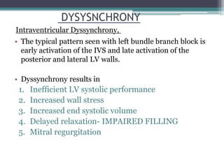
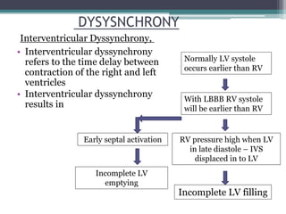
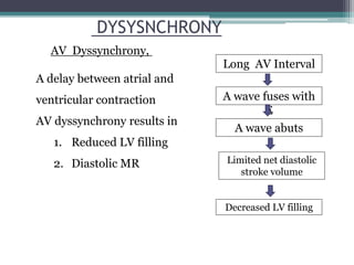
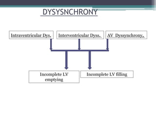

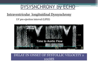
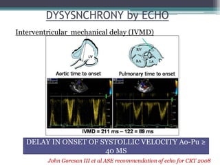
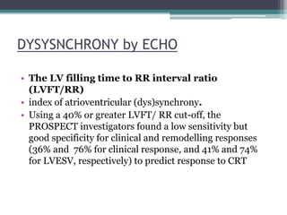
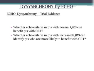
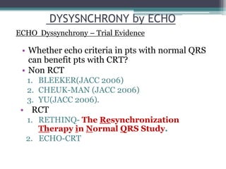
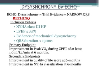
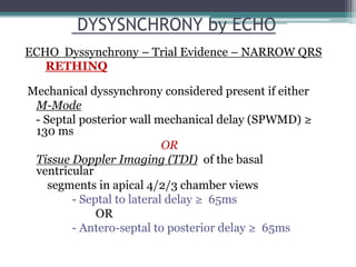
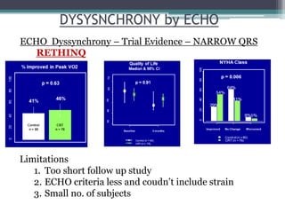
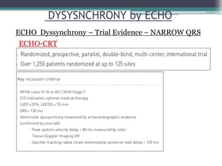
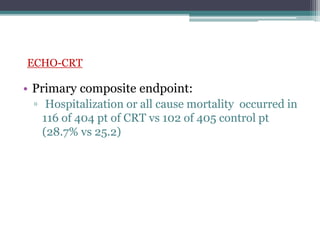
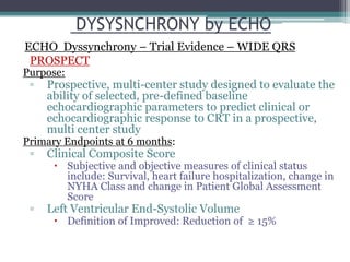
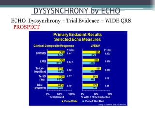
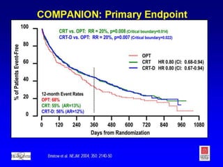
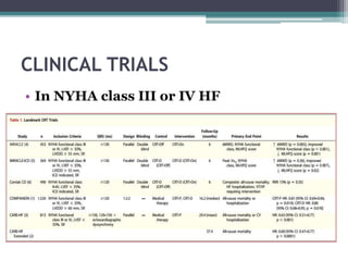
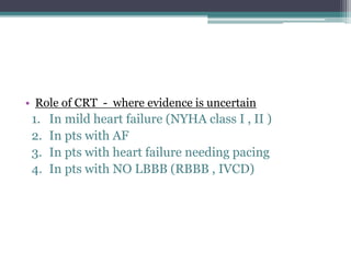
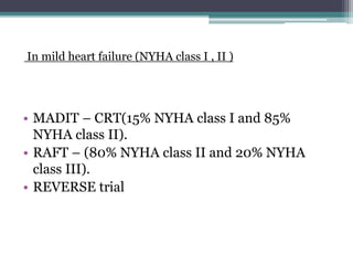
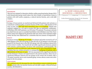
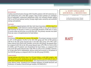
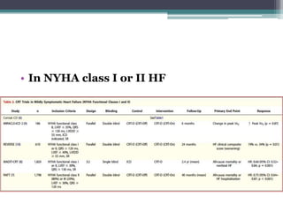
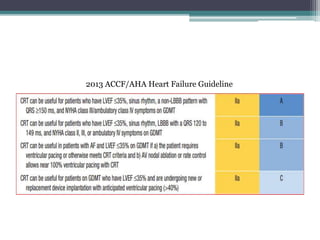


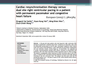
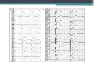
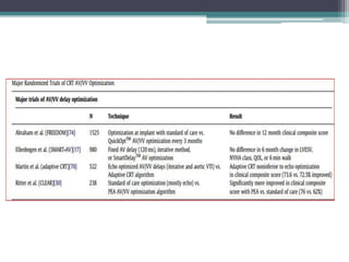
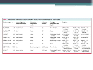
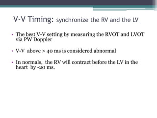
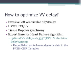


This document provides an overview of cardiac resynchronization therapy (CRT), including indications, assessment of dyssynchrony, rationale/mechanism, trials, procedures, and programming. It discusses the types and assessment of cardiac dyssynchrony using ECG, echocardiography, MRI, and nuclear imaging. Key trials on CRT are summarized, showing benefits for heart failure patients with reduced ejection fraction and wide QRS duration or echocardiographic evidence of dyssynchrony even in narrow QRS.