Downloaded 138 times
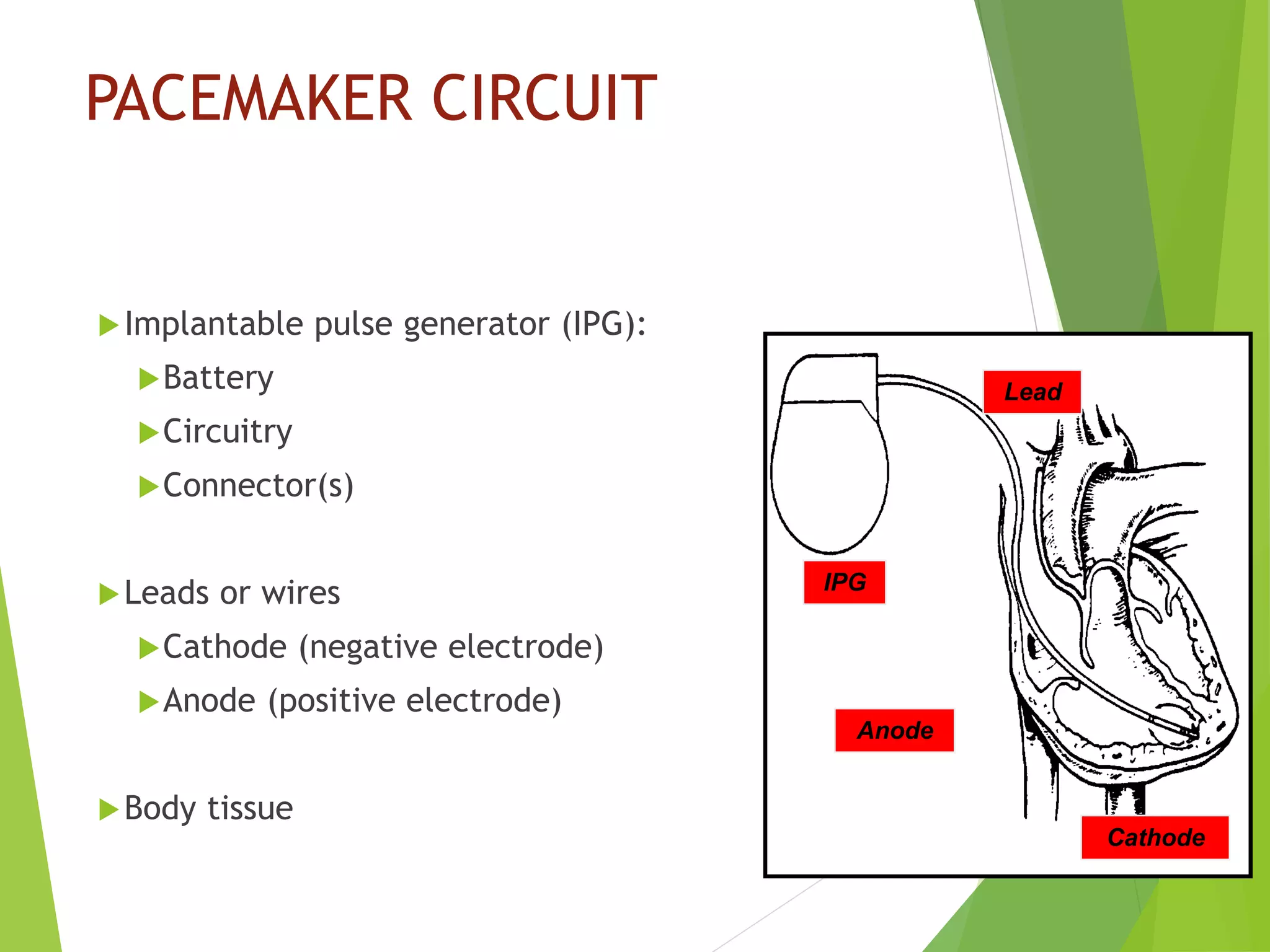
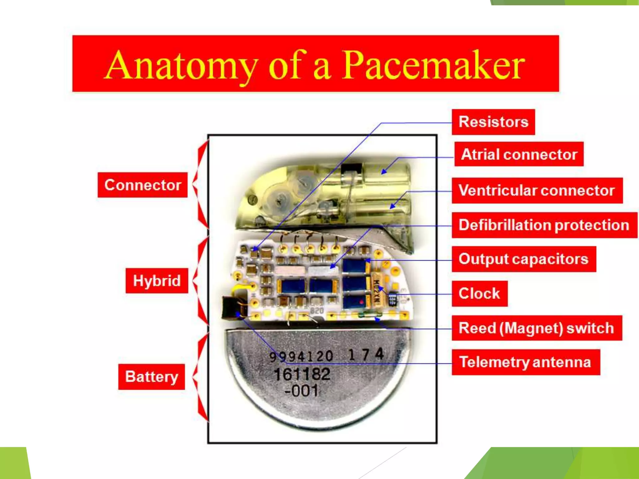
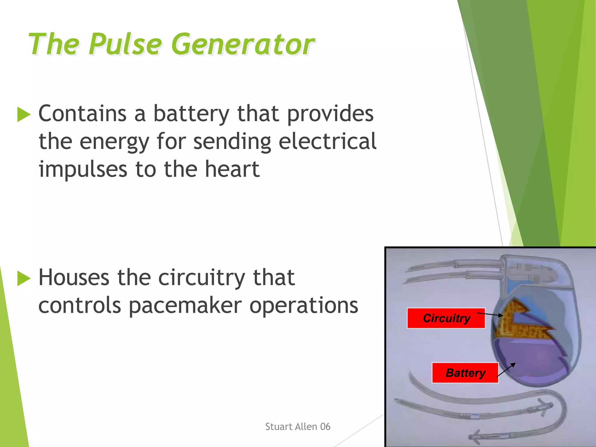
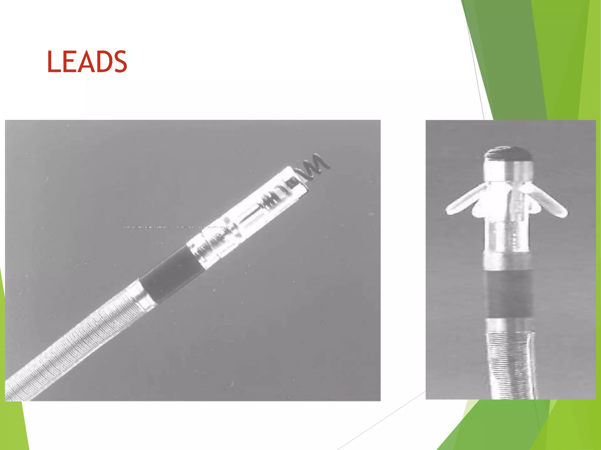
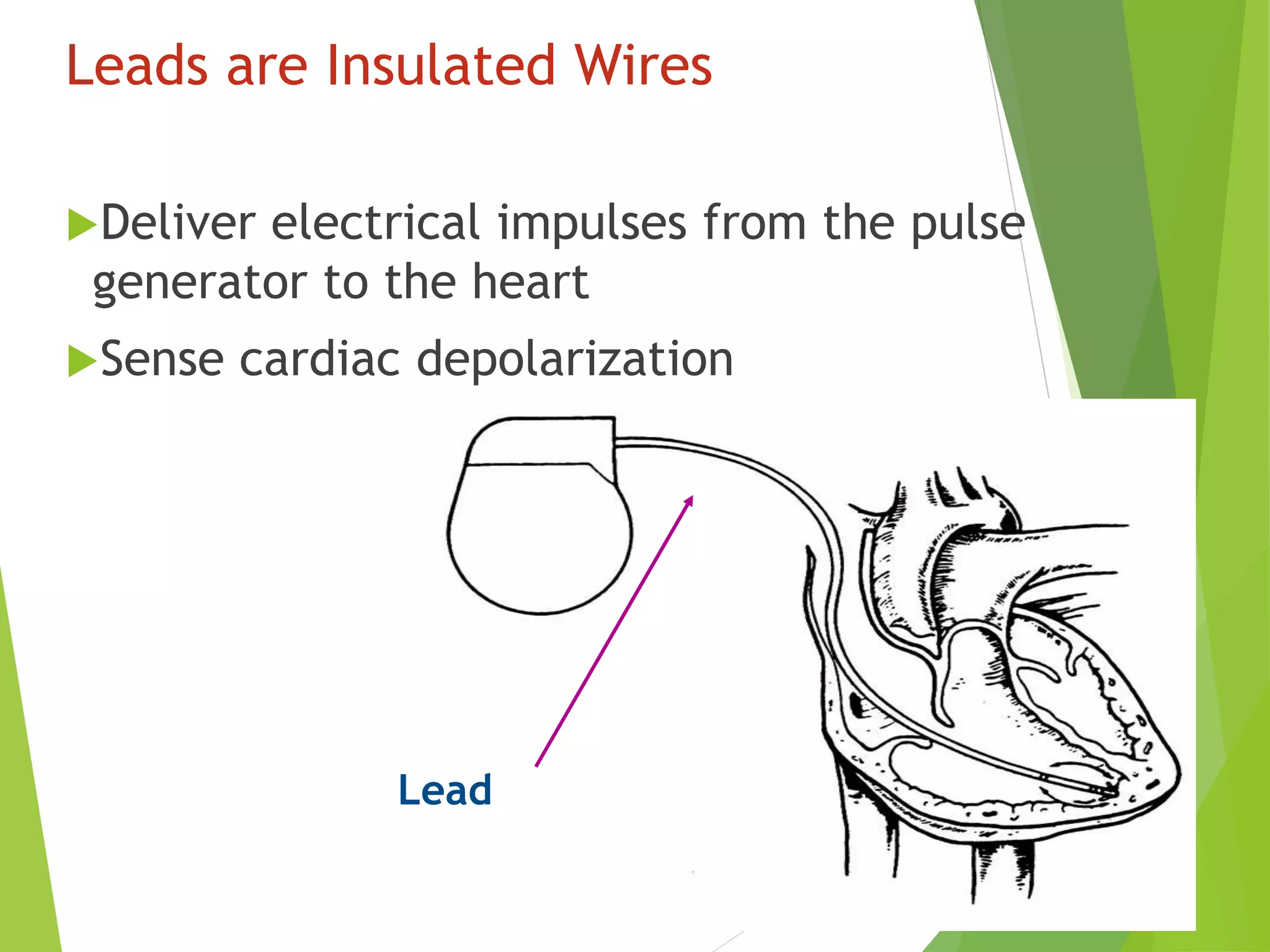
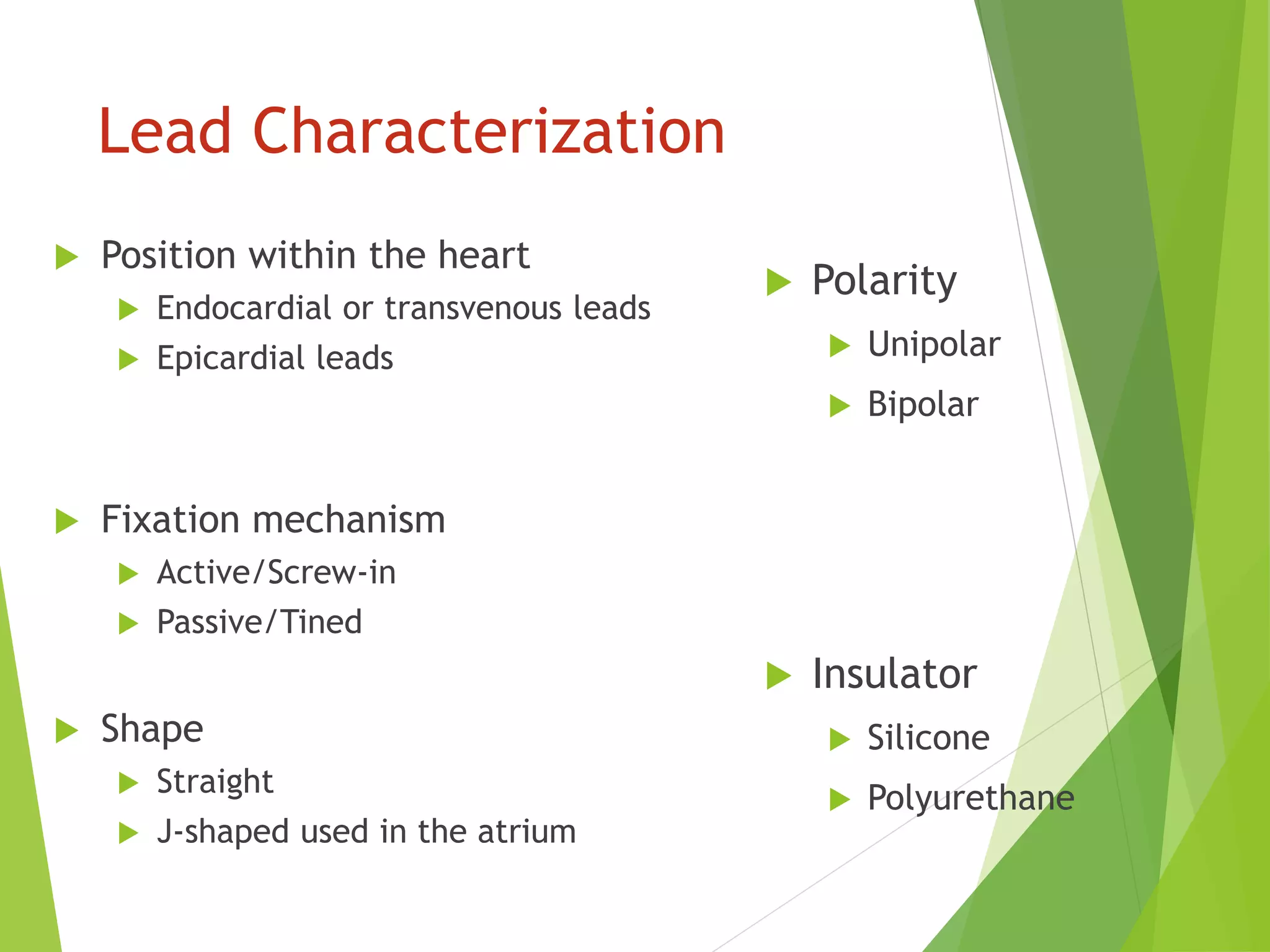
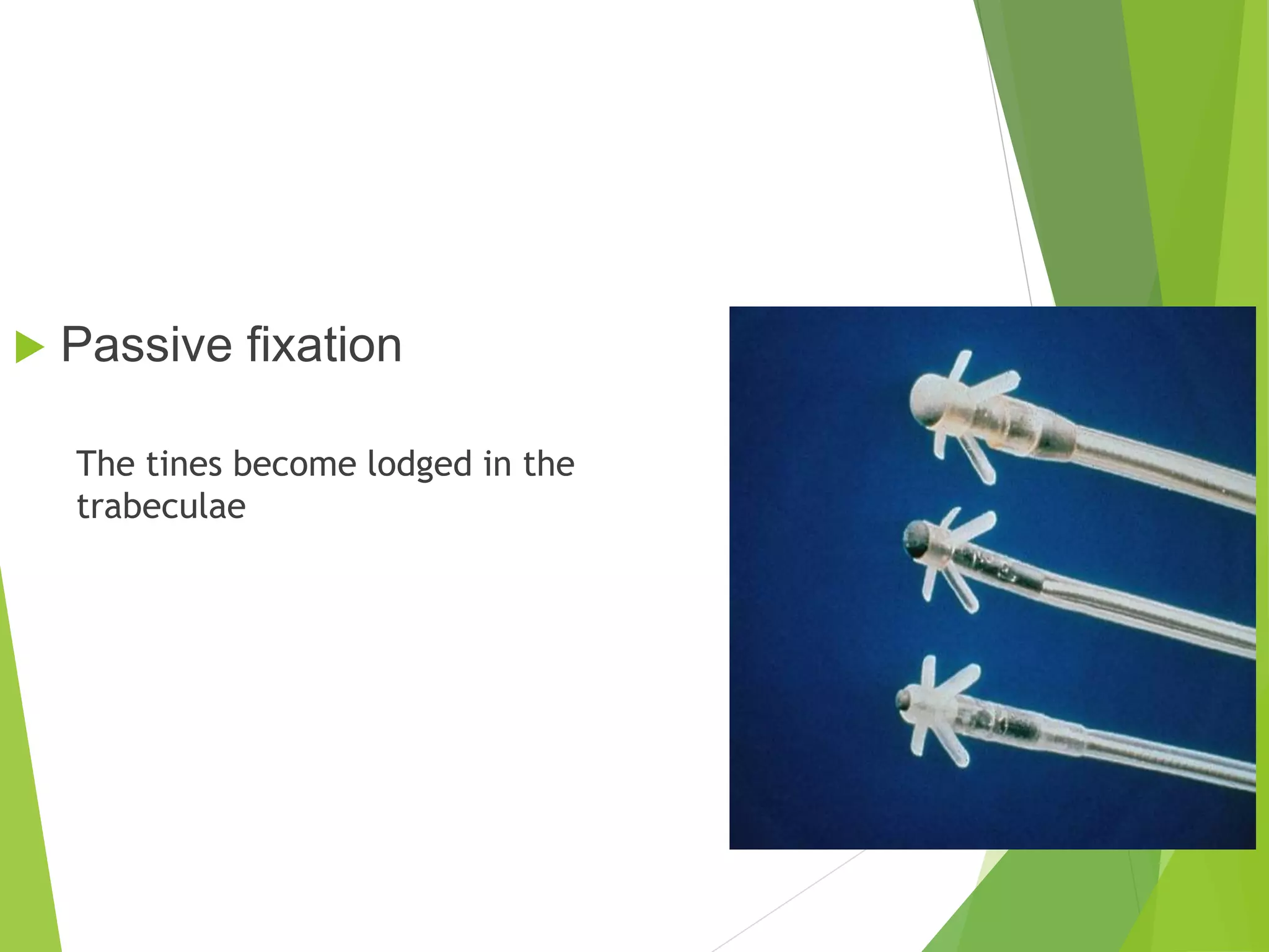
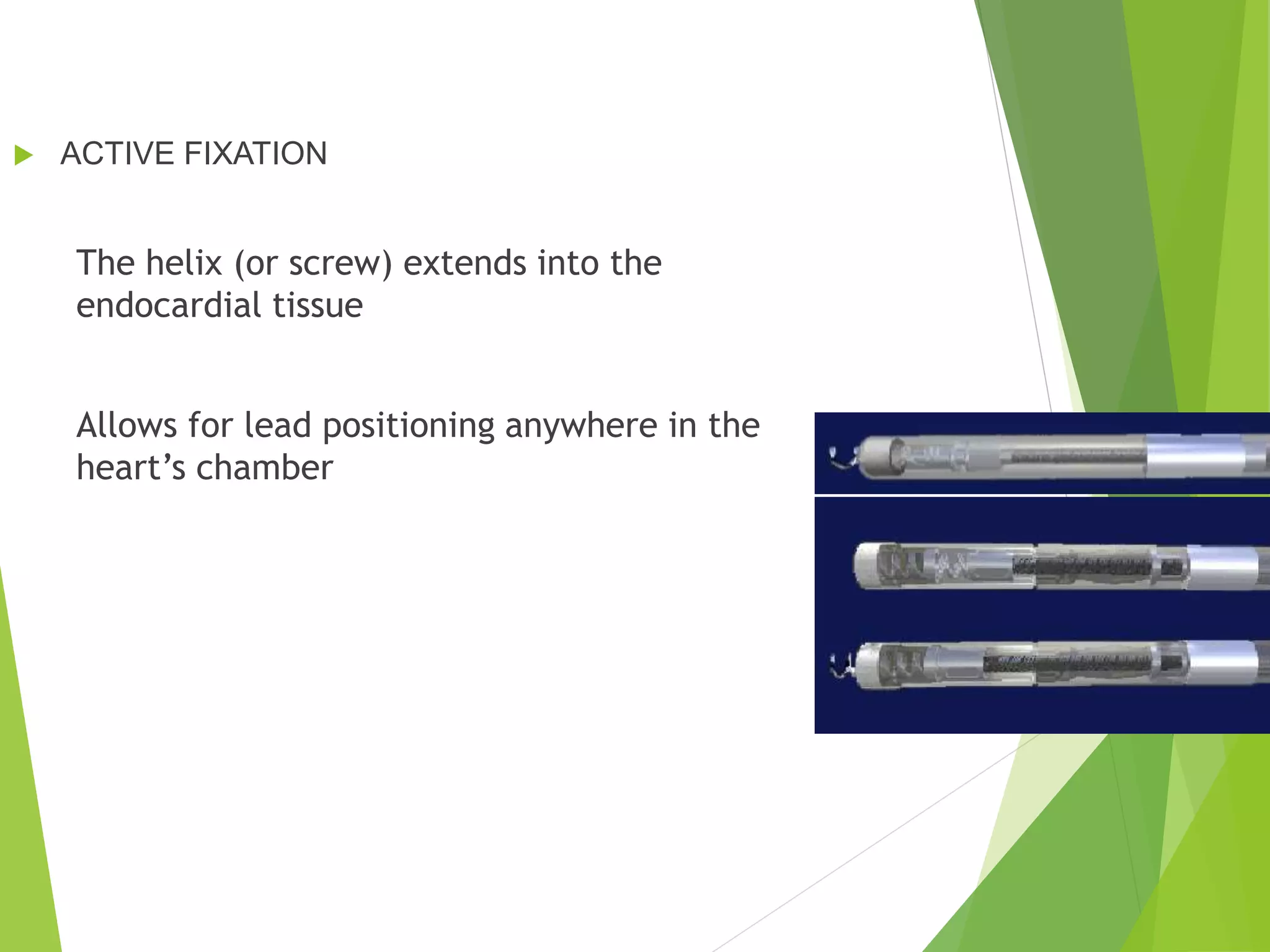
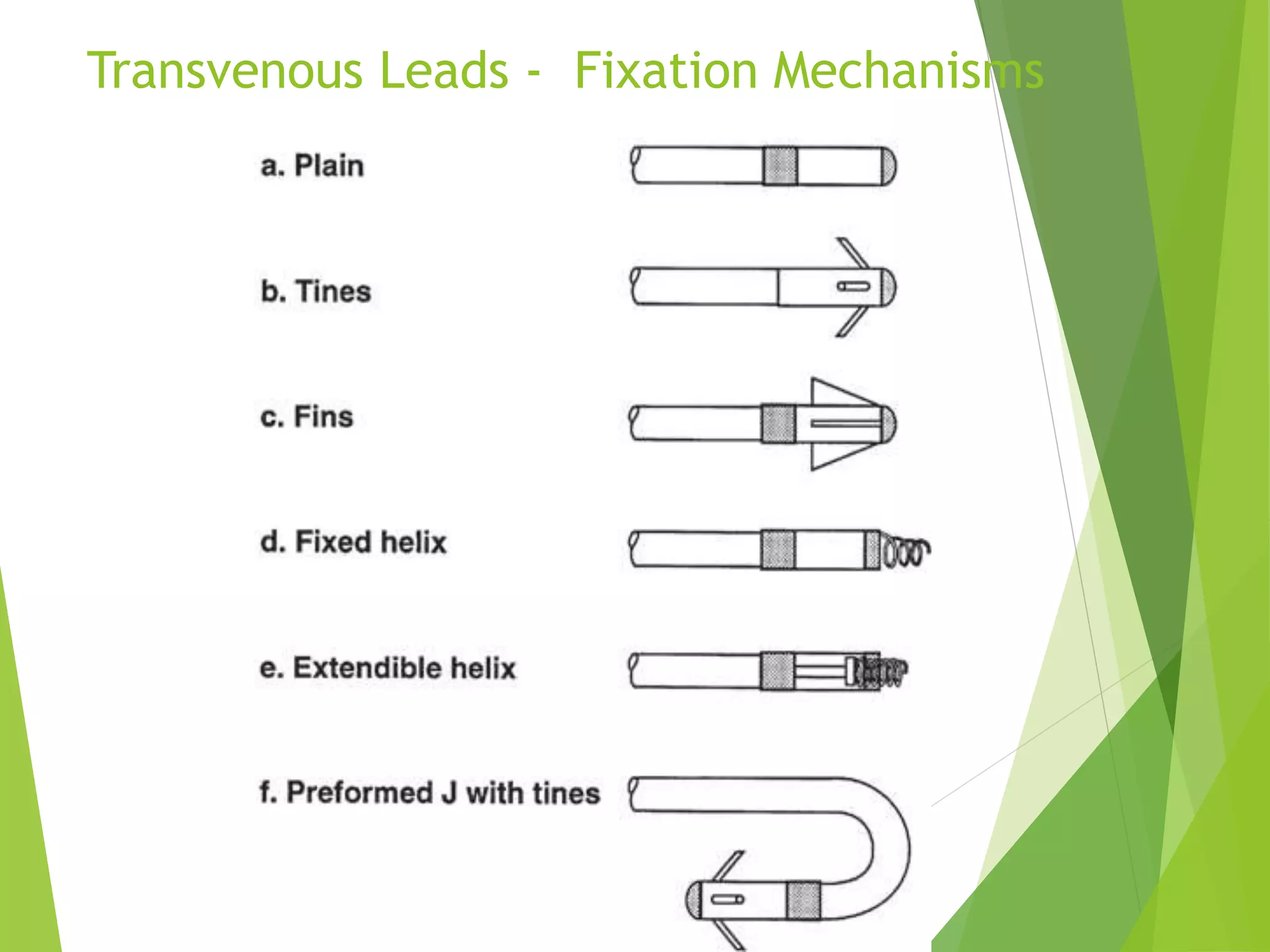
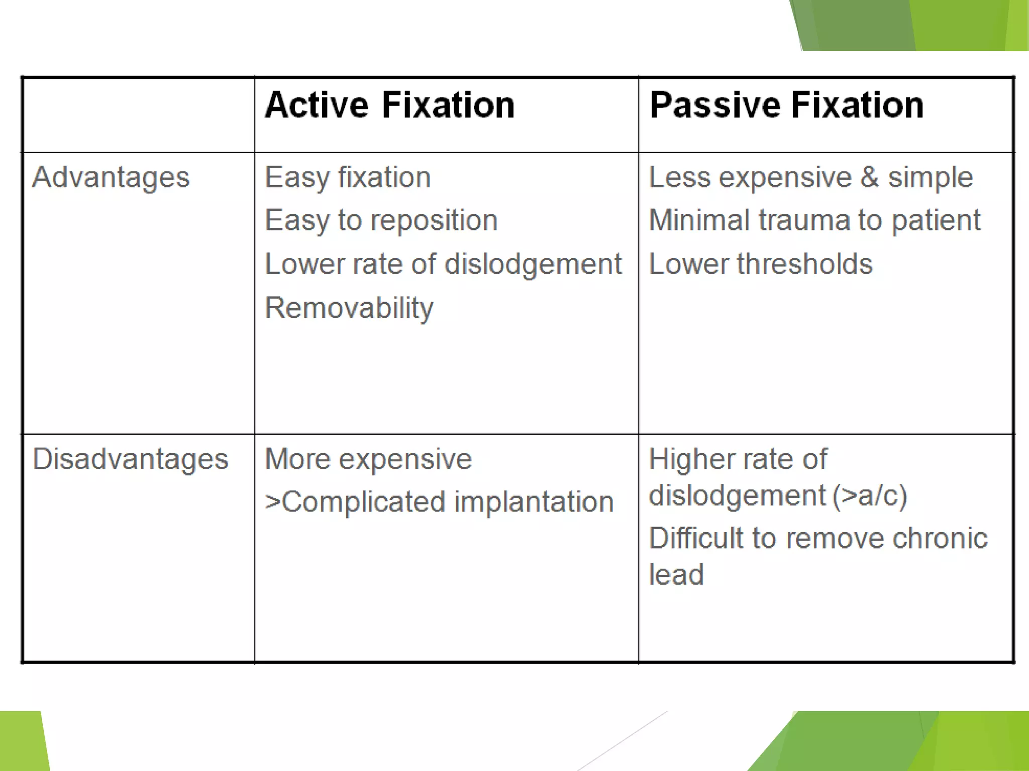
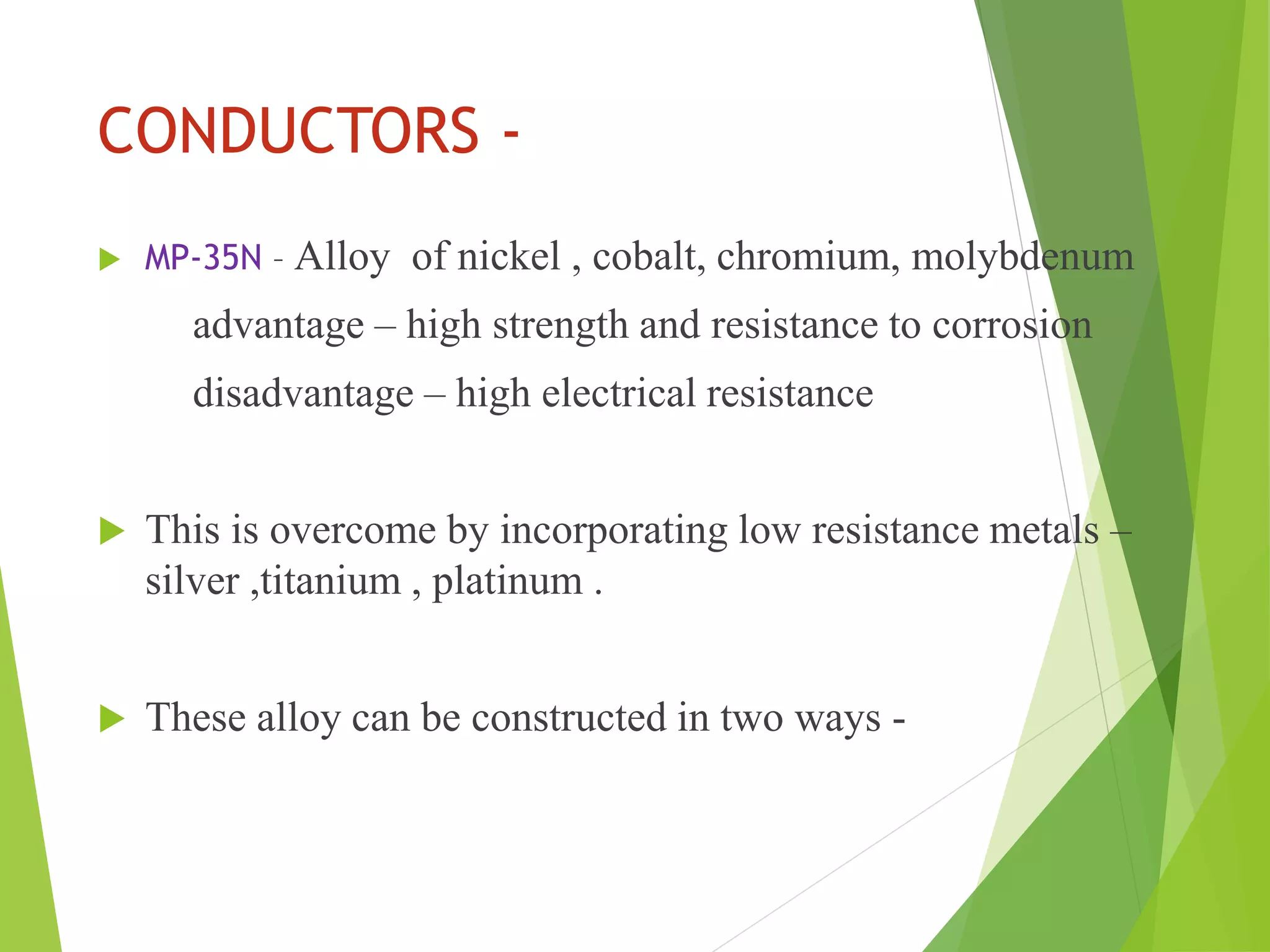
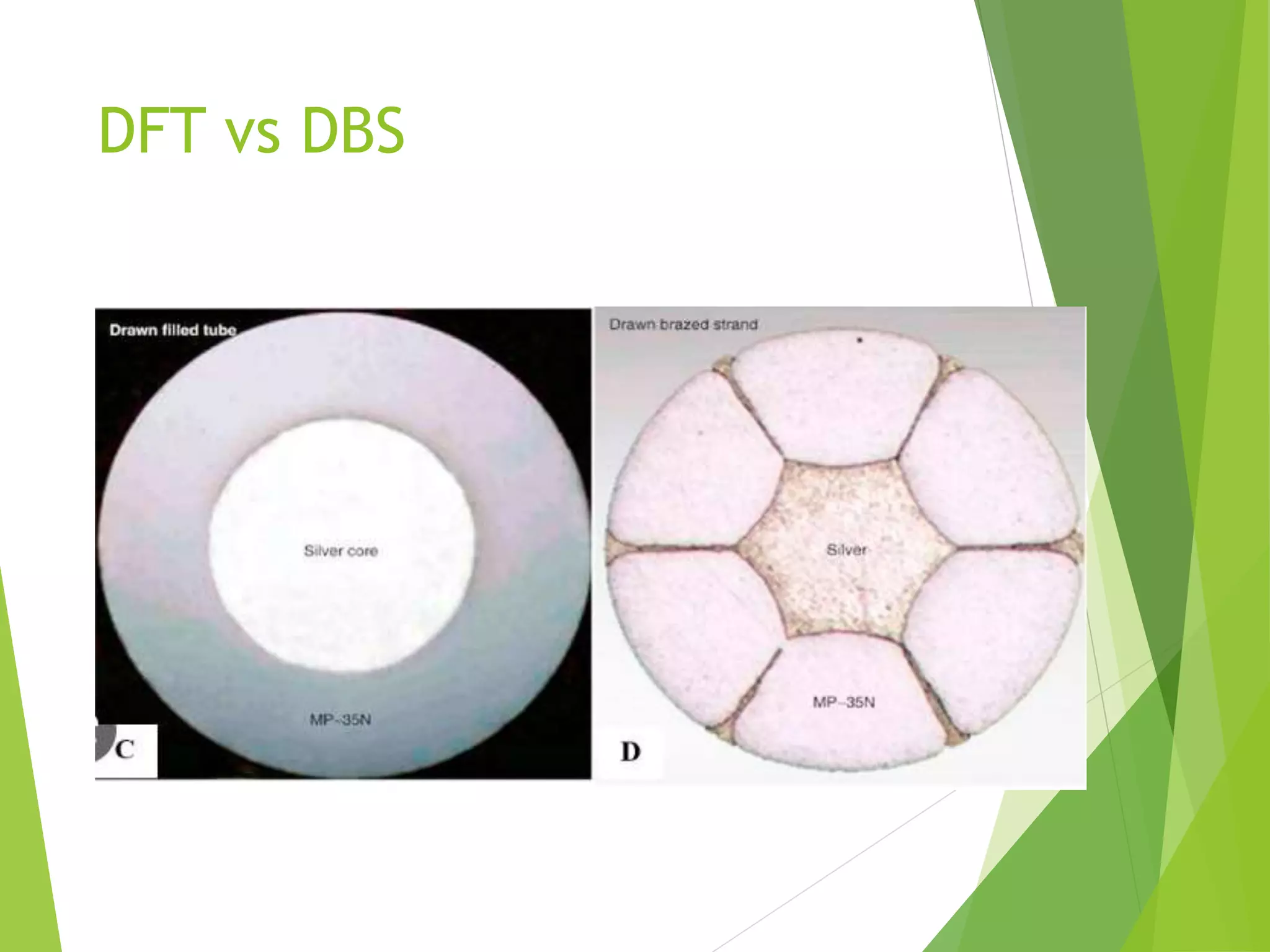
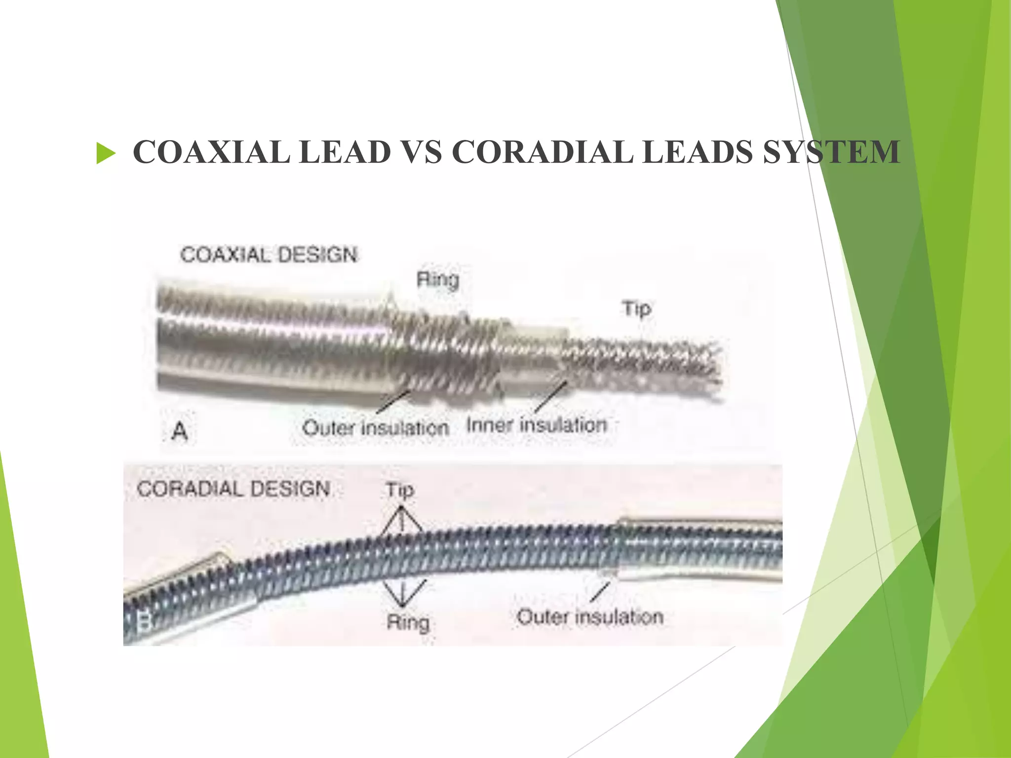


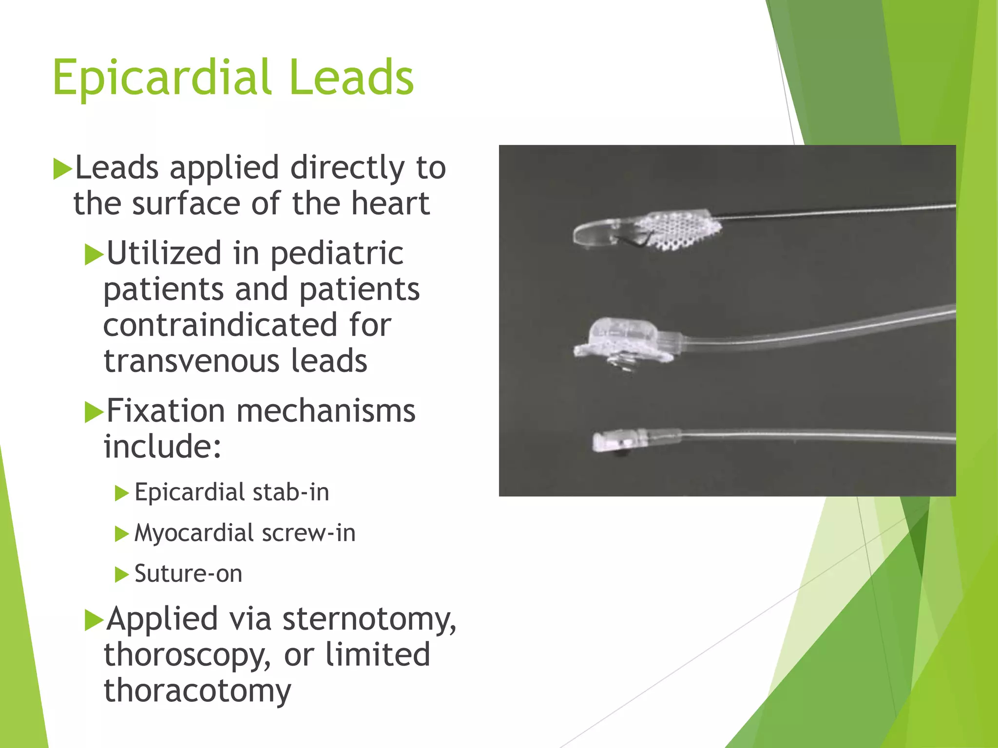
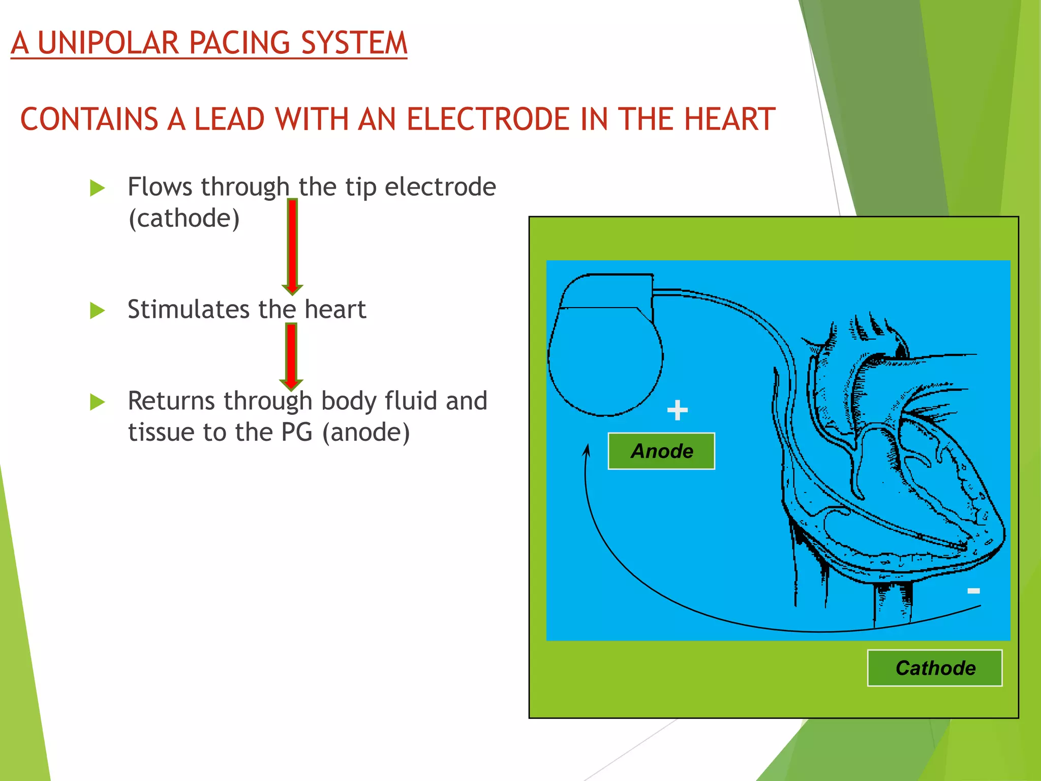
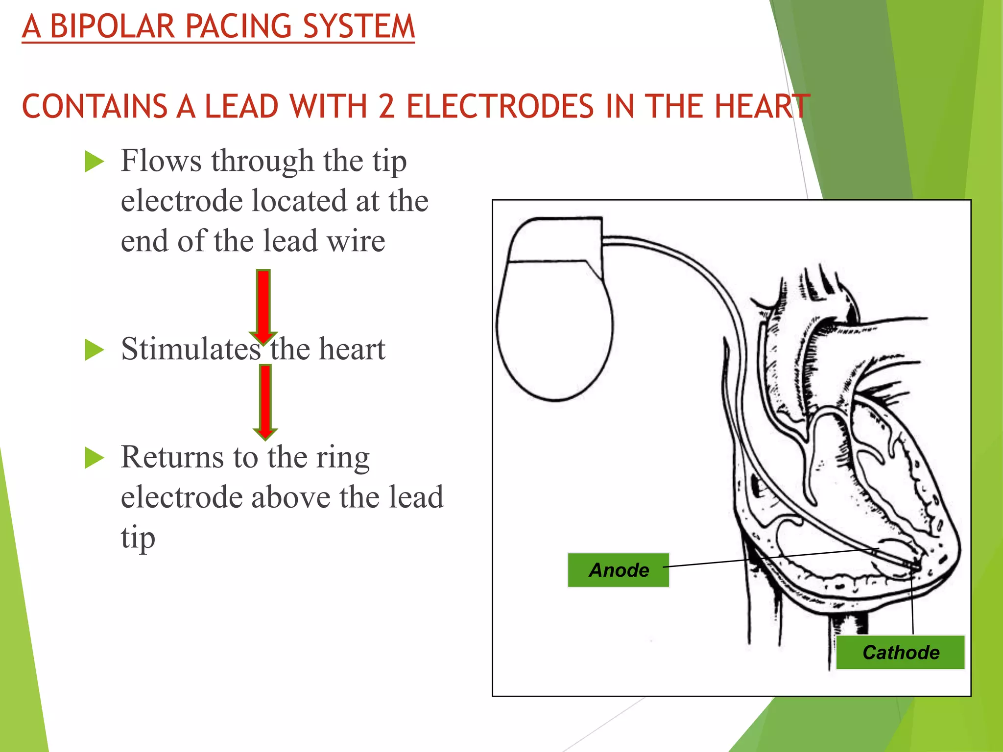
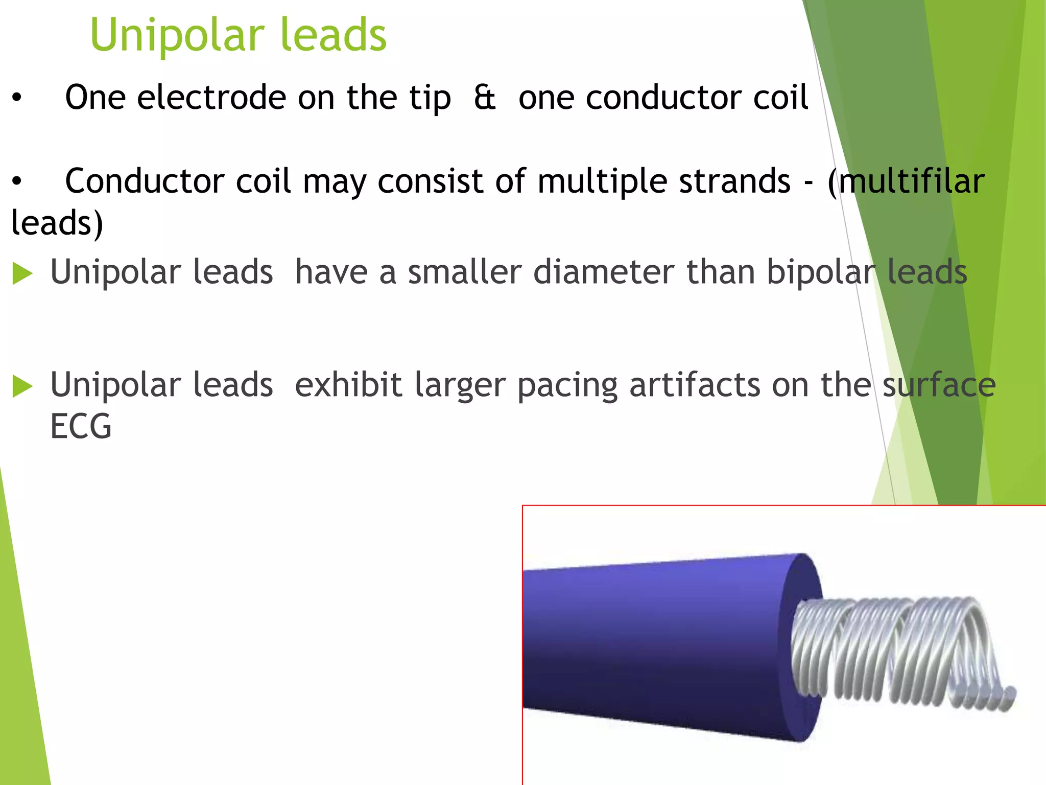

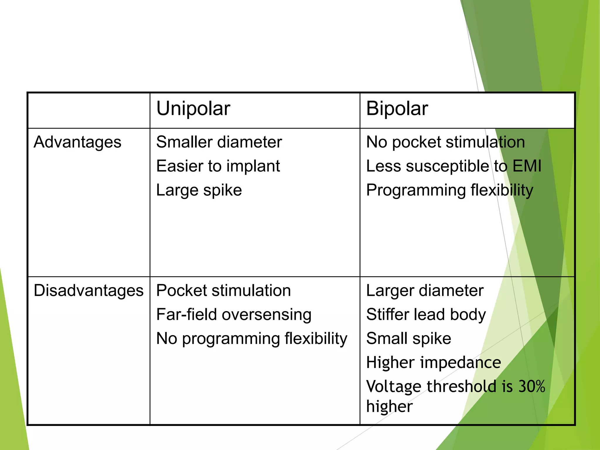
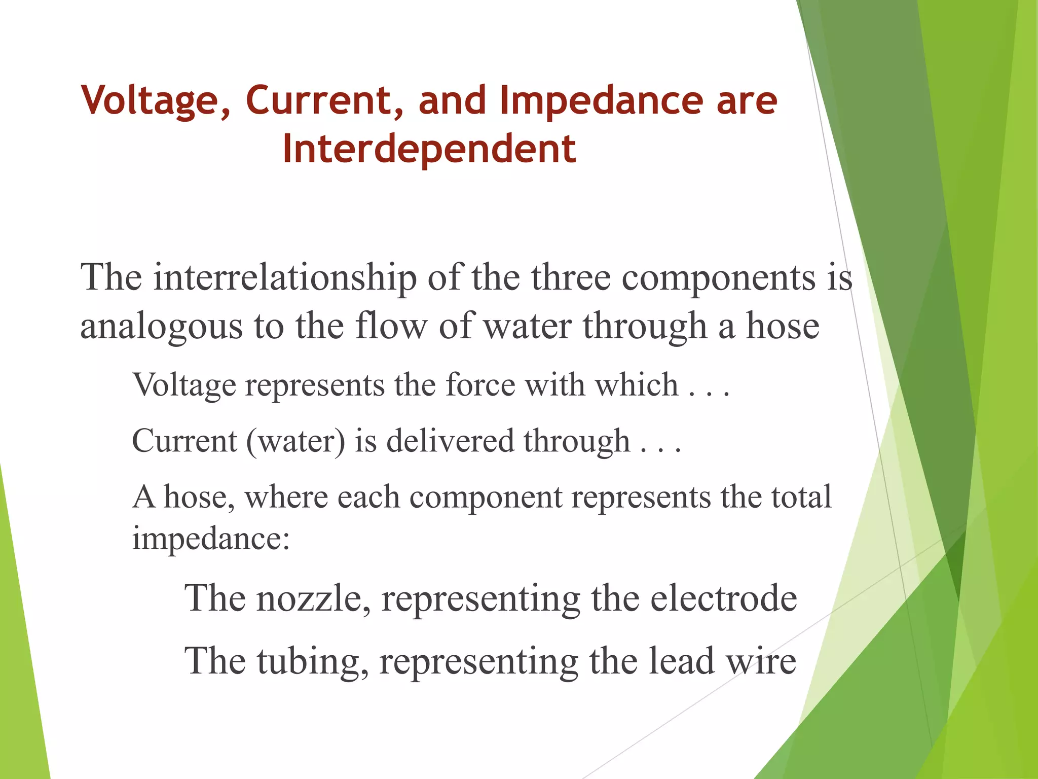
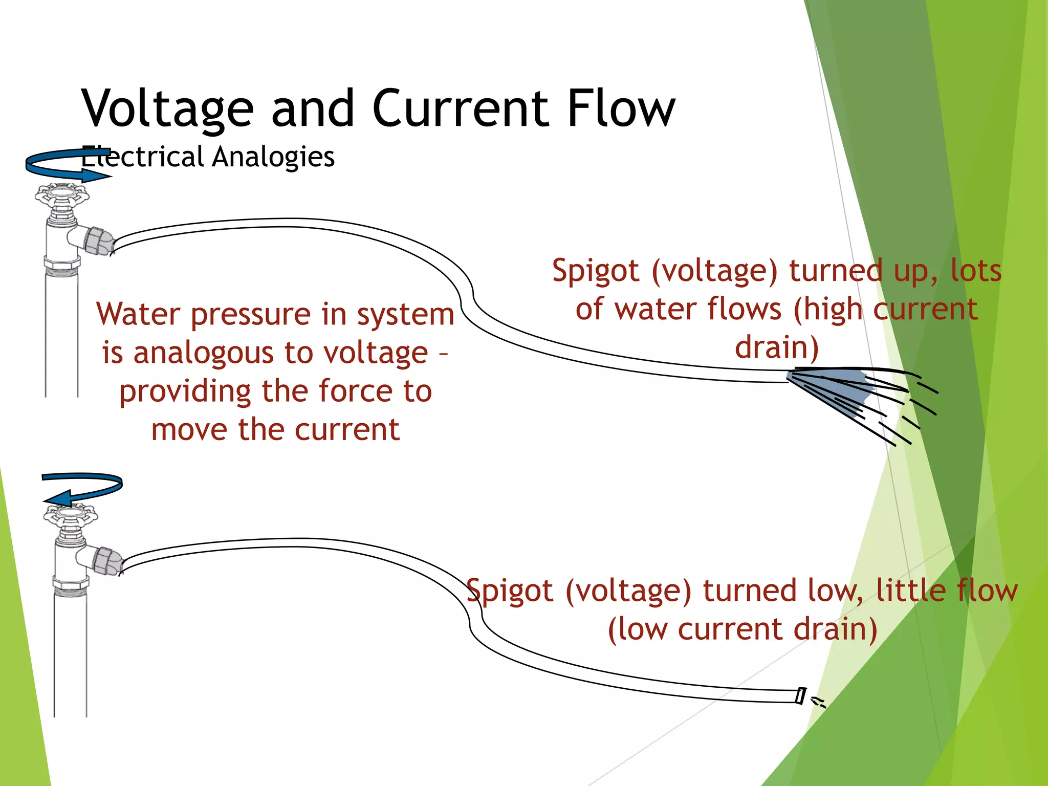
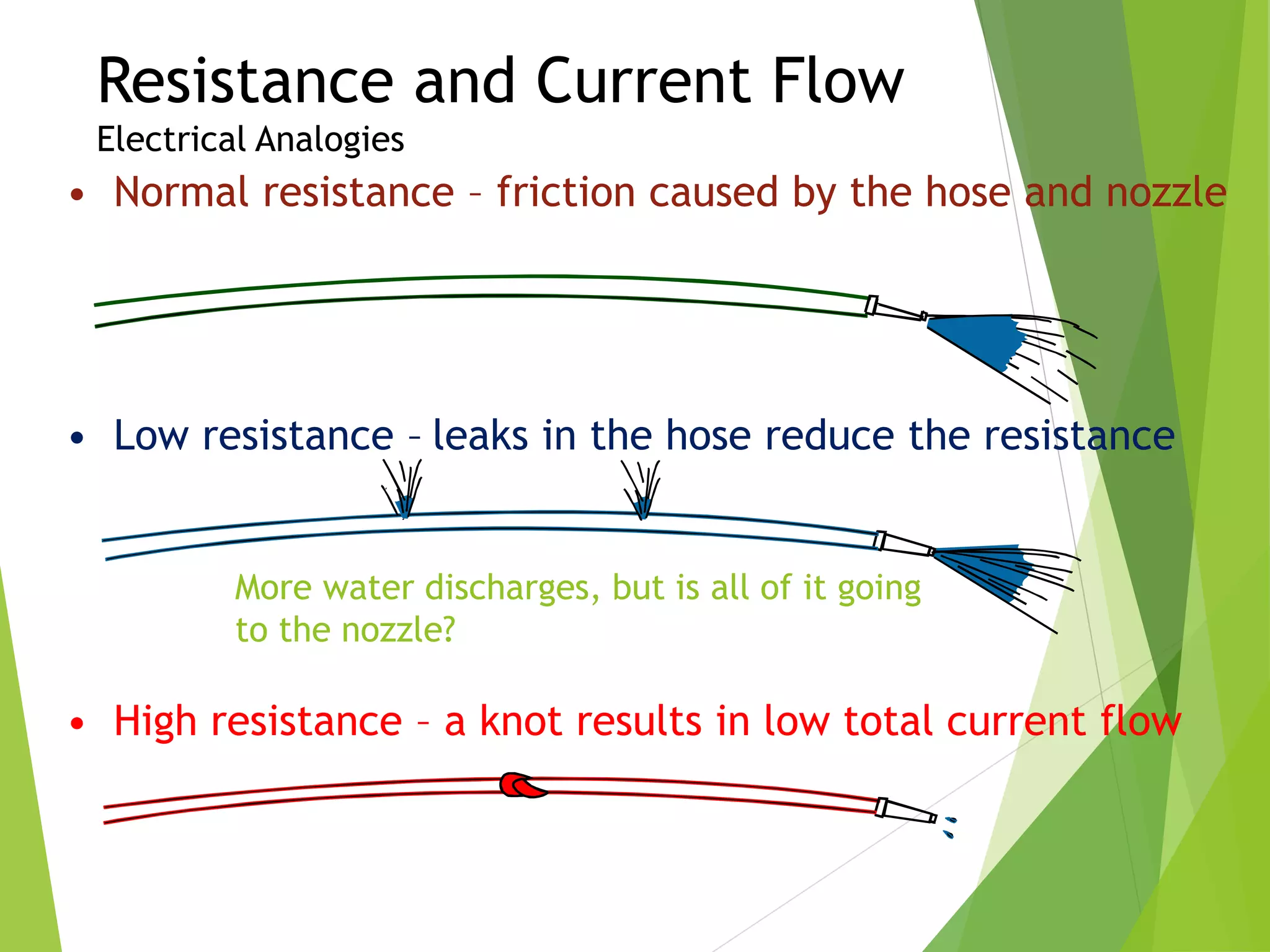
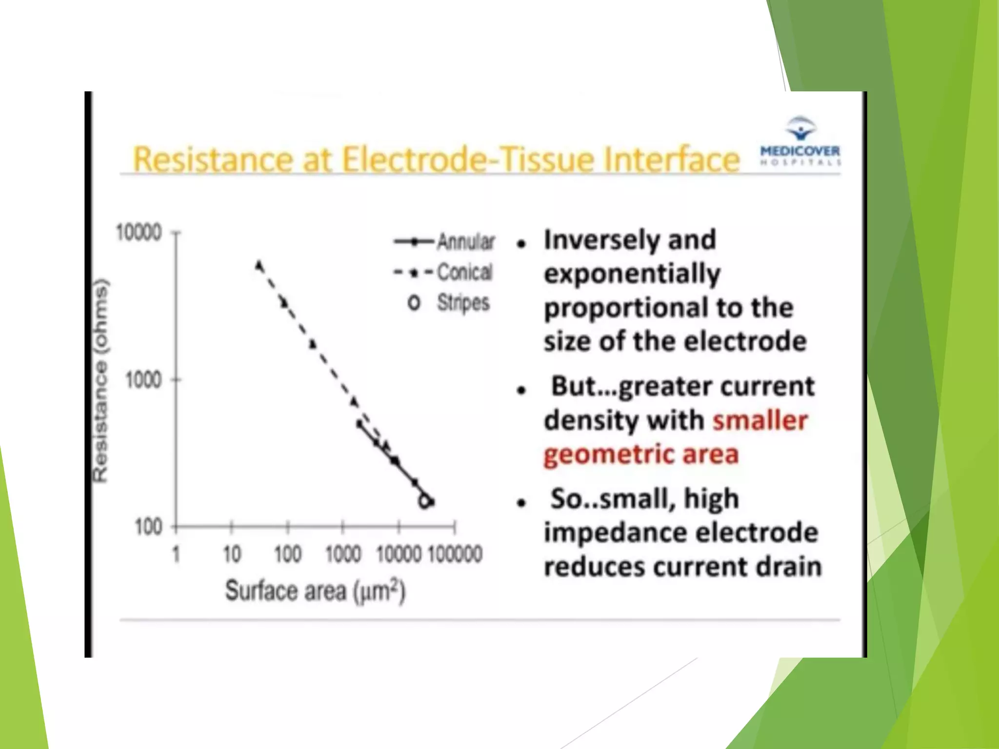
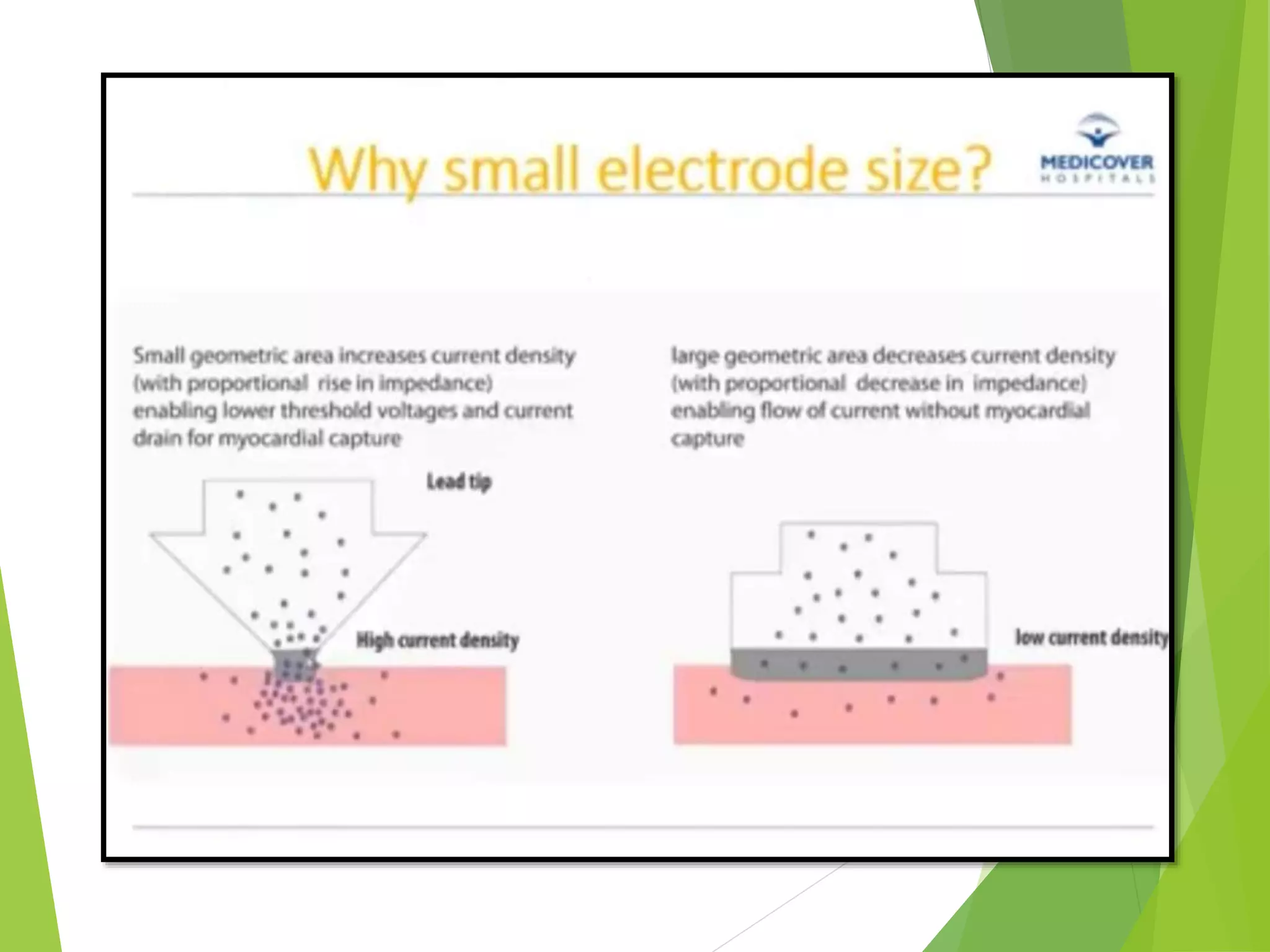
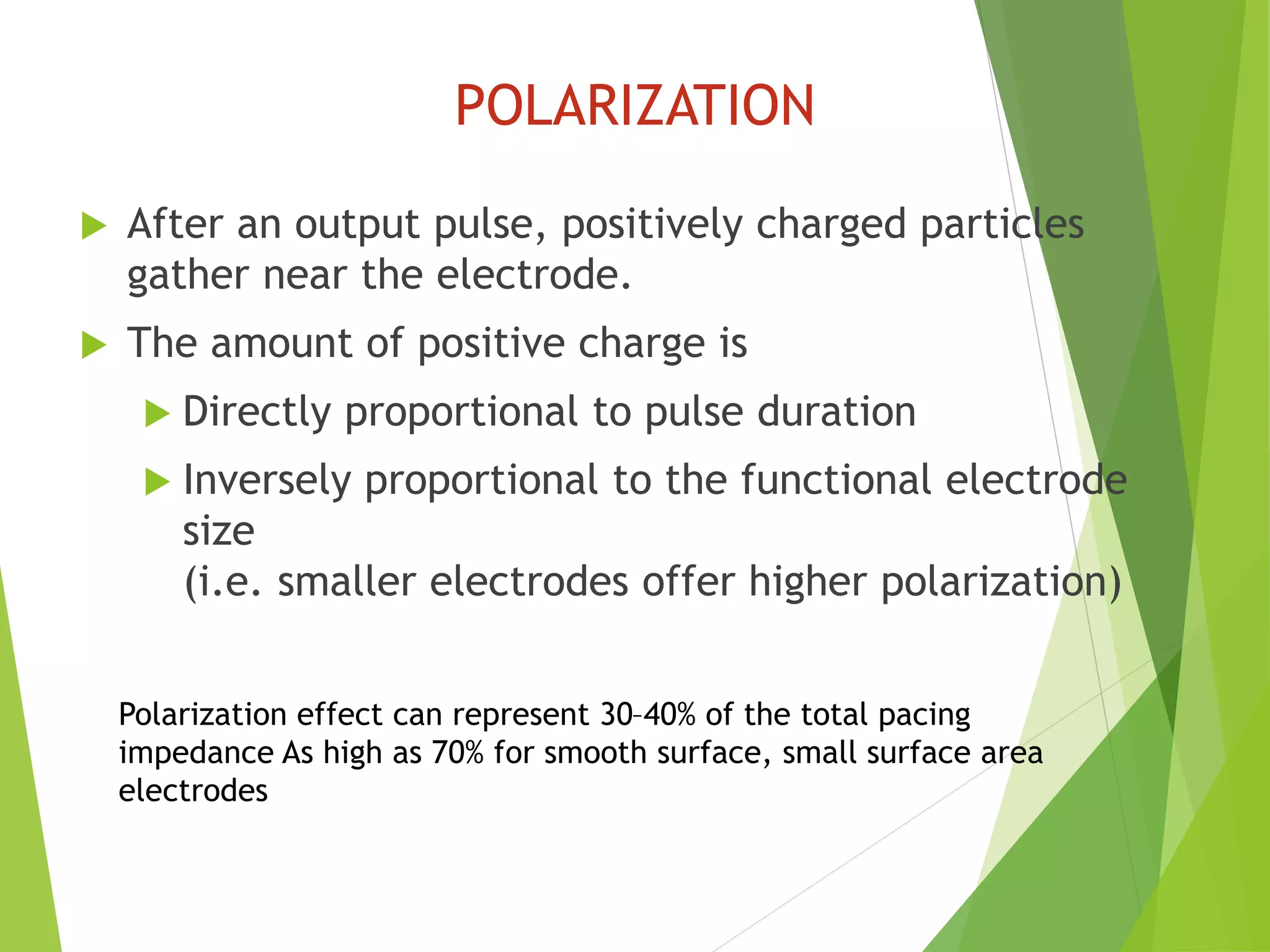
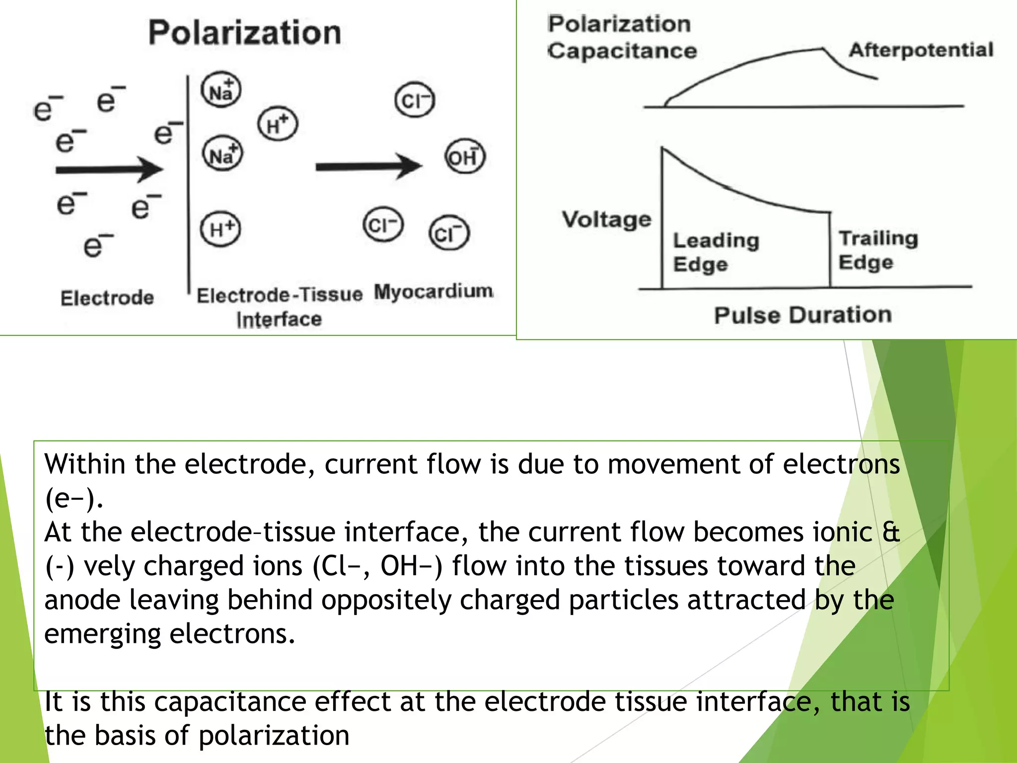

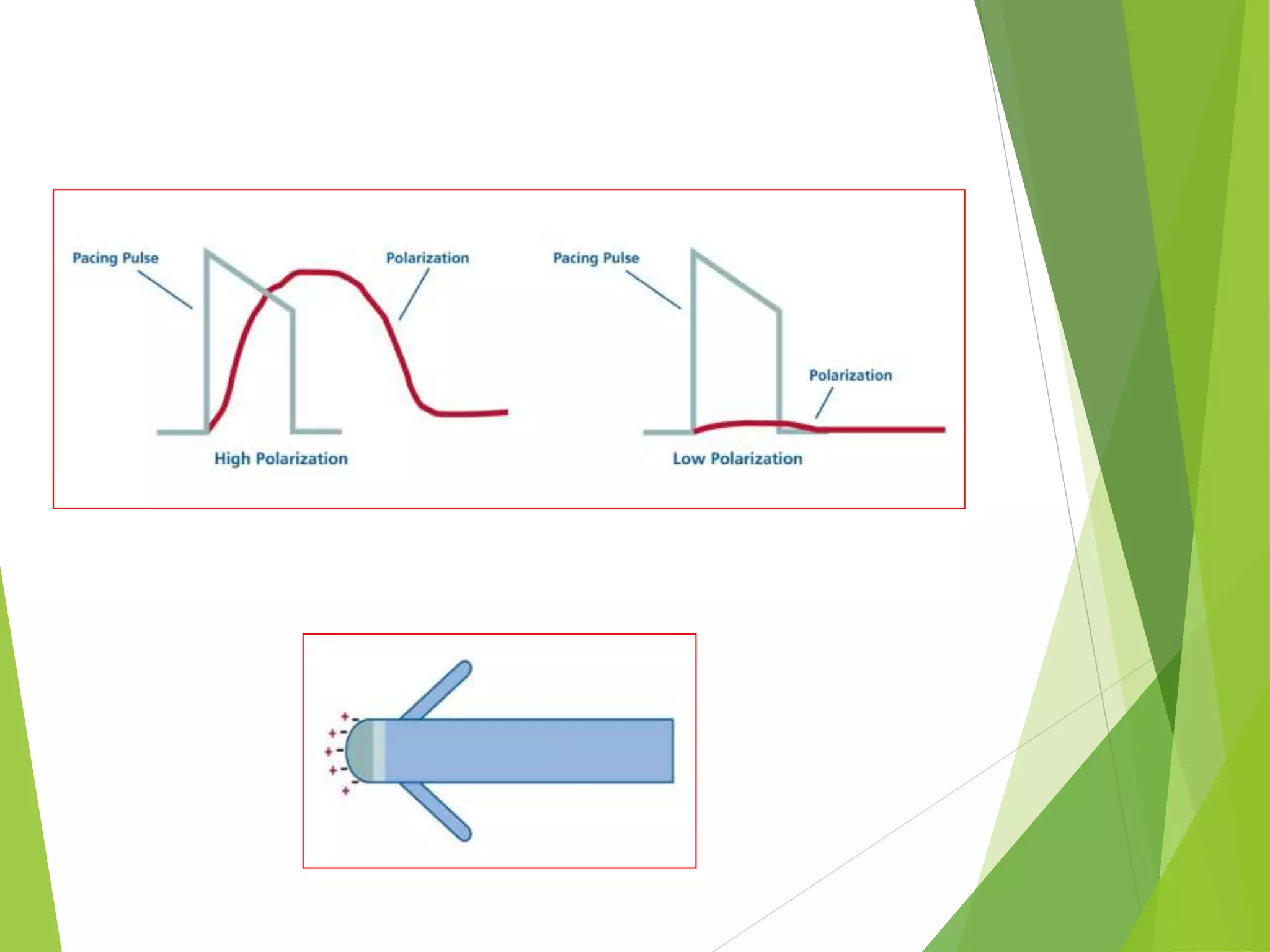


This document provides an overview of pacemaker basics and timing cycles. It discusses the components of a pacemaker circuit including the implantable pulse generator containing a battery and circuitry. It describes pacemaker leads which deliver electrical impulses from the pulse generator to the heart. The document outlines characteristics of pacemaker leads including fixation mechanisms, insulation materials, and polarity. It also discusses concepts such as stimulation threshold, polarization, impedance, and how these factors interact based on Ohm's law relationships.