This document provides an overview of cardiac pacemakers, including:
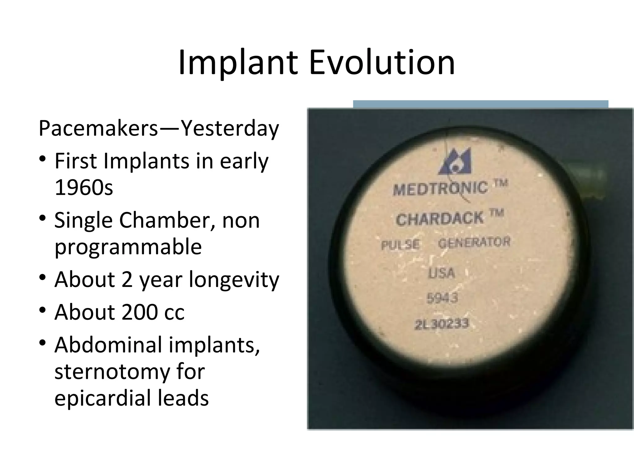
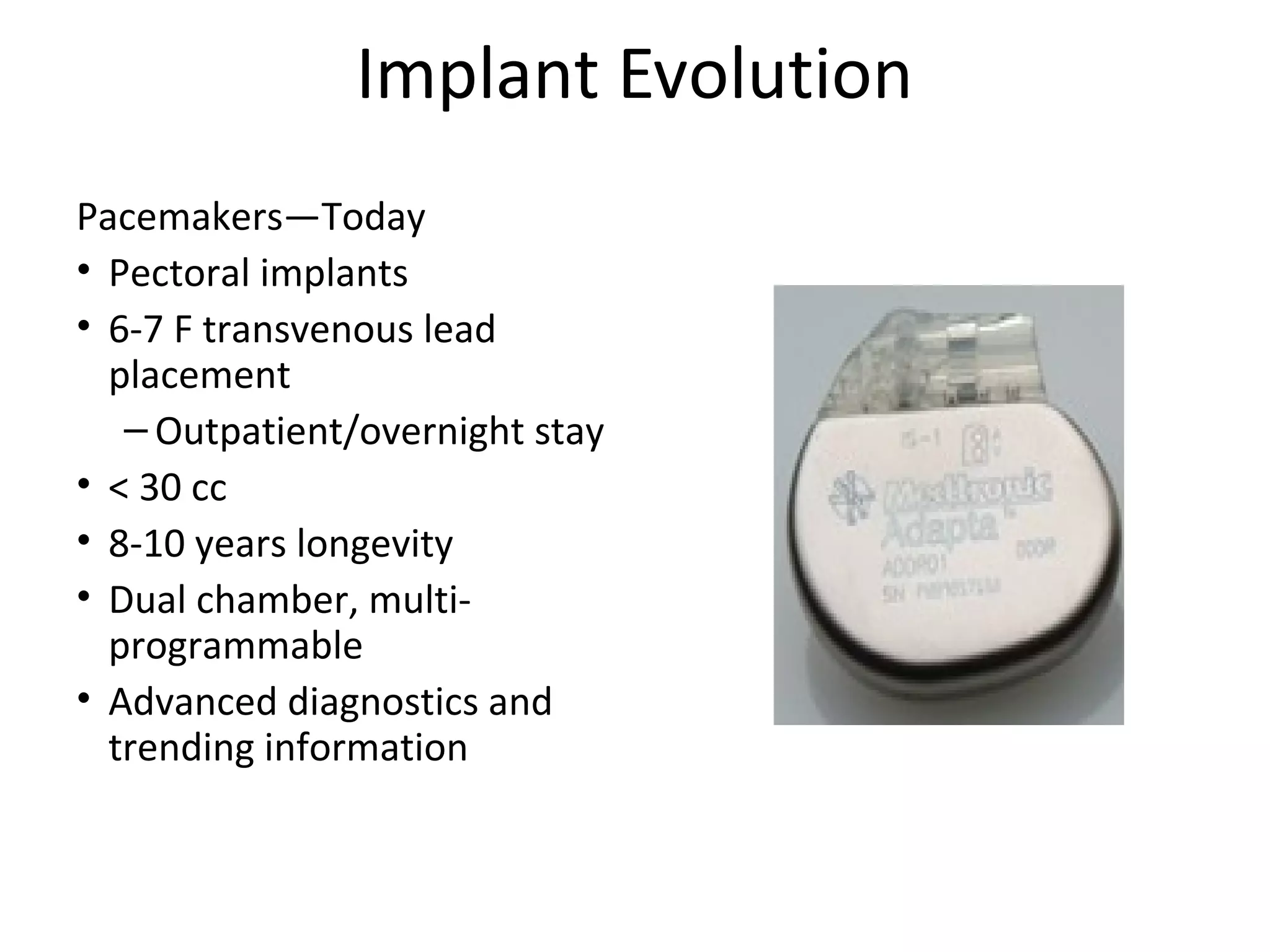
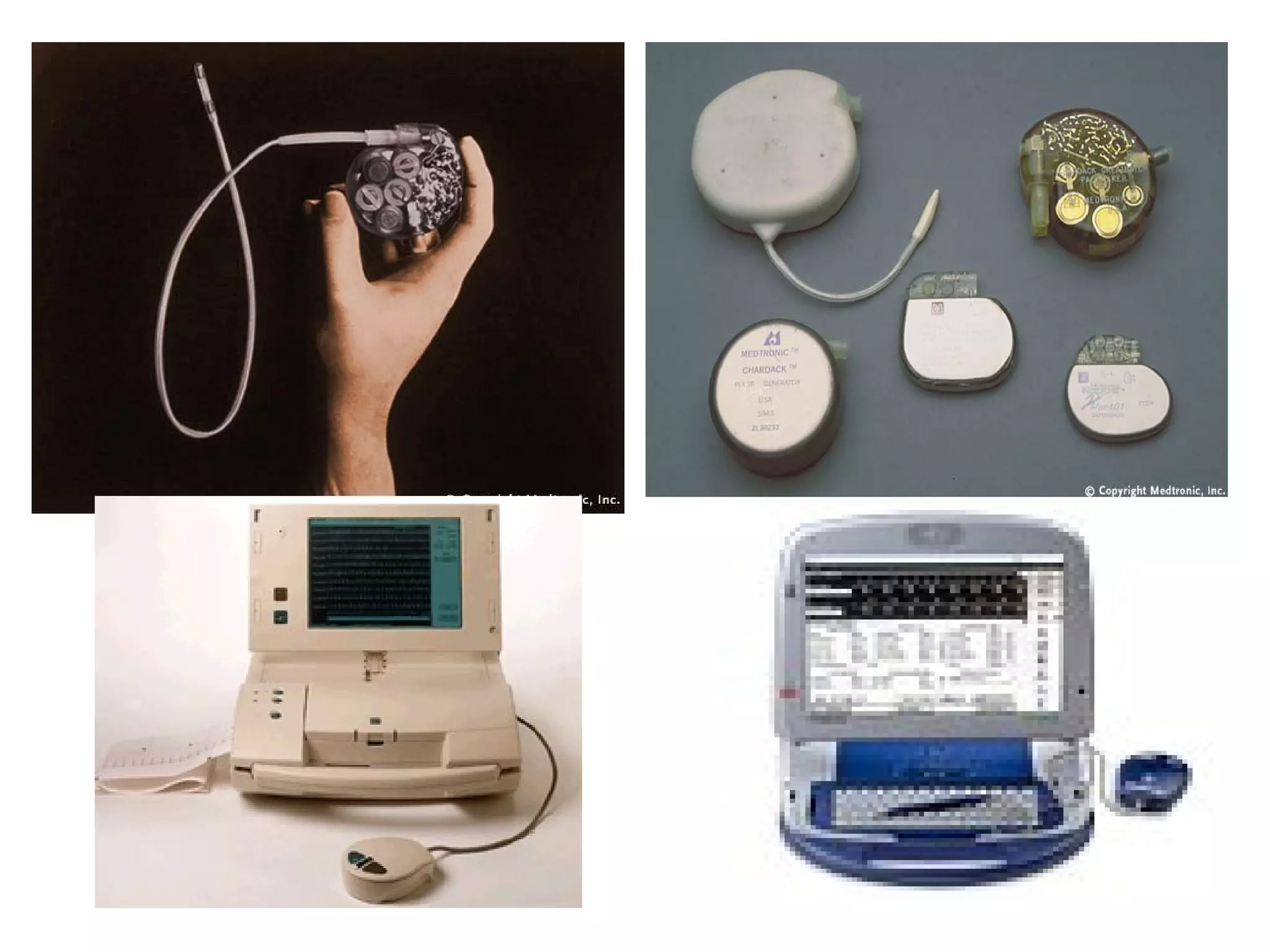
- A brief history of the development of pacemakers from the first implant in 1958 to modern devices.
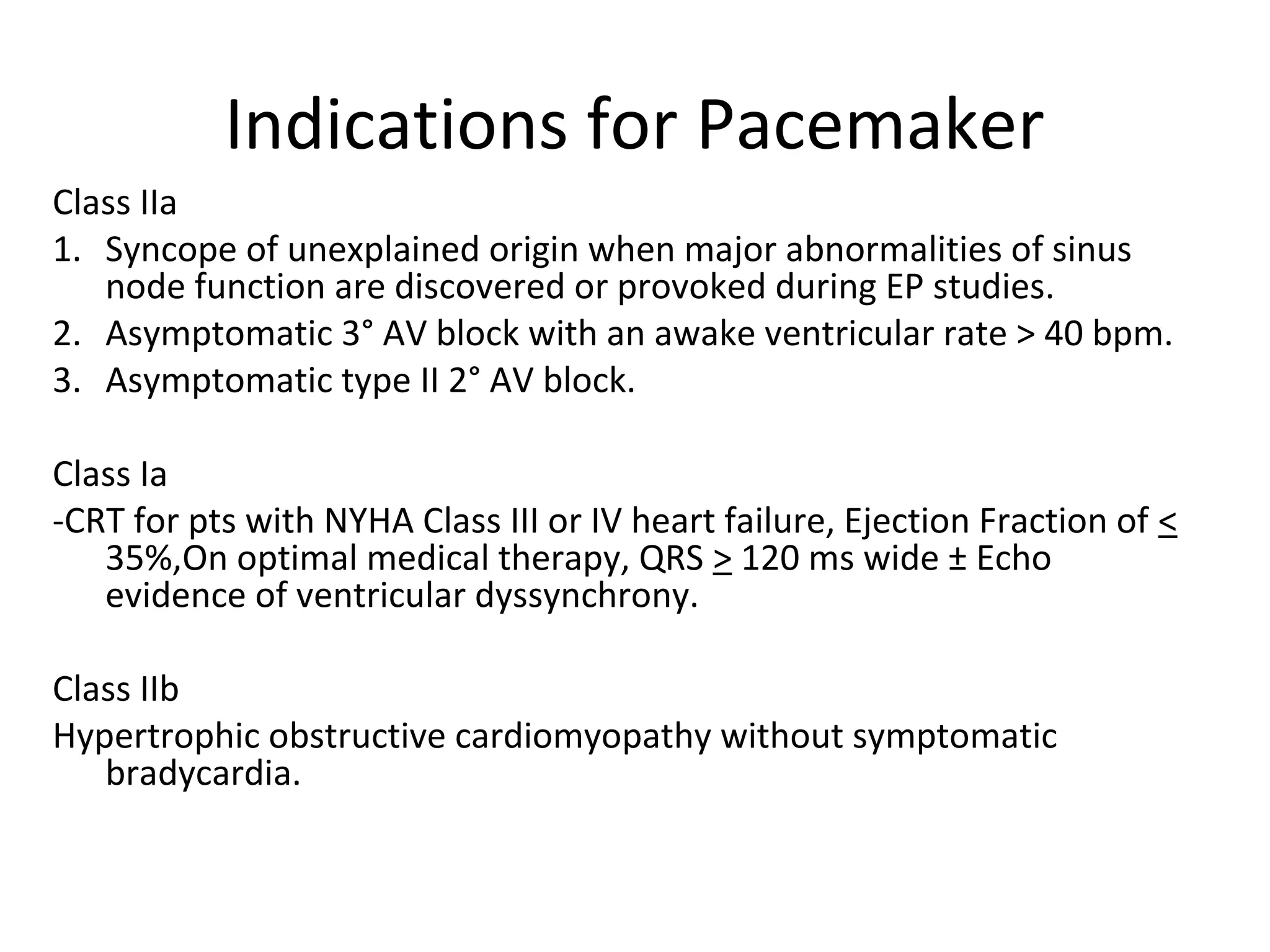
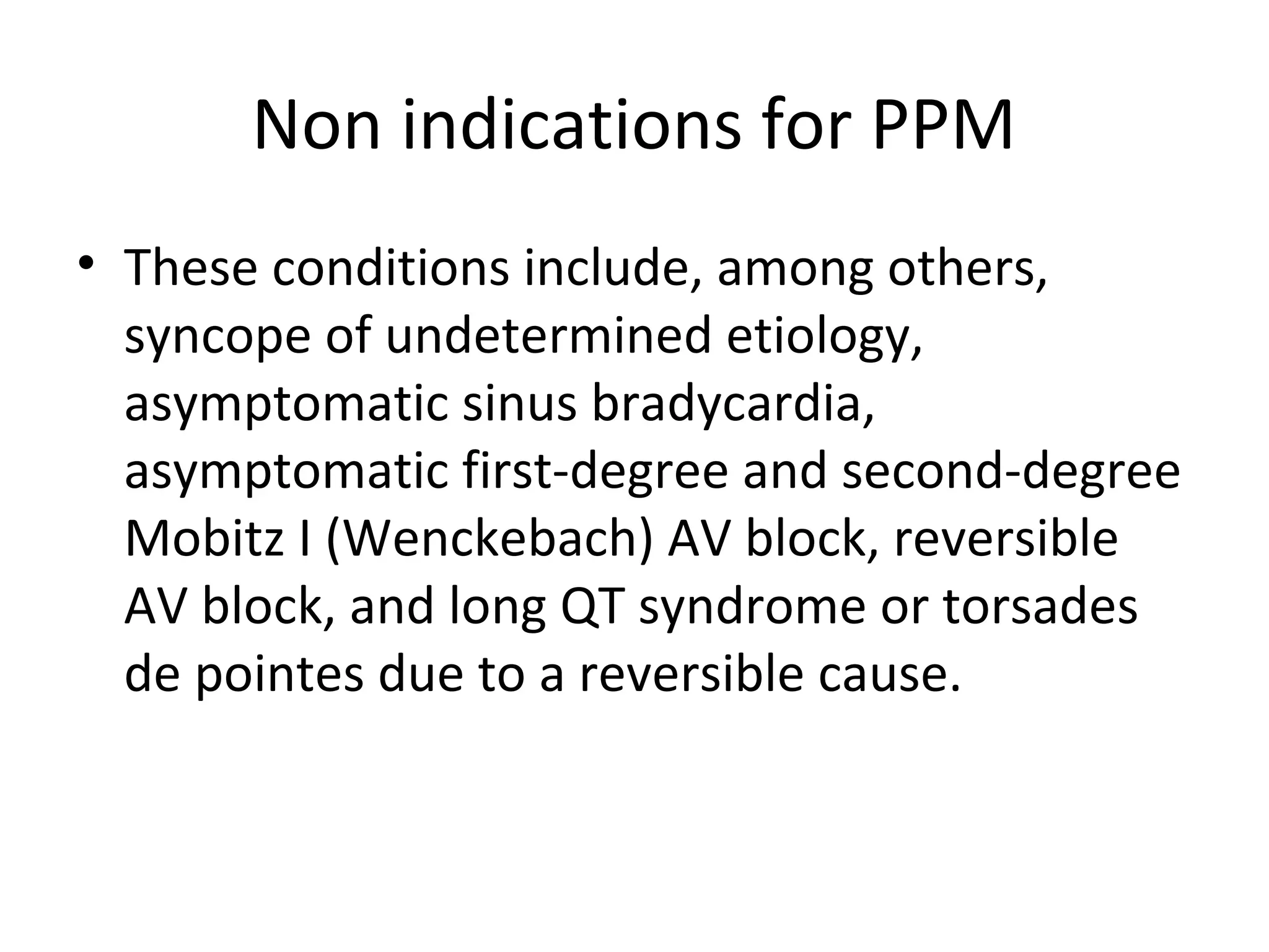
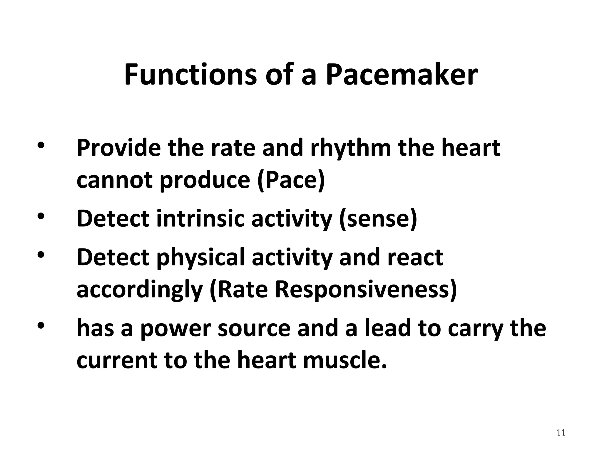
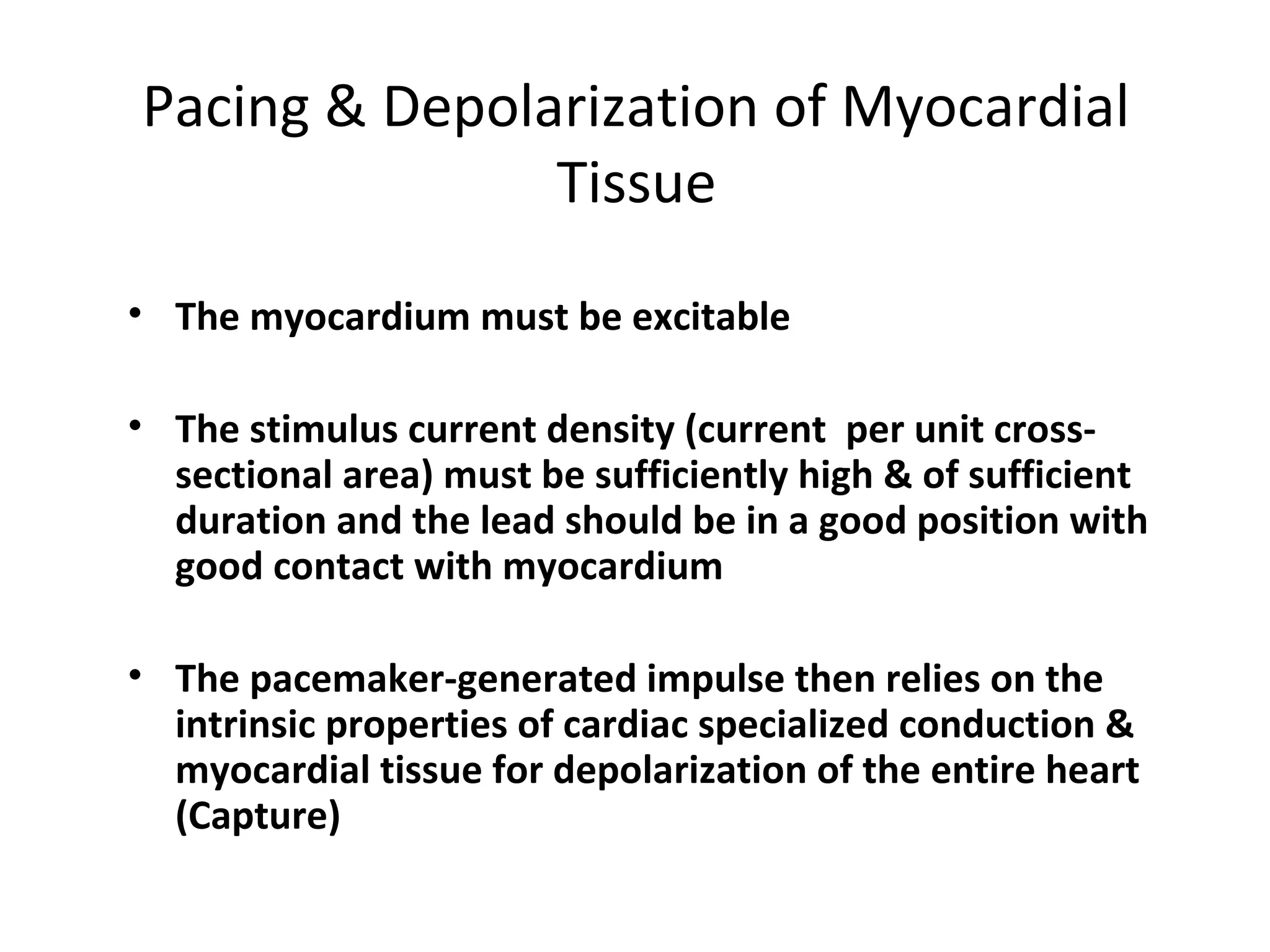
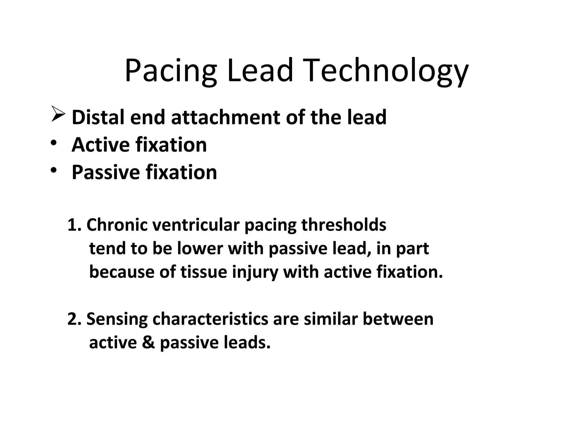
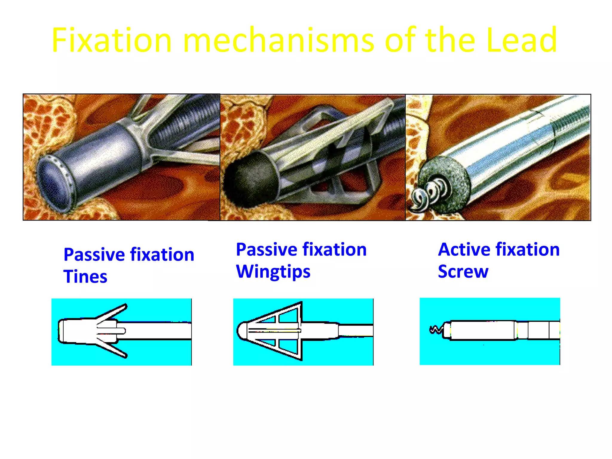
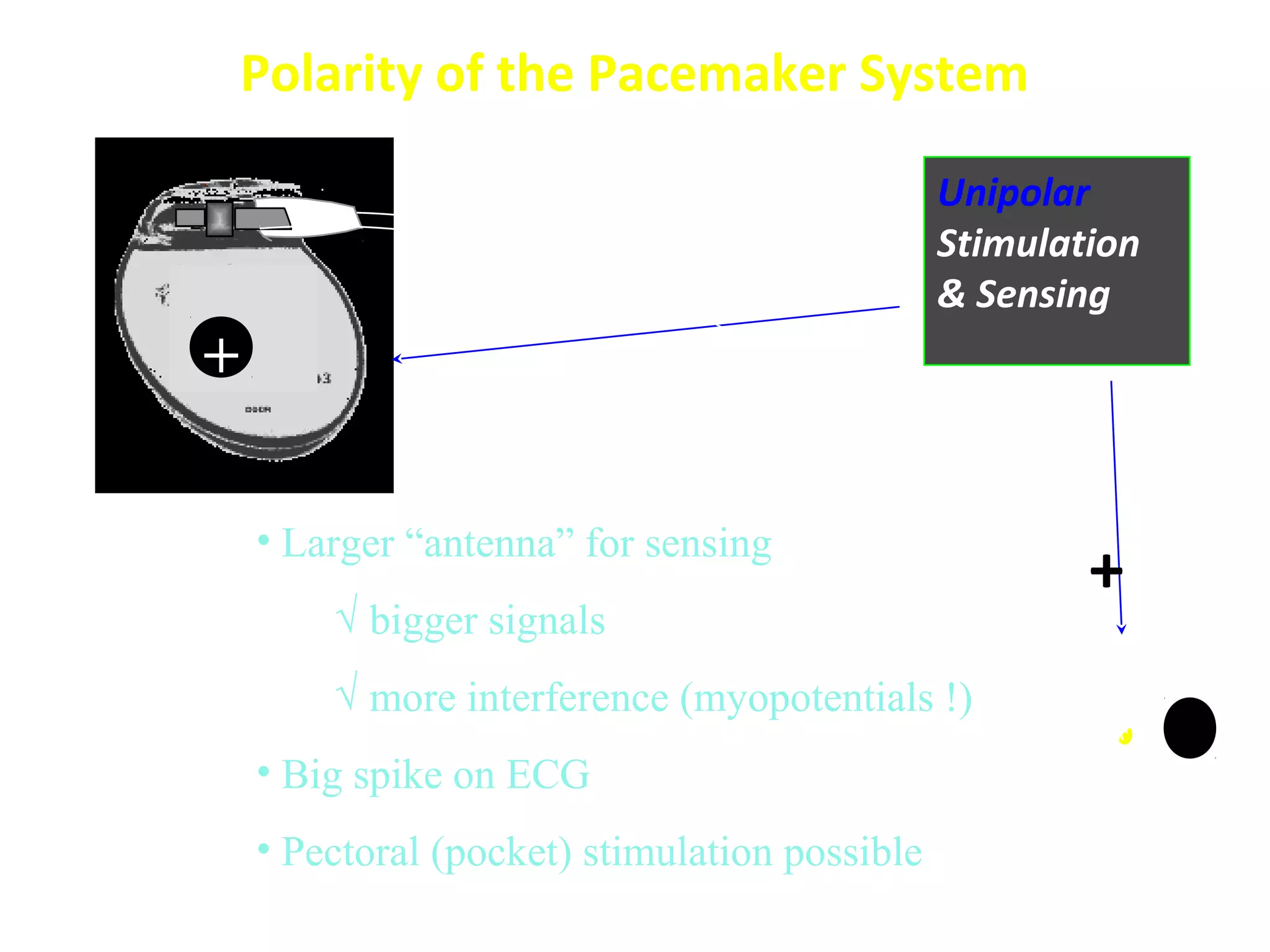
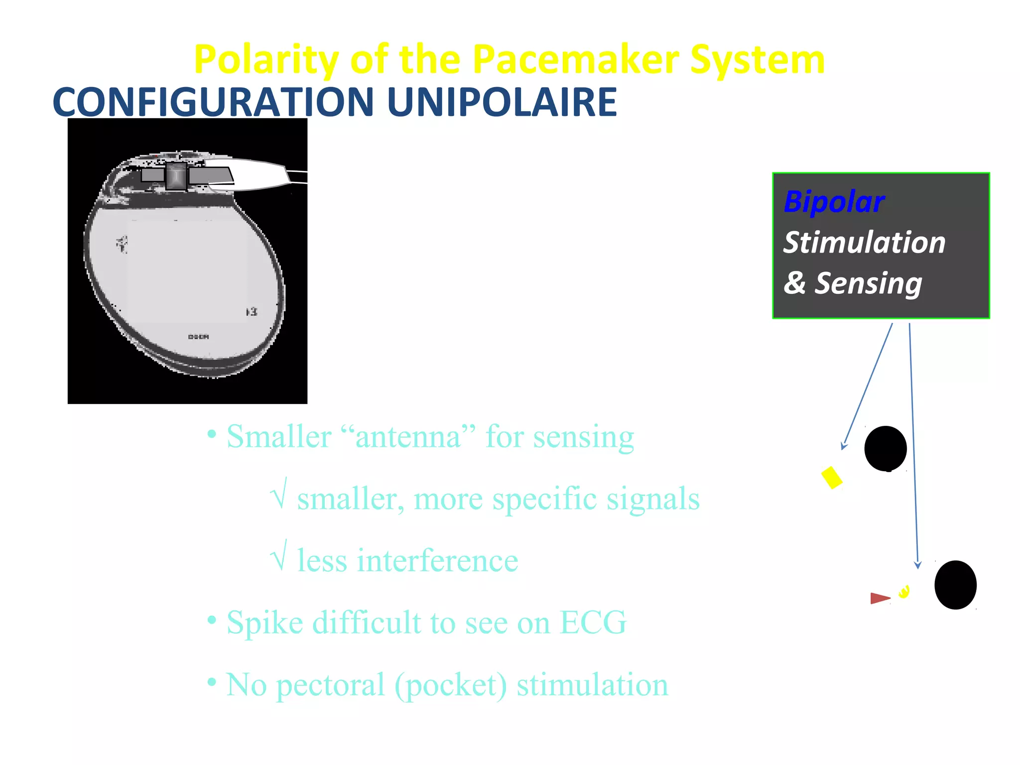
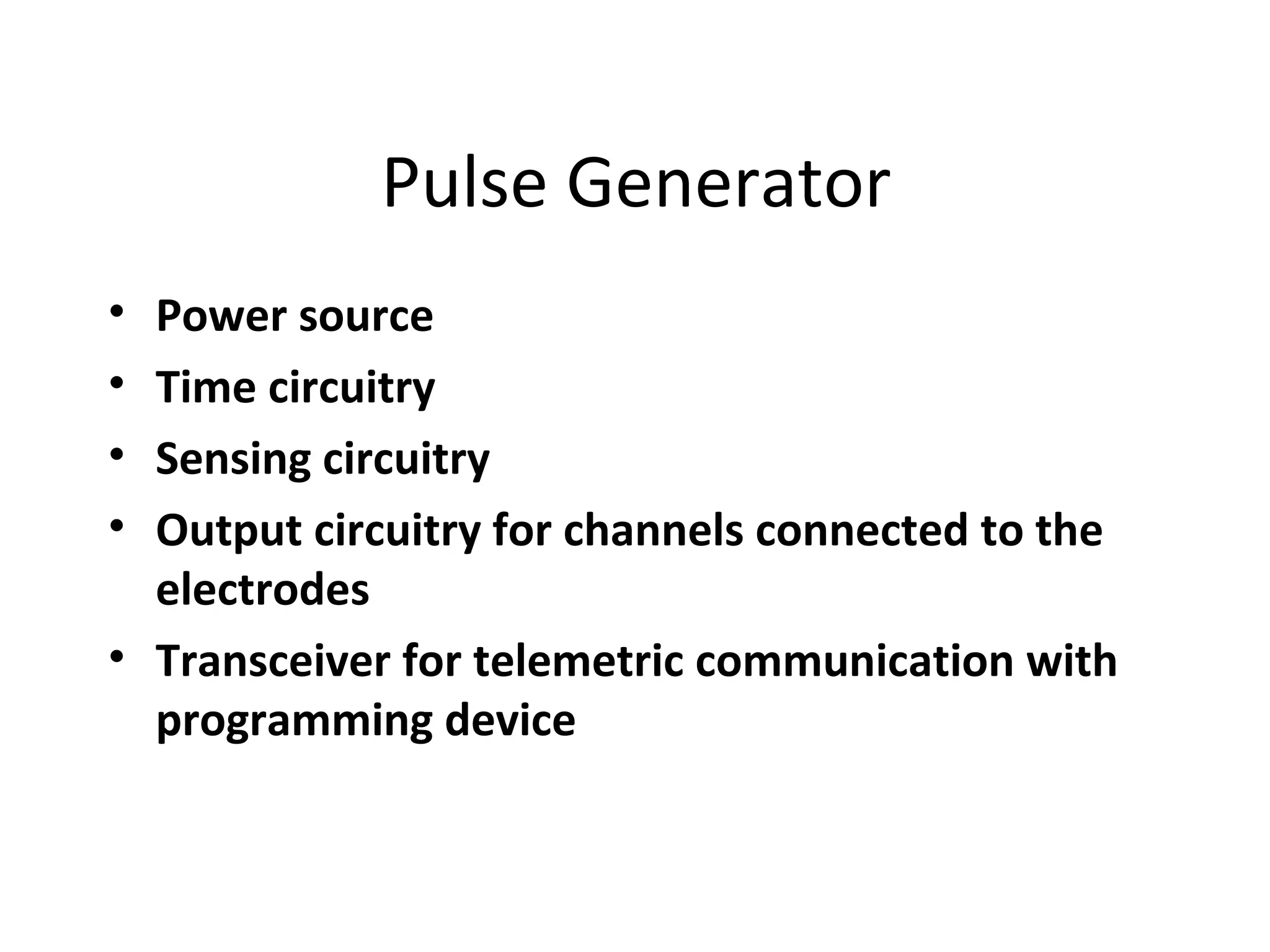
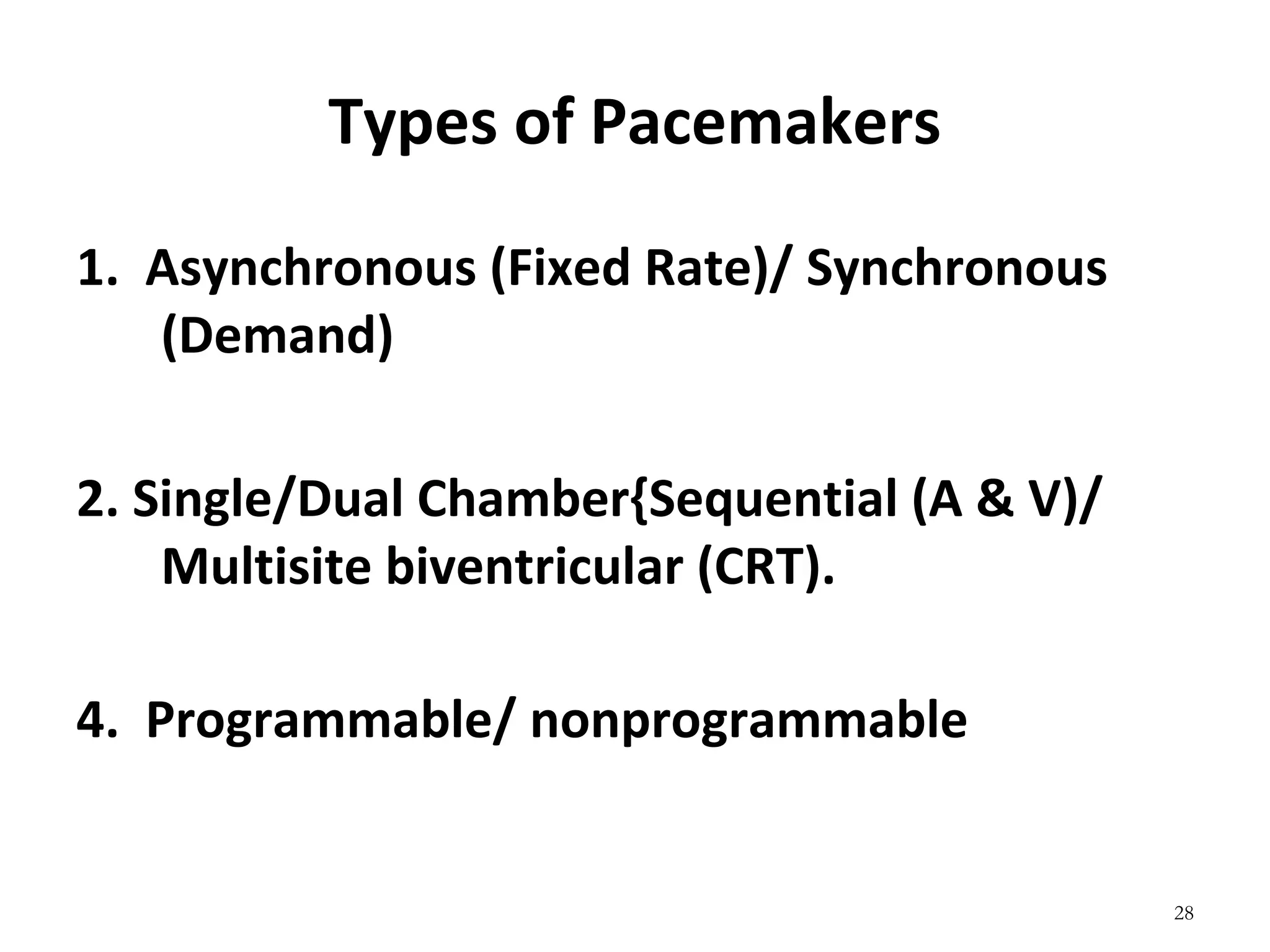
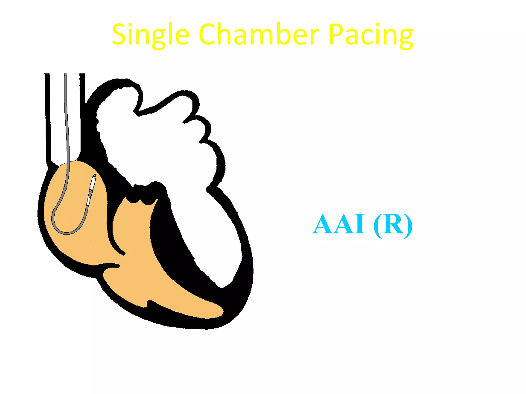
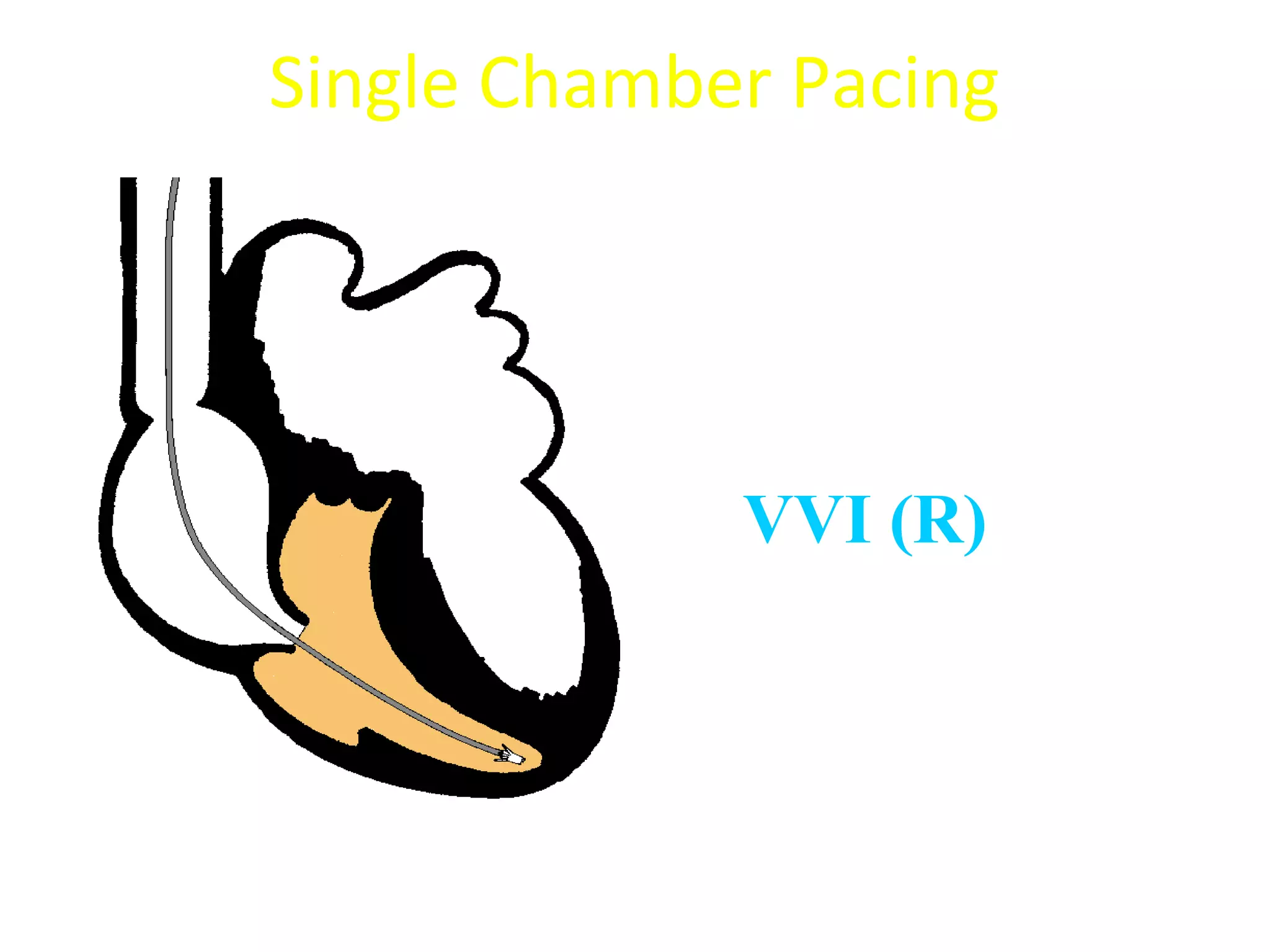
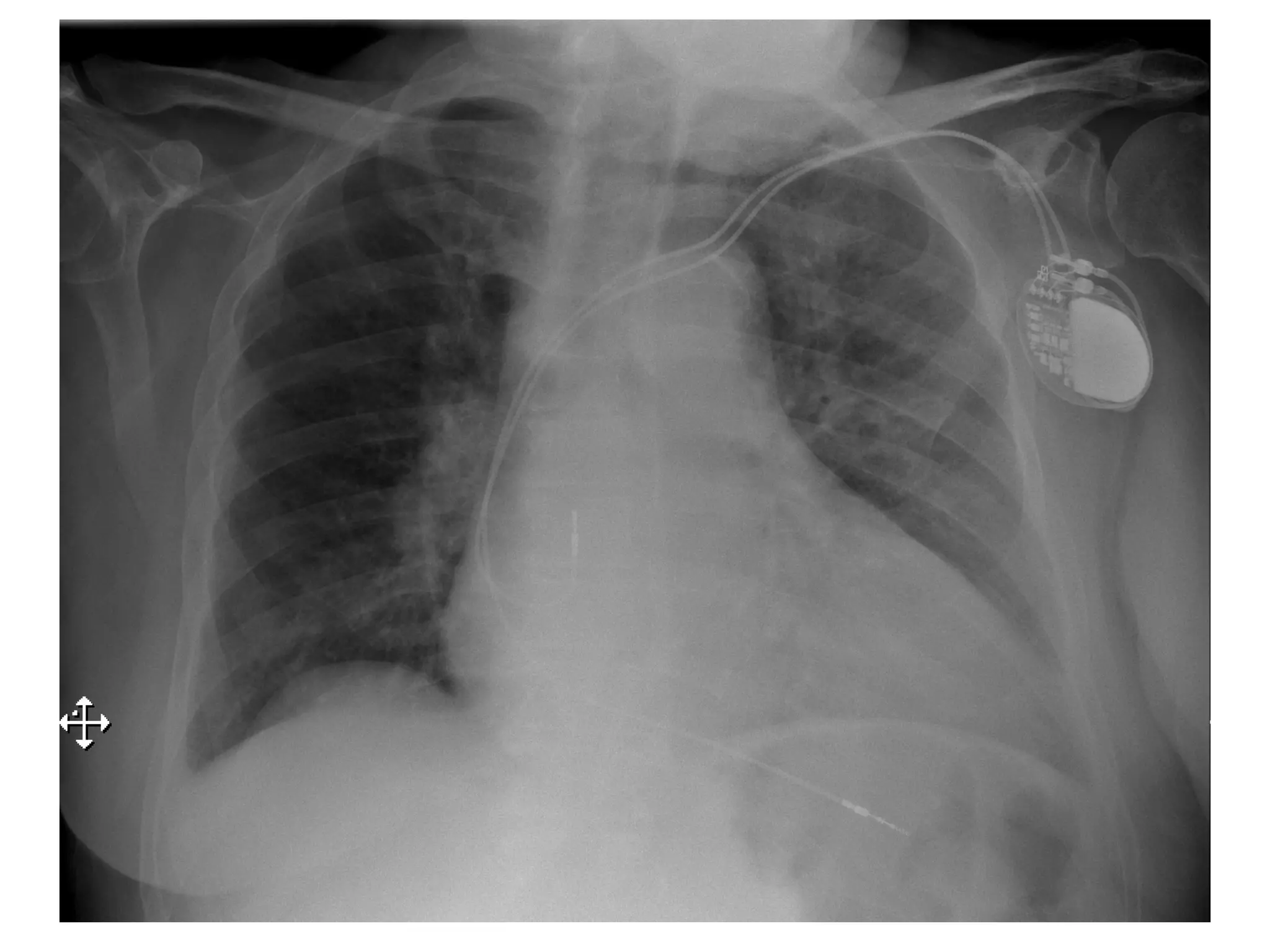
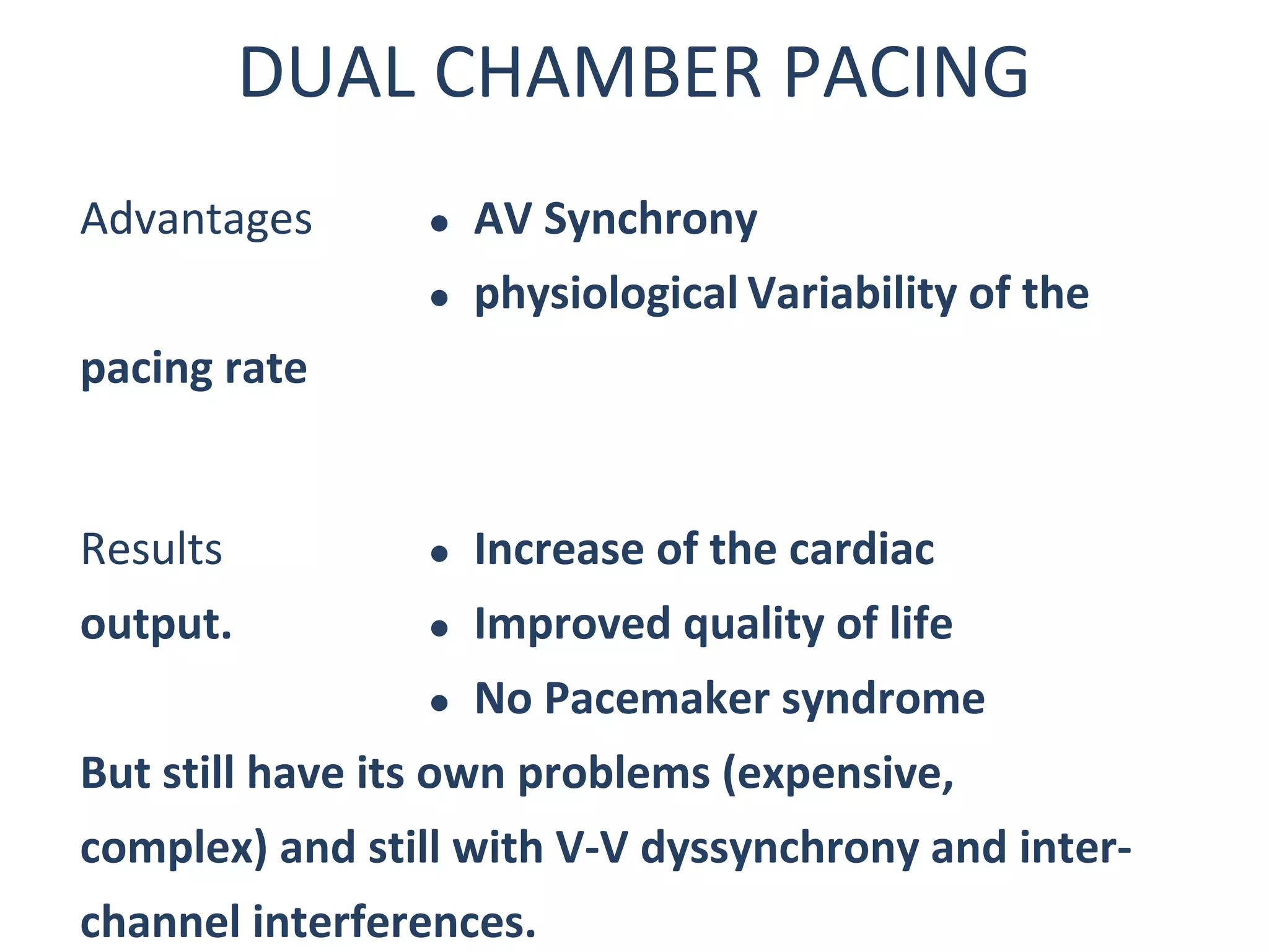
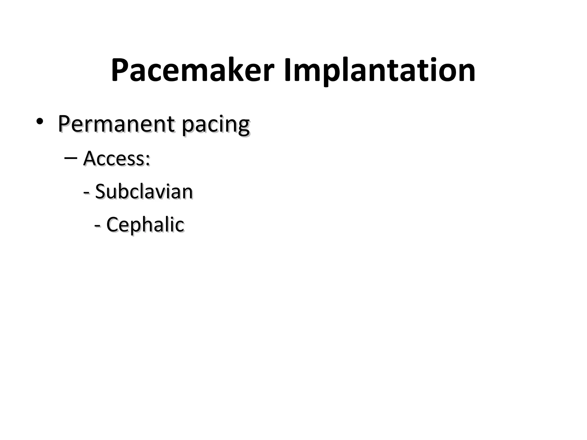
- The components, functions, and types of pacemakers including single vs dual chamber and permanent vs temporary pacing.
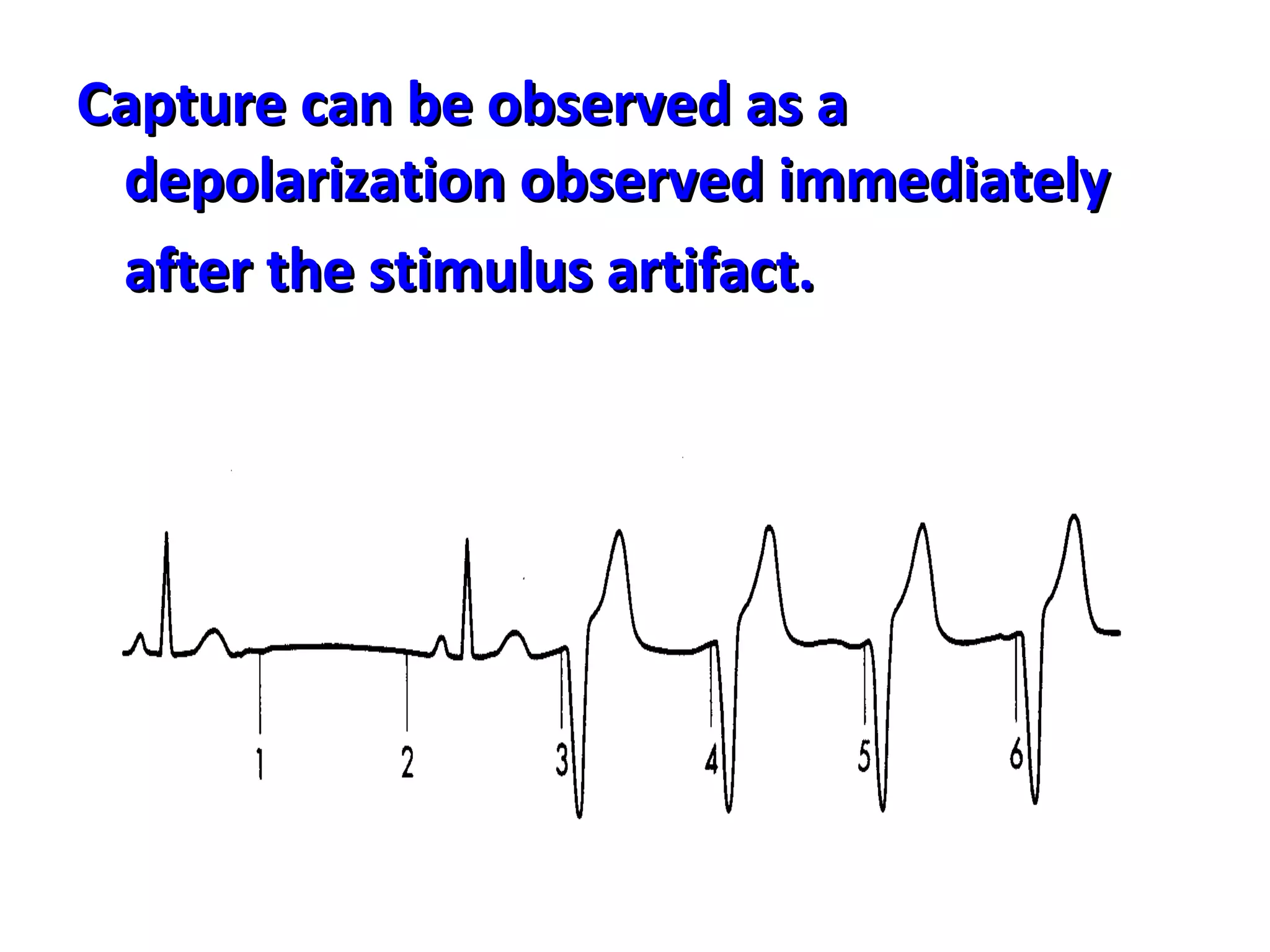
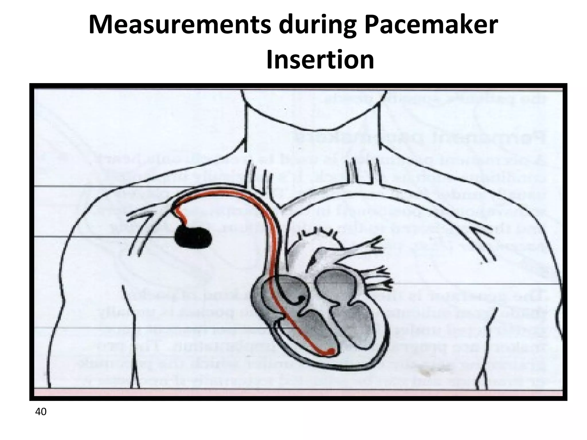
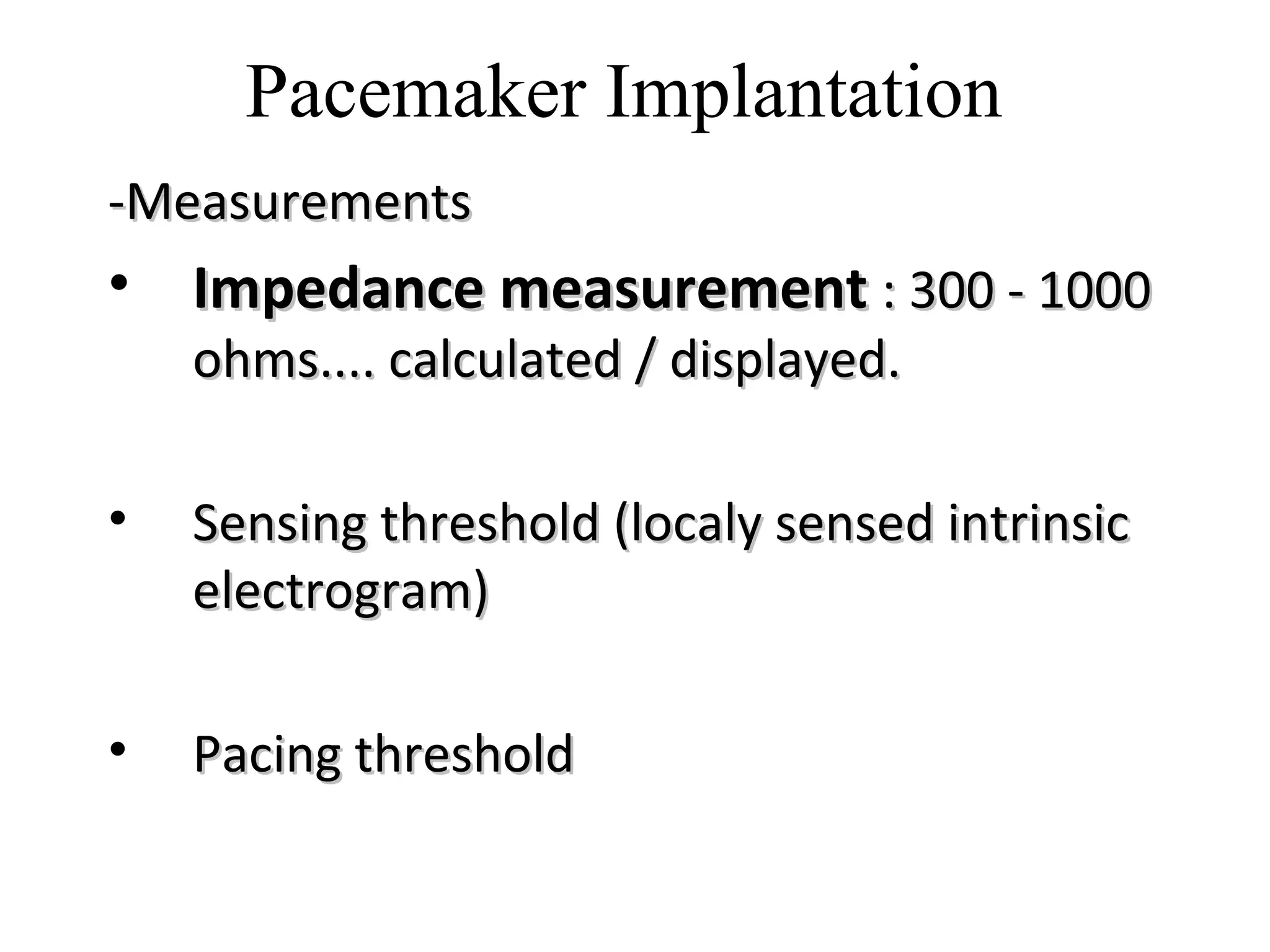
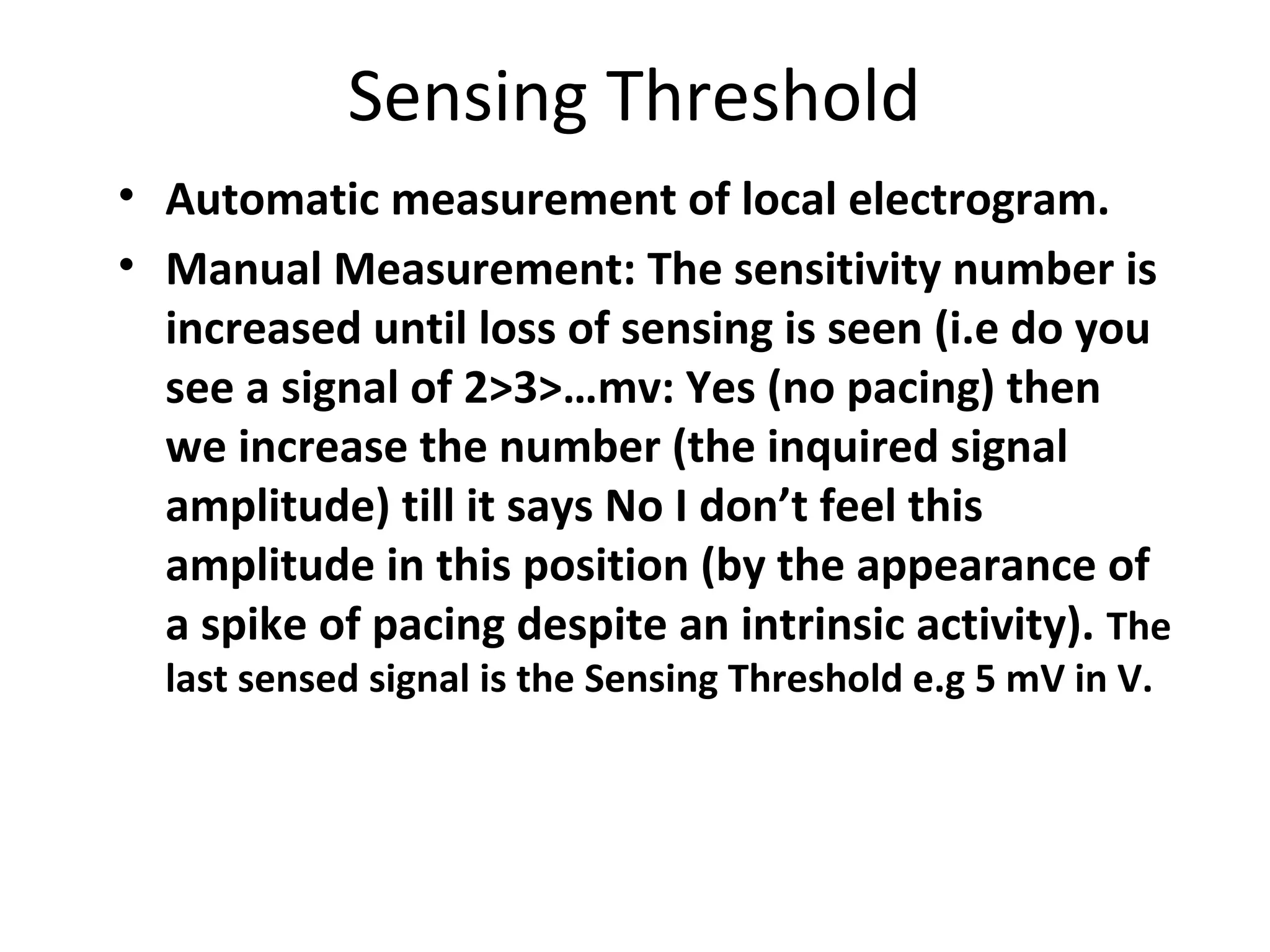
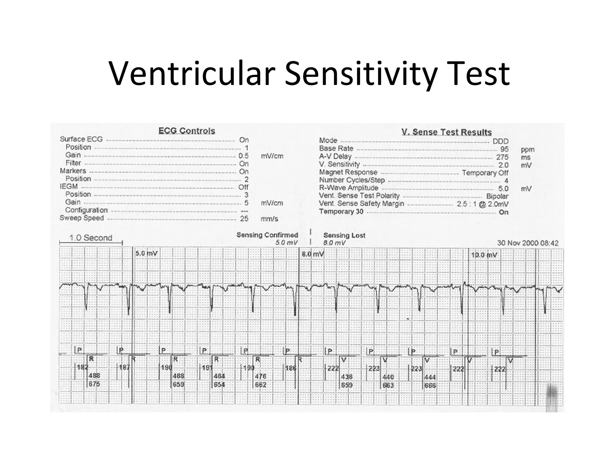
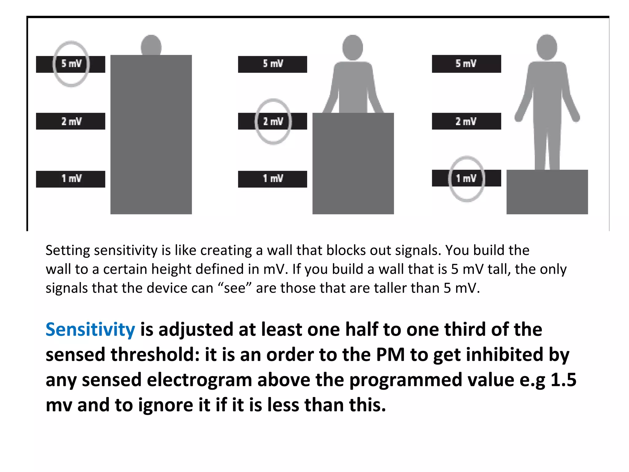
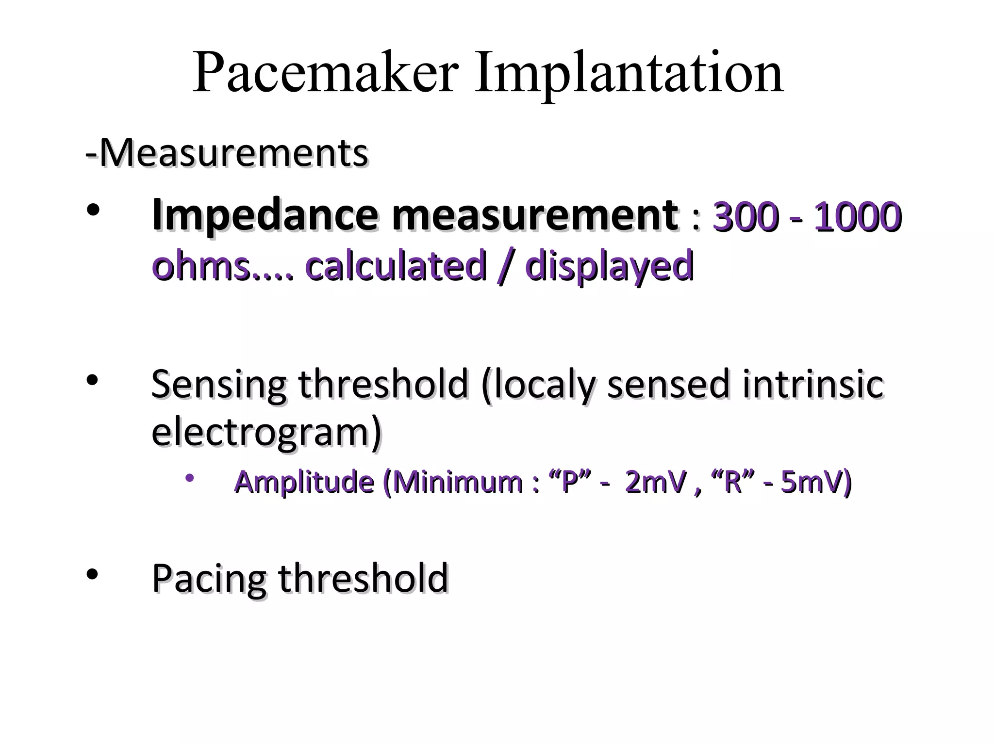
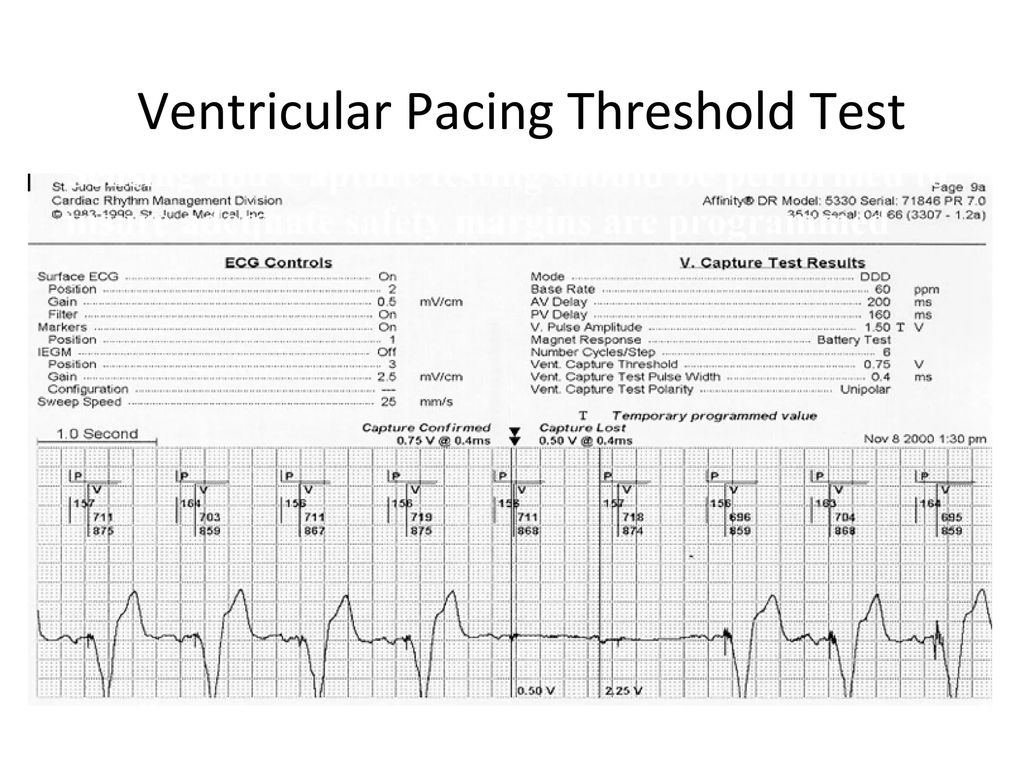
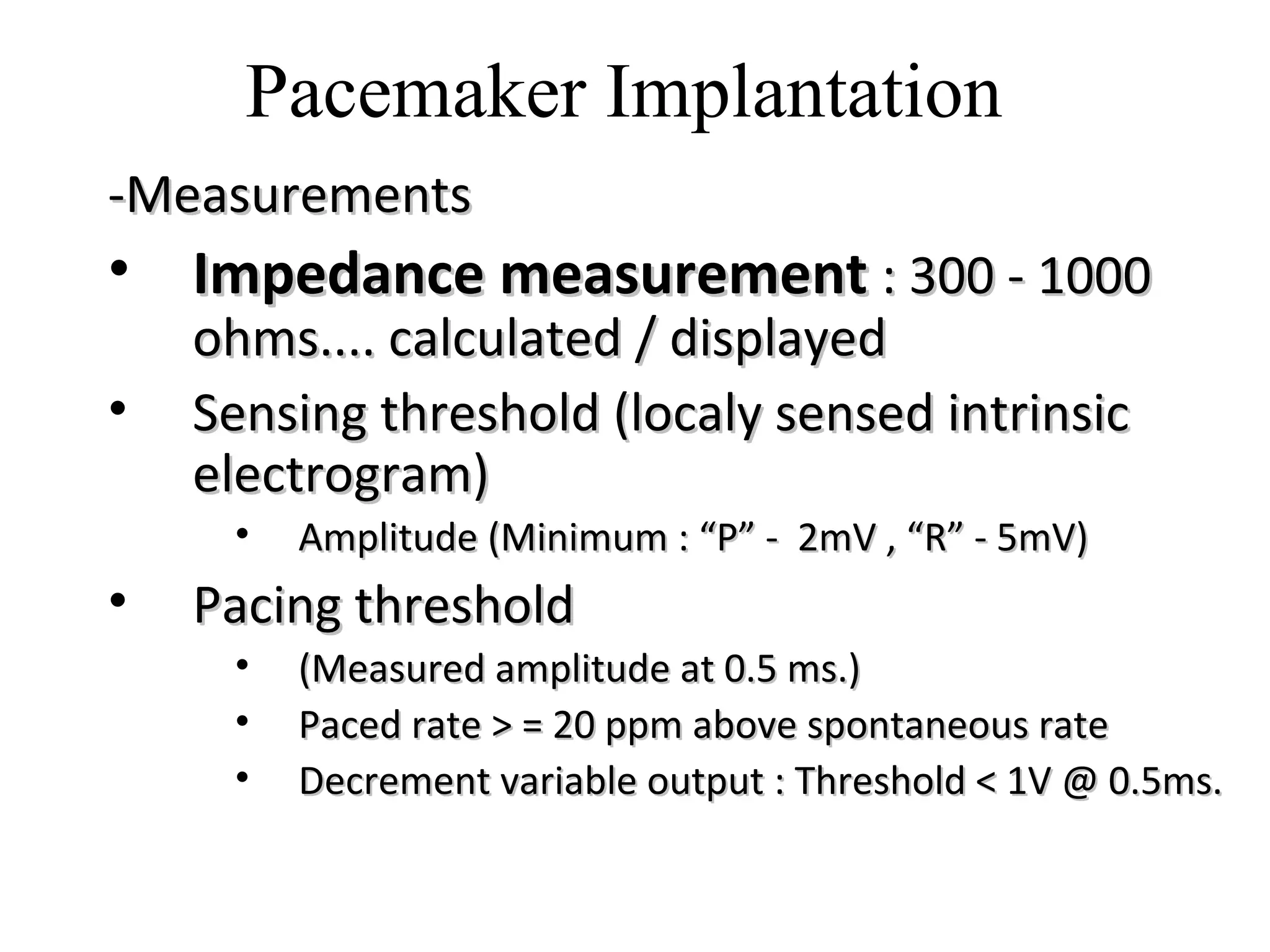
- Measurements taken during pacemaker implantation like impedance, sensing threshold, and pacing threshold to ensure proper function.
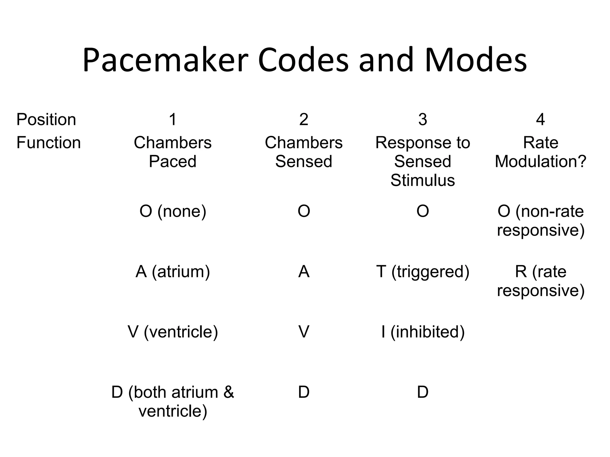
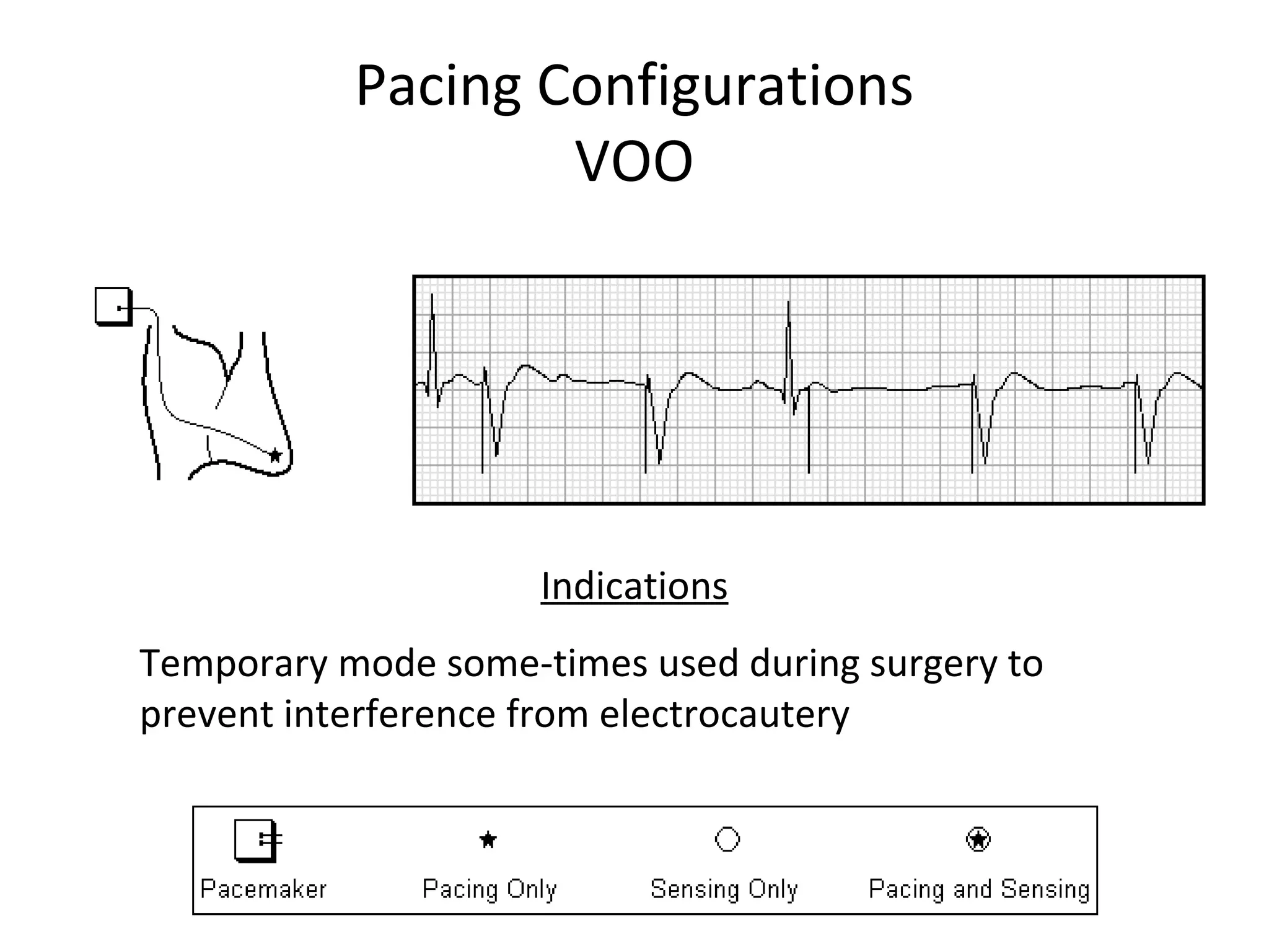
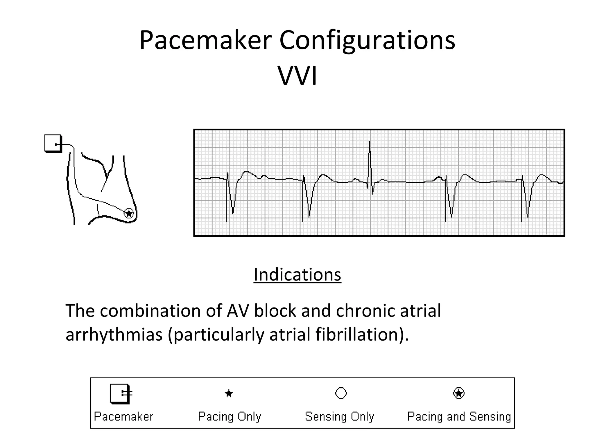
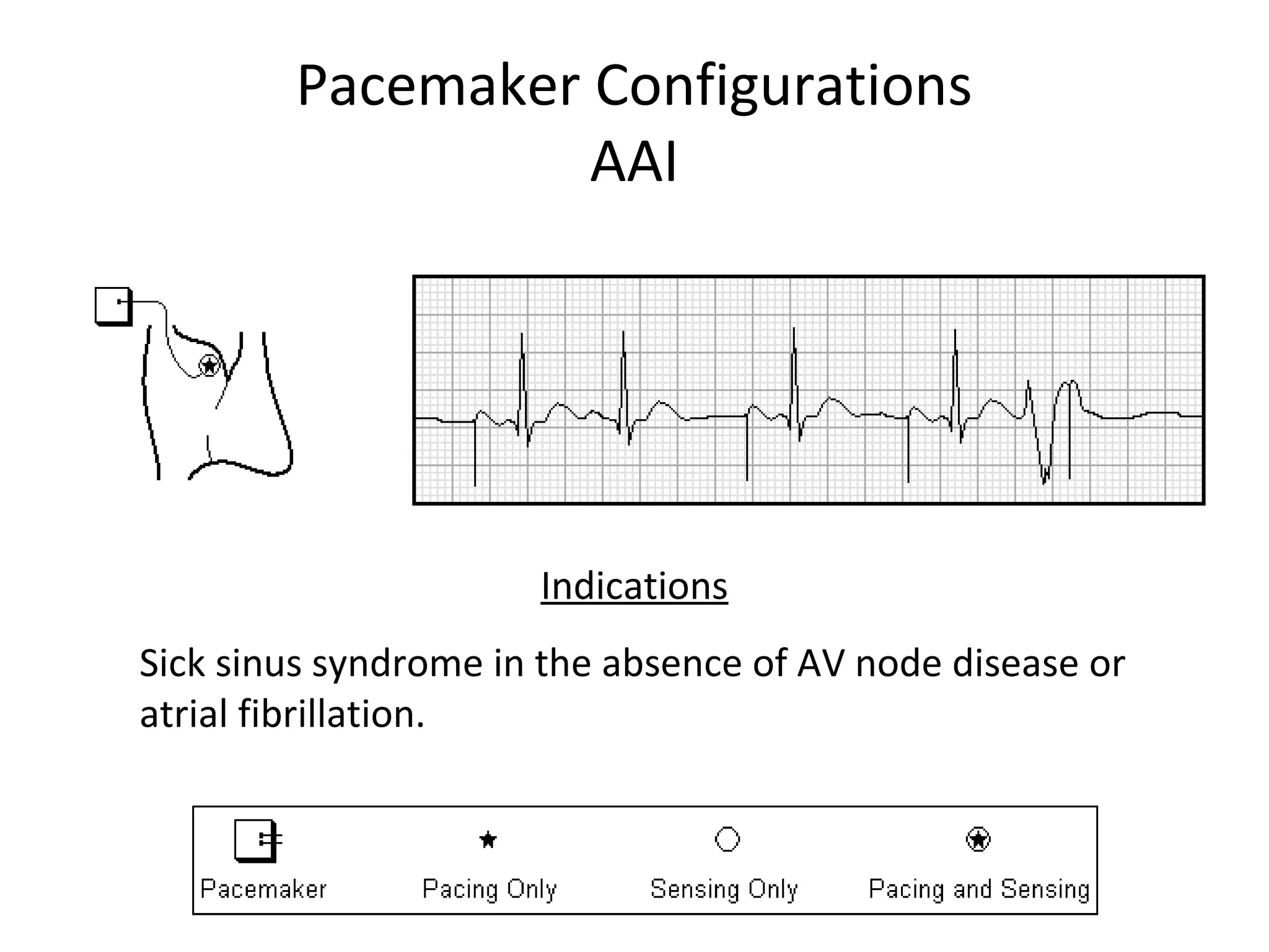
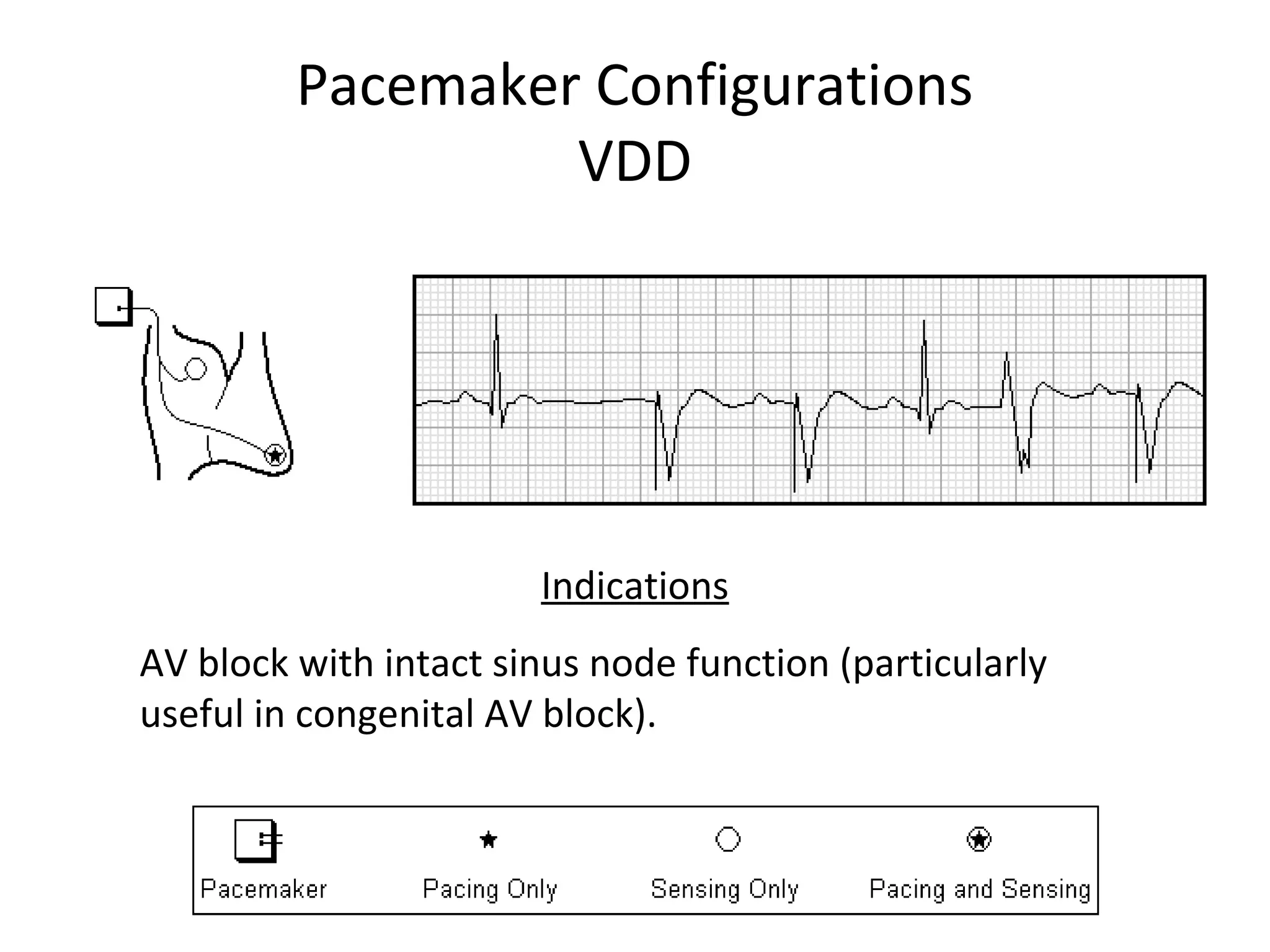
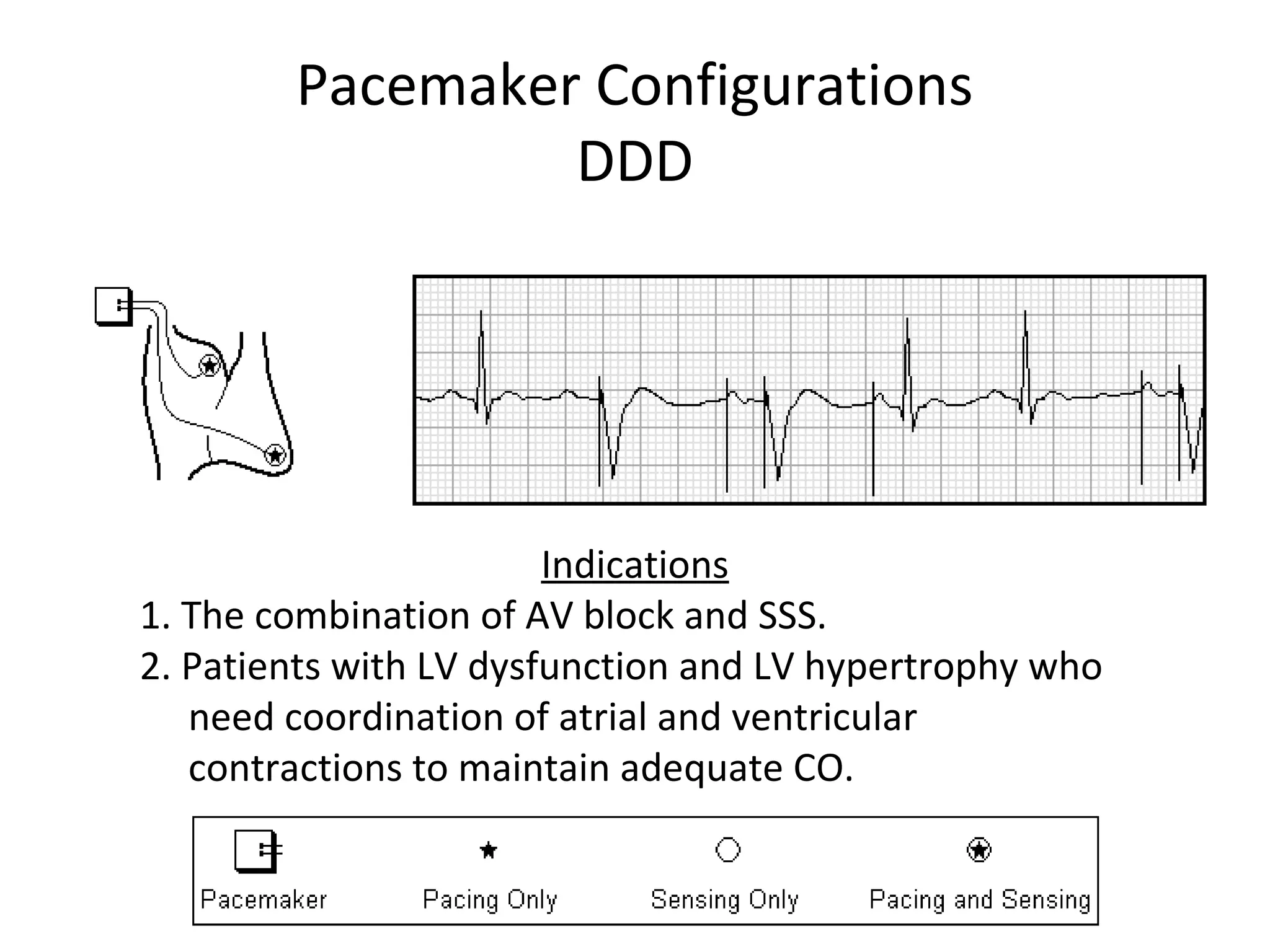
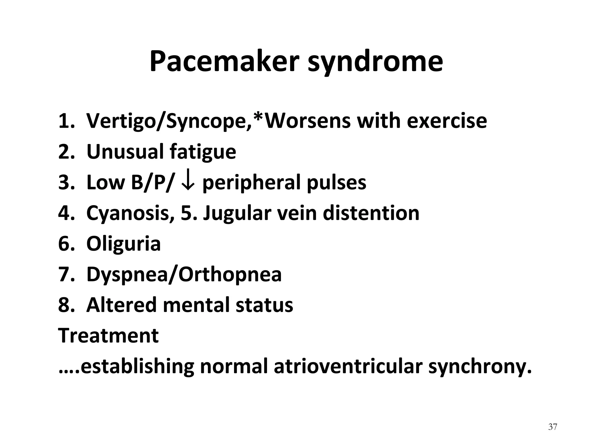
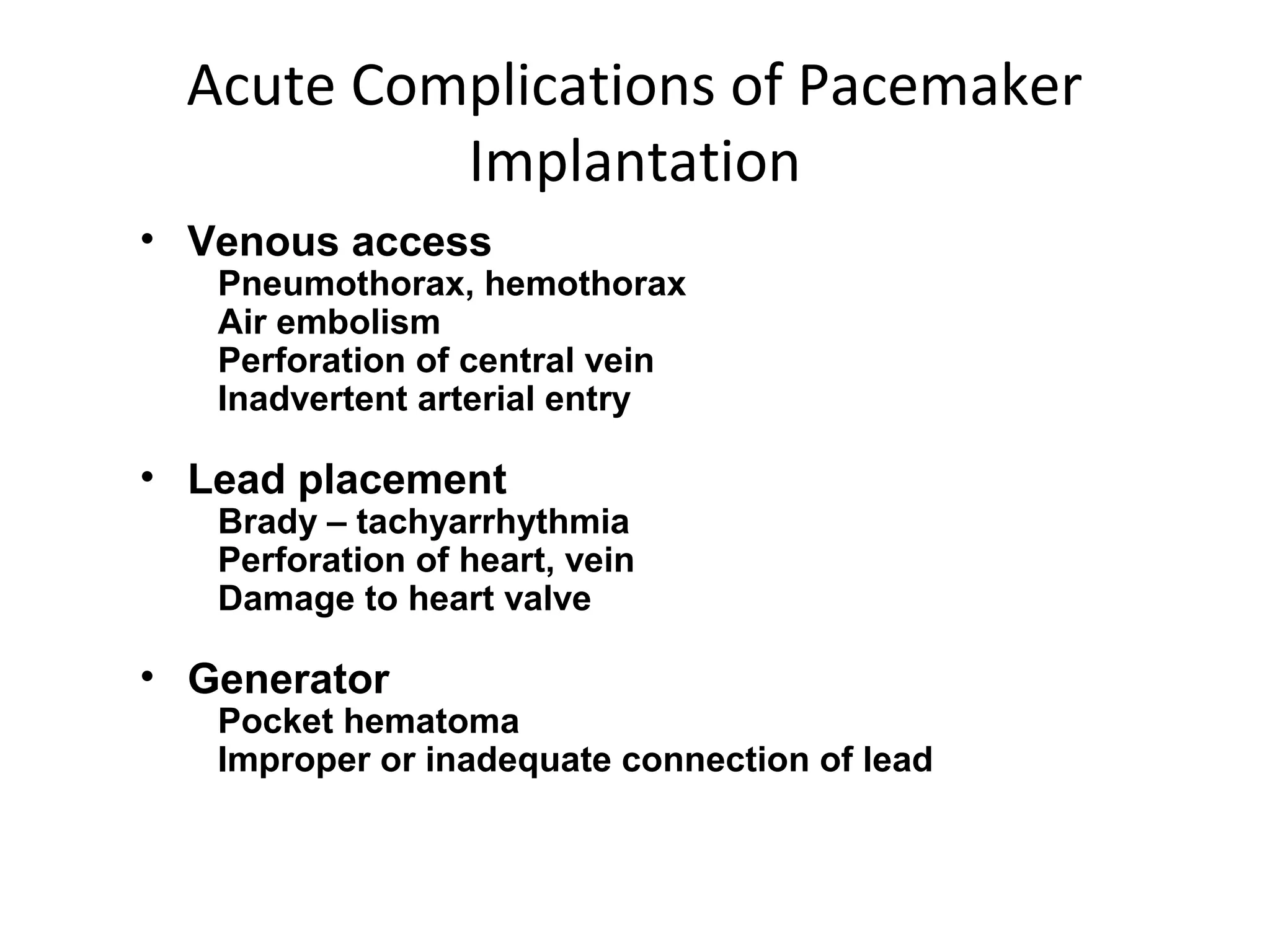
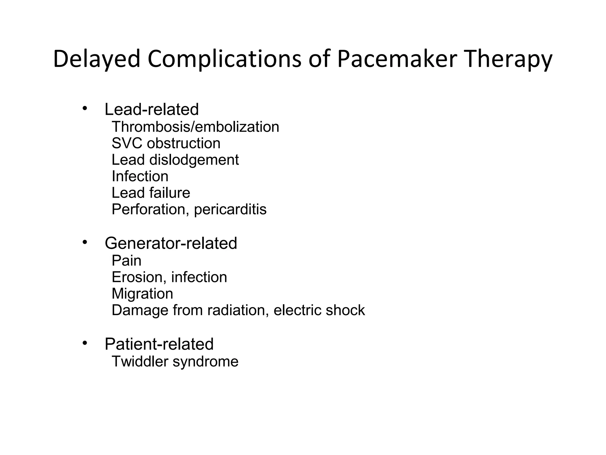
- Modes of pacing like VVI, DDD and indications for different modes. Potential complications of pacemaker therapy are also outlined.
The document serves as an introduction to pacemaker terminology, components, functions and the implantation process.