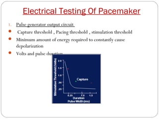
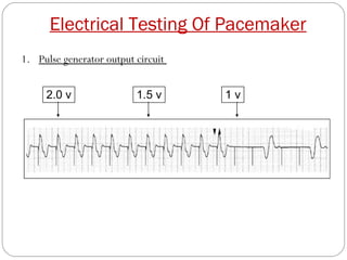
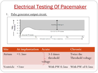
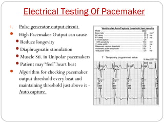
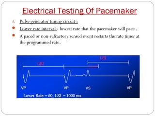
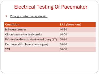
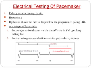
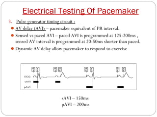
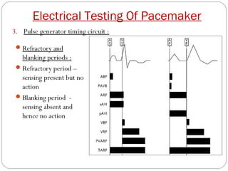
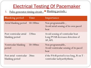
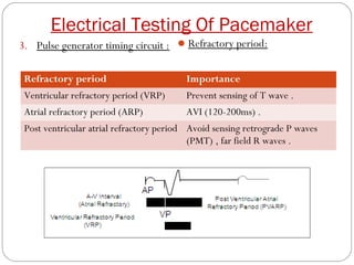
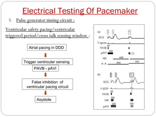
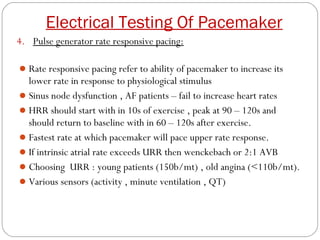
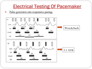
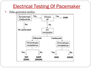
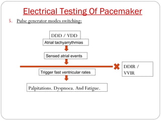
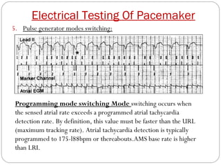
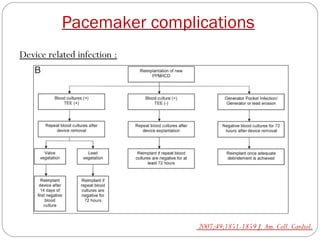
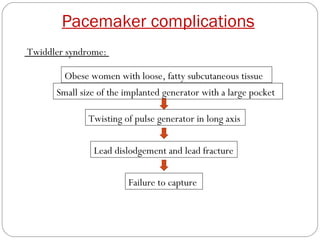
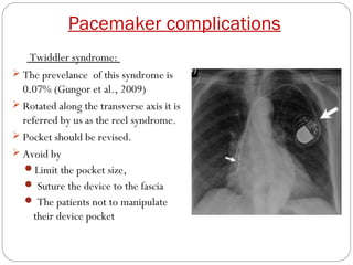
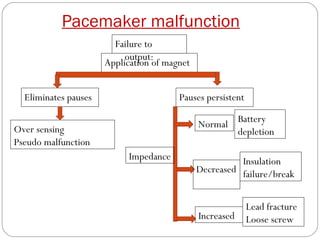
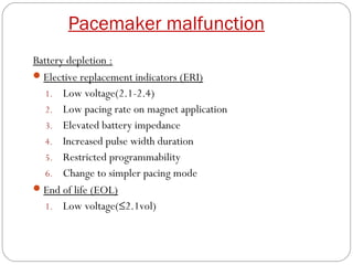
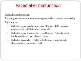
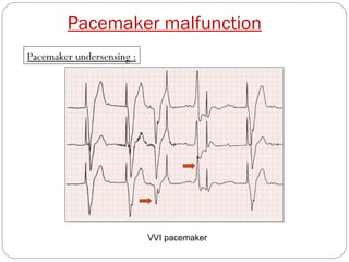
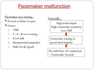
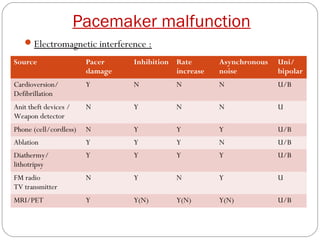
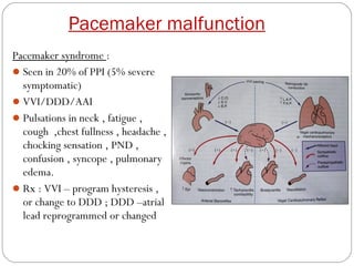
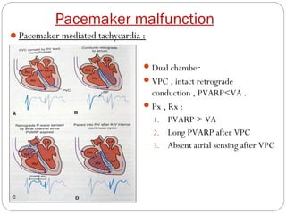
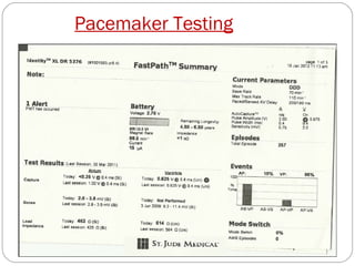
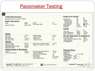
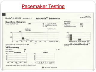
This document discusses electrical testing of pacemakers and pacemaker complications. It describes the components of a pacemaker including the battery, pacing impedance, pulse generator, and modes and mode switching. It then discusses testing various aspects of the pulse generator including output circuit, sensing circuit, timing circuit, and rate responsive pacing. Finally, it briefly outlines some common pacemaker complications such as pocket complications, lead issues, infections, and device malfunctions.
A patient with pacemaker presents a complex challenge to the attending anaesthesiologist. The mode of management will be according to the type of pacemaker implanted. This presentation discusses in brief the peri-operative consideration in a patient with pacemaker.
Wellens syndrome. Wellens syndrome (also referred to as LAD coronary T-wave syndrome) refers to an ECG pattern specific for critical stenosis of the proximal left anterior descending artery. The anomalies described occur in patients with recent anginal chest pain, and do not have chest pain when the ECG is recorded.
Congenital defects can put a strain on the heart, causing it to work harder. To stop your heart from getting weaker with this extra work, your doctor may try to treat you with medications. They are aimed at easing the burden on the heart muscle. You need to control your blood pressure if you have any type of heart problem.
Changing your lifestyle can help control and manage high blood pressure. Your health care provider may recommend that you make lifestyle changes including:
Eating a heart-healthy diet with less salt
Getting regular physical activity
Maintaining a healthy weight or losing weight
Limiting alcohol
Not smoking
Getting 7 to 9 hours of sleep daily
CRISPR technologies have progressed by leaps and bounds over the past decade, not only having a transformative effect on
biomedical research but also yielding new therapies that are poised to enter the clinic. In this review, I give an overview of (i)
the various CRISPR DNA-editing technologies, including standard nuclease gene editing, base editing, prime editing, and epigenome editing, (ii) their impact on cardiovascular basic science research, including animal models, human pluripotent stem
cell models, and functional screens, and (iii) emerging therapeutic applications for patients with cardiovascular diseases, focusing on the examples of Hypercholesterolemia, transthyretin amyloidosis, and Duchenne muscular dystrophy.
A post-splenectomy patient suffers from frequent infections due to capsulated bacteria like Streptococcus
pneumoniae, Hemophilus influenzae, and Neisseria meningitidis despite vaccination because of a lack of
memory B lymphocytes. Pacemaker implantation after splenectomy is less common. Our patient underwent
splenectomy for splenic rupture after a road traffic accident. He developed a complete heart block after
seven years, during which a dual-chamber pacemaker was implanted. However, he was operated on seven
times to treat the complication related to that pacemaker over a period of one year because of various
reasons, which have been shared in this case report. The clinical translation of this interesting observation
is that, though the pacemaker implantation procedure is a well-established procedure, the procedural
outcome is influenced by patient factors like the absence of a spleen, procedural factors like septic measures,
and device factors like the reuse of an already-used pacemaker or leads.
Transcatheter closure of patent ductus arteriosus (PDA) is feasible in low-birth-weight infants. A female baby was born prematurely with a birth weight of 924 g. She had a PDA measuring 3.7 mm. She was dependent on positive pressure ventilation for congestive heart failure in addition to the heart failure medications. She could not be discharged from the hospital even after 79 days of birth, and even though her weight reached 1.9 kg in the neonatal intensive care unit. We attempted to plug the PDA using an Amplatzer Piccolo Occluder, but the device failed to anchor. Then, the PDA was plugged using a 4-6 Amplatzer Duct Occluder using a 6-Fr sheath which was challenging.
Accidental misplacement of the limb lead electrodes is a common cause of ECG abnormality and may simulate pathology such as ectopic atrial rhythm, chamber enlargement or myocardial ischaemia and infarction
A Case of Device Closure of an Eccentric Atrial Septal Defect Using a Large D...Ramachandra Barik
Device closure of an eccentric atrial septal defect can be challenging and needs technical modifications to avoid unnecessary complications. Here, we present a case of a 45-year-old woman who underwent device closure of an eccentric defect with a large device. The patient developed pericardial effusion and left-sided pleural effusion due to injury to the junction of right atrium and superior vena cava because of the malalignment of the delivery sheath and left atrial disc before the device was pulled across the eccentric defect despite releasing the left atrial disc in the left atrium in place of the left pulmonary vein. These two serious complications were managed conservatively with close monitoring of the case during and after the procedure.
Trio of Rheumatic Mitral Stenosis, Right Posterior Septal Accessory Pathway a...Ramachandra Barik
A 57-year-old male presented with recurrent palpitations. He was diagnosed with rheumatic mitral stenosis, right posterior septal accessory pathway and atrial flutter. An electrophysiological study after percutaneous balloon mitral valvotomy showed that the palpitations were due to atrial flutter with right bundle branch aberrancy. The right posterior septal pathway was a bystander because it had a higher refractory period than the atrioventricular node.
Percutaneous balloon dilatation, first described by
Andreas Gruentzig in 1979, was initially performed
without the use of guidewires.1 The prototype
balloon catheter was developed as a double lumen
catheter (one lumen for pressure monitoring or
distal perfusion, the other lumen for balloon inflation/deflation) with a short fixed and atraumatic
guidewire at the tip. Indeed, initially the technique
involved advancing a rather rigid balloon catheter
freely without much torque control into a coronary
artery. Bends, tortuosities, angulations, bifurcations,
and eccentric lesions could hardly, if at all, be negotiated, resulting in a rather frustrating low procedural success rate whenever the initial limited
indications (proximal, short, concentric, noncalcified) were negated.2 Luck was almost as
important as expertise, not only for the operator,
but also for the patient. It is to the merit of
Simpson who, in 1982, introduced the novelty of
advancing the balloon catheter over a removable
guidewire, which had first been advanced in the
target vessel.3 This major technical improvement
resulted overnight in a notable increase in the procedural success rate. Guidewires have since evolved
into very sophisticated devices.
Optical coherence tomography-guided algorithm for percutaneous coronary intervention. Vessel diameter should be assessed using the external elastic lamina (EEL)-EEL diameter at the reference segments, and rounded down to select interventional devices (balloons, stents). If the EEL cannot be identified, luminal measures are used and rounded up to 0.5 mm larger for selection of the devices. Optical coherence tomography (OCT)-guided optimisation strategies post stent implantation per EEL-based diameter measurement and per lumen-based diameter measurement are shown. For instance, if the distal EEL-EEL diameter measures 3.2 mm×3.1 mm (i.e., the mean EEL-based diameter is 3.15 mm), this number is rounded down to the next available stent size and post-dilation balloon to be used at the distal segment. Thus, a 3.0 mm stent and non-compliant balloon diameter is selected. If the proximal EEL cannot be visualised, the mean lumen diameter should be used for device sizing. For instance, if the mean proximal lumen diameter measures 3.4 mm, this number is rounded up to the next available balloon diameter (within up to 0.5 mm larger) for post-dilation. MLA: minimal lumen area; MSA: minimal stent area;NC: non-compliant
Brugada syndrome (BrS) is an inherited cardiac disorder,
characterised by a typical ECG pattern and an increased
risk of arrhythmias and sudden cardiac death (SCD).
BrS is a challenging entity, in regard to diagnosis as
well as arrhythmia risk prediction and management.
Nowadays, asymptomatic patients represent the majority
of newly diagnosed patients with BrS, and its incidence
is expected to rise due to (genetic) family screening.
Progress in our understanding of the genetic and
molecular pathophysiology is limited by the absence
of a true gold standard, with consensus on its clinical
definition changing over time. Nevertheless, novel
insights continue to arise from detailed and in-depth
studies, including the complex genetic and molecular
basis. This includes the increasingly recognised
relevance of an underlying structural substrate. Risk
stratification in patients with BrS remains challenging,
particularly in those who are asymptomatic, but recent
studies have demonstrated the potential usefulness
of risk scores to identify patients at high risk of
arrhythmia and SCD. Development and validation of
a model that incorporates clinical and genetic factors,
comorbidities, age and gender, and environmental
aspects may facilitate improved prediction of disease
expressivity and arrhythmia/SCD risk, and potentially
guide patient management and therapy. This review
provides an update of the diagnosis, pathophysiology
and management of BrS, and discusses its future
perspectives.
The Human Developmental Cell Atlas (HDCA) initiative, which is part of the Human Cell Atlas, aims to create a comprehensive reference map of cells during development. This will be critical to understanding normal organogenesis, the effect of mutations, environmental factors and infectious agents on human development, congenital and childhood disorders, and the cellular basis of ageing, cancer and regenerative medicine. Here we outline the HDCA initiative and the challenges of mapping and modelling human development using state-of-the-art technologies to create a reference atlas across gestation. Similar to the Human Genome Project, the HDCA will integrate the output from a growing community of scientists who are mapping human development into a unified atlas. We describe the early milestones that have been achieved and the use of human stem-cell-derived cultures, organoids and animal models to inform the HDCA, especially for prenatal tissues that are hard to acquire. Finally, we provide a roadmap towards a complete atlas of human development.
The treatment of patients with advanced acute heart failure is still challenging.
Intra-aortic balloon pump (IABP) has widely been used in the management of
patients with cardiogenic shock. However, according to international guidelines, its
routinary use in patients with cardiogenic shock is not recommended. This recommendation is derived from the results of the IABP-SHOCK II trial, which demonstrated
that IABP does not reduce all-cause mortality in patients with acute myocardial infarction and cardiogenic shock. The present position paper, released by the Italian
Association of Hospital Cardiologists, reviews the available data derived from clinical
studies. It also provides practical recommendations for the optimal use of IABP in
the treatment of cardiogenic shock and advanced acute heart failure.
Left ventricular false tendons (LVFTs) are fibromuscular
structures, connecting the left ventricular
free wall or papillary muscle and the ventricular
septum.
There is some discussion about safety issues during
intense exercise in athletes with LVFTs, as these
bands have been associated with ventricular arrhythmias
and abnormal cardiac remodelling. However,
presence of LVFTs appears to be much more common
than previously noted as imaging techniques
have improved and the association between LVFTs
and abnormal remodelling could very well be explained
by better visibility in a dilated left ventricular
lumen.
Although LVFTsmay result in electrocardiographic abnormalities
and could form a substrate for ventricular
arrhythmias, it should be considered as a normal
anatomic variant. Persons with LVFTs do not appear
to have increased risk for ventricular arrhythmias or
sudden cardiac death.
4. Electrical Testing Of Pacemaker
Battery :
Lithium iodine battery
High energy density ,
Long shelf life ,
Predictable loss of battery
BOL (vol) – 2.8v
BOL (res) - <1komhs
5. Electrical Testing Of Pacemaker
Pacing impedance :
Pacing impedance refers to the opposition to current flow. Three
sources contribute to pacing impedance:
1. Pacing lead conductor coil
2. Electrode-tissue interface
Electrode resistance
Polarization
Normal lead impedance vary from 250-1200ohms.
Single impedance value may be of little use with out previous values
for comparison.
6. Electrical Testing Of Pacemaker
1.Pulse generator output circuit
Capture threshold , Pacing threshold , stimulation threshold
Minimum amount of energy required to constantly cause
depolarization
Volts and pulse duration
8. Electrical Testing Of Pacemaker
1. Pulse generator output circuit
Site At implantation Acute Chronic
Atrium <1.5mv 3-5 times Twice the
threshold Threshold voltage
voltage
Ventricle <1mv With PW 0.5ms With PW of 0.5ms
9. Electrical Testing Of Pacemaker
1.Pulse generator output circuit
High Pacemaker Output can cause
Reduce longevity
Diaphragmatic stimulation
Muscle Sti. in Unipolar pacemakers
Patient may “feel” heart beat
Algorithm for checking pacemaker
output threshold every beat and
maintaining threshold just above it -
Auto capture.
10. Electrical Testing Of Pacemaker
2.Pulse generator sensing circuit :
Ability of the device to detect intrinsic beat of the heart
Measured - peak to peak magnitude (mv) & slew rate(mv/ms)
11. Electrical Testing Of Pacemaker
2. Pulse generator sensing circuit :
Reduce Lower Rate below intrinsic rate to inhibit pacing and ensure
intrinsic activity
Increase sensitivity setting while observing EGM. The sensitivity
value at which sensing is lost on the EGM is the sensing threshold.
Sensitivity threshold safety is twice the attained valve.
Sensitivity Slew rate
Atrium 1-2mv(0.5mv) > 0.5 v/s
ventricle 2-3mv > 0.75 v/s
12. Electrical Testing Of Pacemaker
3. Pulse generator timing circuit :
a. Lower rate limit (LRL)
b. Hysteresis rate
c. Refractory and blanking periods
d. Ventricular safety pacing interval .
e. Upper rate response .
13. Electrical Testing Of Pacemaker
3.Pulse generator timing circuit :
Lower rate interval - lowest rate that the pacemaker will pace .
A paced or non-refractory sensed event restarts the rate timer at
the programmed rate.
15. Electrical Testing Of Pacemaker
3. Pulse generator timing circuit :
Hysteresis :
Hysteresis allows the rate to drop below the programmed pacing LRL.
Advantages of hysteresis :
1. Encourages native rhythm – maintain AV sync in VVI , prolong
battery life
2. Prevent retrograde conduction – avoids pacemaker syndrome
16. Electrical Testing Of Pacemaker
3. Pulse generator timing circuit :
AV delay (AVI) – pacemaker equivalent of PR interval.
Sensed vs paced AVI – paced AVI is programmed at 125-200ms ,
sensed AV interval is programmed at 20-50ms shorter than paced.
Dynamic AV delay allow pacemaker to respond to exercise
sAVI – 150ms
pAVI – 200ms
17. Electrical Testing Of Pacemaker
3. Pulse generator timing circuit :
AV delay (AVI)
Longer AVI :
Good AV conduction – maintains AV synchrony , long battery life
Achieved by following methods :Programming longer AVI ,
managed ventricular pacing , AV delay hysteresis .
Shorter AVI:
HOCM – RV apical pacing decreases HOCM gradient
CRT – usually 80-120ms , for 100%ventricular pacing and optimize CO
Physiological response to faster heart rates can be answered
18. Electrical Testing Of Pacemaker
3. Pulse generator timing circuit :
Refractory and
blanking periods :
Refractory period –
sensing present but no
action
Blanking period -
sensing absent and
hence no action
19. Electrical Testing Of Pacemaker
3. Pulse generator timing circuit : Blanking periods :
Blanking period Time Importance
Atrial blanking period 50-100ms Non programmable ,
Avoid atrial sensing of its own paced
beat
Post ventricular atrial 220ms Avoid sensing of ventricular beat
blanking period Long PVAB decreases detection of
AF,AFL
Ventricular blanking 50-100ms Non programmable,
period Avoid ventricular sensing of its paced
beat
Post atrial ventricular 28ms if the PAvB period is too long, R on T -
blanking period ventricular tachyarrhythmia.
20. Electrical Testing Of Pacemaker
3. Pulse generator timing circuit : Refractory period:
Refractory period Importance
Ventricular refractory period (VRP) Prevent sensing of T wave .
Atrial refractory period (ARP) AVI (120-200ms) .
Post ventricular atrial refractory period Avoid sensing retrograde P waves
(PMT) , far field R waves .
22. Electrical Testing Of Pacemaker
4. Pulse generator rate responsive pacing:
Rate responsive pacing refer to ability of pacemaker to increase its
lower rate in response to physiological stimulus
Sinus node dysfunction , AF patients – fail to increase heart rates
HRR should start with in 10s of exercise , peak at 90 – 120s and
should return to baseline with in 60 – 120s after exercise.
Fastest rate at which pacemaker will pace upper rate response.
If intrinsic atrial rate exceeds URR then wenckebach or 2:1 AVB
Choosing URR : young patients (150b/mt) , old angina (<110b/mt).
Various sensors (activity , minute ventilation , QT)
25. Electrical Testing Of Pacemaker
5. Pulse generator modes switching:
DDD / VDD
Atrial tachyarrythmias
Sensed atrial events
DDIR /
Trigger fast ventricular rates VVIR
Palpitations. Dyspnoea. And Fatigue.
26. Electrical Testing Of Pacemaker
5. Pulse generator modes switching:
Programming mode switching Mode switching occurs when
the sensed atrial rate exceeds a programmed atrial tachycardia
detection rate. By definition, this value must be faster than the URL
(maximum tracking rate). Atrial tachycardia detection is typically
programmed to 175-l88bpm or thereabouts.AMS base rate is higher
than LRI.
27. Electrical Testing Of Pacemaker
Pacemaker follow up guidelines: Transtelephonic monitoring guidelines
Medicare guidelines
Single chambered pacing Dual chambered pacing
1st month q 2 week 1st month q 2 weeks
2nd -48th month q 12 week 2nd – 30th month q 12weeks
49th – 72nd month q 8 week 31st – 48th month q 8 weeks
73rd month and later q 4 weeks 49th month and later q 4week
NASPE guidelines
Single or dual pacing
1st visit 6 – 8 week post implant , if symptomatic prior to this
5th month
From 6th month q 3month
Battery wear present q 1month
30. Pacemaker complications
Pocket hematoma :
The risk of haematoma is increased in patients taking antithrombotic
or anticoagulant drugs (Goldstein et al., 1998).
Most small hematomas can be managed conservatively with cold
compress and withdrawal of antiplatelet or antithrombotic agents.
Occasionally, large hematomas that compromise the suture line or
skin integrity may have to be surgically evacuated.
Needle aspiration increases risk of infection and should not be done.
31. Pacemaker complications
Pocket hematoma :
In patients requiring oral anticoagulants (warfarin), to take INR of
about 2.0 at the time of implantation is safe (Belott & Reynolds, 2000).
Unfractionated heparin or low-molecular-weight heparin are always
discontinued prior to device implant and ideally avoided for a
minimum of 24 hours post implantation.
Administration of anticoagulants can be resumed within 48-72 h after
implantation if there is no evidence of substantial hematoma formation.
32. Pacemaker complications
Device-related infections :
The reported incidence of pacemaker-related infection ranges from
0.5% to 6% in early series
The use of prophylactic antibiotics and pocket irrigation with antibiotic
solutions has decreased the rate of acute infections following pacemaker
implantations to <1 to 2 percent in most series
The mortality of persistent infection when infected leads are not
removed can be as high as 66%.
DM, malignancy, operator inexperience, advanced age, corticosteroid
use, anticoagulation, recent device manipulation, CRF, and bacteremia
from a distant focus of infection.
33. Pacemaker complications
Device related infection :
Device infection is defined as either:
(a) deep infection - infection involving the generator pocket
and/or the intravenous portion of the leads, with bacteremia,
requiring device extraction or
(b) superficial infection - characterized by local inflammation,
involving the skin but not the generator pocket, and treated with
oral antibiotics.
37. Pacemaker complications
Wound pain :
Infection , Pacemaker implanted too superficially , Pacemaker
implanted too laterally , Pacemaker allergy .
Skin erosion :
Incidence has been estimated around 0.8% .Old age , infection.
Surgical revision of pocket and reimplantation .
Allergic reactions :
Always rule out infection before coming to diagnosis of allergy
38. Pacemaker complications
Lead dislodgement:
Relatively common – 5-10% of
patients(ICD database 2001)
Atrial more common than
ventricular(2-3% vs. 1%)
Micro dislodgement , macro
dislodgement
Increased pacing threshold , failure
to pace and sense
Active fixation (decreases risk)
39. Pacemaker complications
Pneumothorax , :
Uncommon complication – 1.6-2.6%
During or 48 hrs after procedure
Inadvent puncture and laceration of
subclavian vein , artery or lung
Related to operator experience and
underlying anatomy
Avoided by
1. Venogram – flouroscpic puncture
2. Axillary venous access (Martin etal’96)
3. One way mechanism sheath
40. Pacemaker complications
Cardiac Perforation :
Uncommon but potentially serious complication - lower than 1%.
Acute (<5 days) , subacute(5d-1month) , chronic (>1month)
Increasing stimulation threshold , RBBB pattern for RV pacing,
intercostal muscle or diaphragmatic contraction, friction rub, and
pericarditis, pericardial effusion, or cardiac tamponade.
CXR , ECHO , CT
Lead withdrawal and repositioning ; surgical back up
42. Pacemaker complications
Extracardiac stimulation
The diaphragm or pectoral or intercostal muscles
Diaphragmatic stimulation - direct stimulation of the diaphragm (left)
or stimulation of the phrenic nerve (right).
Early postimplantation period , dislodgment of the pacing lead.
MC in patients with LV coronary vein branch lead placement for CRT
Output pacing importance (testing and treatment)
Pectoral stimulation - incorrect orientation of the pacemaker or a
current leak from a lead insulation failure or exposed connector.
43. Pacemaker complications
Venous thrombosis :
Venous thrombosis occurs in 30% to 50% of patients and only 1-3%
of patients become symptomatic.
Manifestations vary from usually asymptomatic, acute symptomatic
thrombosis, and even SVCS .
Early or late after pacemaker implantation.
Predictors of severe stenosis are multiple pacemaker leads , previous
pacing , double coils , hormone therapy .
Asymptomatic (no treatment) , symptomatic (anticoagulants –
endovascular stents – surgical correction ).
44. Pacemaker complications
Twiddler syndrome:
Obese women with loose, fatty subcutaneous tissue
Small size of the implanted generator with a large pocket
Twisting of pulse generator in long axis
Lead dislodgement and lead fracture
Failure to capture
45. Pacemaker complications
Twiddler syndrome:
The prevelance of this syndrome is
0.07% (Gungor et al., 2009)
Rotated along the transverse axis it is
referred by us as the reel syndrome.
Pocket should be revised.
Avoid by
Limit the pocket size,
Suture the device to the fascia
The patients not to manipulate
their device pocket
46. Pacemaker malfunction
Failure to capture
Failure to output
Sensing abnormalities(under and over sensing)
Specific mode complications
1. Pacemaker related tachycardia
2. Pacemaker syndrome
47. Pacemaker malfunction
Failure to capture:
Pacing artifact present but no evoked potential .
Causes
1. Lead dislodgement or perforation
2. Lead maturation(inflammation/fibrosis)(exit block)
3. Battery depletion
4. Circuit failure(coil fracture , insulation defect)
5. Capture management algorithm failure
6. Inappropriate programming
7. Pseudo malfunction
8. Functional non capture
9. Metabolic , drugs , cardiomyopathies
48. Pacemaker malfunction
Failure to capture:
Electrocardiographic tracing from a patient with a DDDR pacemaker. All ventricular
pacing artifacts but one failed to result in ventricular depolarization—
that is, failure to capture
49. Pacemaker malfunction
Failure to capture:
Pacing threshold
Normal Increased
Dislodgement
Normal Exit block
Battery depletion
Functional non capture
Impedance Insulation
Decreased failure/break
Lead fracture
Increased Loose screw
50. Pacemaker malfunction
Failure to output:
Absence of pacing stimuli and hence no capture .
Causes
1. Pseudo malfunction - hysteresis , PMT termination , sleep rate
2. Over sensing - EMI ; T P R over sensing ;
Myopotential/diaphragmatic ; Cross talk ; Make break signals
3. Open circuit - lead fracture , loose screw , air in the pocket ,
incompatible lead .
4. Battery depletion
5. Recording artifact.
51. Pacemaker malfunction
Failure to output:
VVIR pacemaker This patient had a pacemaker programmed to a unipolar
sensing configuration. The sensing of myopotentials led to symptomatic
pauses, and reprogramming the pacemaker to a bipolar sensing configuration
prevented subsequent myopotential over sensing.
52. Pacemaker malfunction
Failure to
output:
Application of magnet
Eliminates pauses Pauses persistent
Over sensing Normal Battery
depletion
Pseudo malfunction
Impedance Insulation
Decreased failure/break
Lead fracture
Increased Loose screw
53. Pacemaker malfunction
Battery depletion :
Elective replacement indicators (ERI)
1. Low voltage(2.1-2.4)
2. Low pacing rate on magnet application
3. Elevated battery impedance
4. Increased pulse width duration
5. Restricted programmability
6. Change to simpler pacing mode
End of life (EOL)
1. Low voltage(≤2.1vol)
54. Pacemaker malfunction
Pacemaker undersensing :
Pacing artifact present but no sensing(sensed beat doesn’t reset cycle)
Causes are
1. Defect in signal production – scar /fibrosis , BBB , ectopic ,
cardioversion , defibrillation , metabolic.
2. Defect in signal transmission – lead fracture /dislodgement ,
insulation failure , partial open circuit.
3. Defect in pacemaker – battery depletion , sensing circuit
abnormalities , committed DVI.
56. Pacemaker malfunction
Pacemaker over sensing :
Cross talk :
Present as failure to pace
High atrial output
Causes
High ventricular sensitivity
1. EMI Low VBP
2. T , P , R over sensing .
3. Cross talk Ventricular sensing of
4. Myopotential (unipolar) paced atrial impulse
5. Make break signals
Pts with Poor AV conduction
– Ventricular Asystole
57. Pacemaker malfunction
Electromagnetic interference :
Source Pacer Inhibition Rate Asynchronous Uni/
damage increase noise bipolar
Cardioversion/ Y N N N U/B
Defibrillation
Anit theft devices / N Y N N U
Weapon detector
Phone (cell/cordless) N Y Y Y U/B
Ablation Y Y Y N U/B
Diathermy/ Y Y Y Y U/B
lithotripsy
FM radio N Y N Y U
TV transmitter
MRI/PET Y Y(N) Y(N) Y(N) U/B
58. Pacemaker malfunction
Pacemaker syndrome :
Seen in 20% of PPI (5% severe
symptomatic)
VVI/DDD/AAI
Pulsations in neck , fatigue ,
cough ,chest fullness , headache ,
chocking sensation , PND ,
confusion , syncope , pulmonary
edema.
Rx : VVI – program hysteresis ,
or change to DDD ; DDD –atrial
lead reprogrammed or changed
59. Pacemaker malfunction
Pacemaker mediated tachycardia :
Dual chamber
VPC , intact retrograde
conduction , PVARP<VA .
Px , Rx :
1. PVARP > VA
2. Long PVARP after VPC
3. Absent atrial sensing after VPC