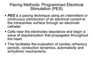
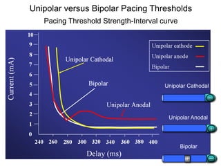
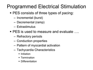
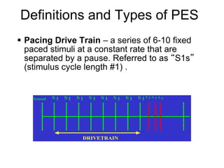
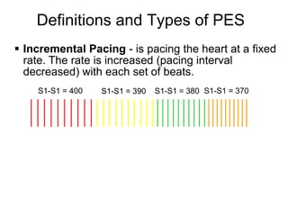
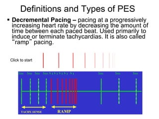
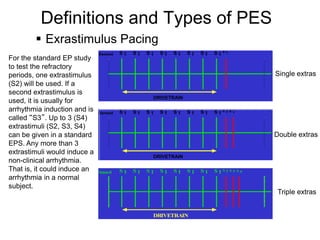
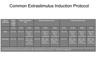
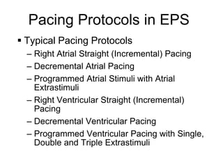
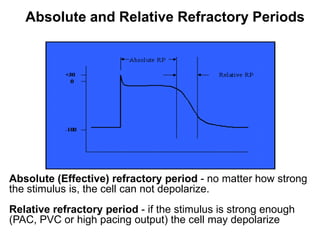
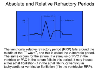
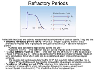
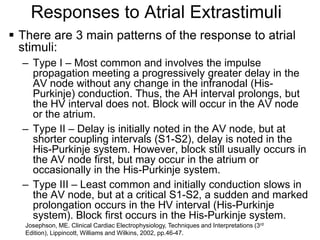
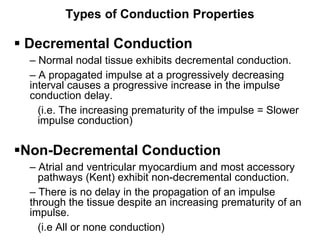
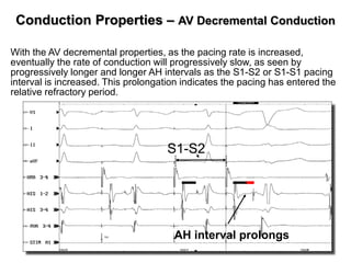
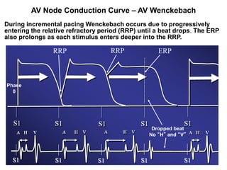
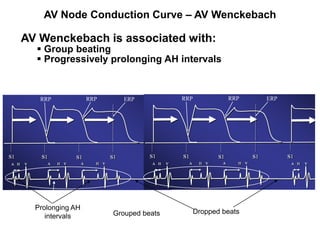
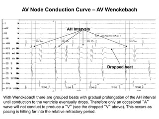
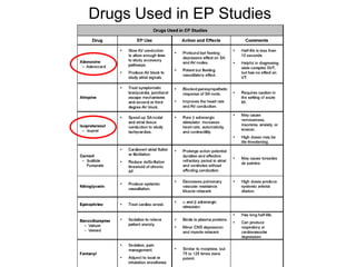
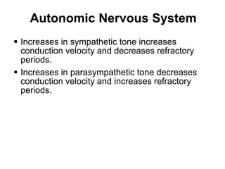
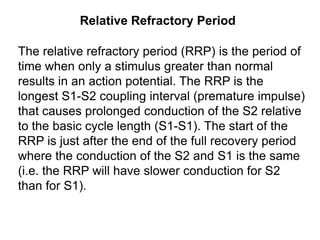
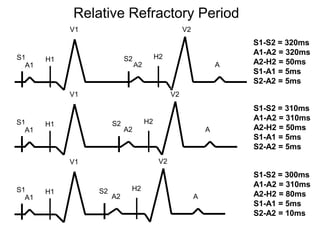
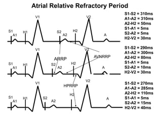
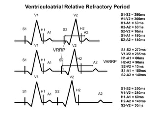
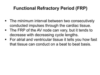
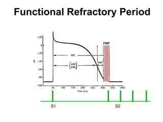
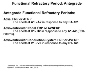
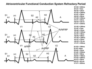
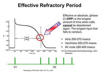
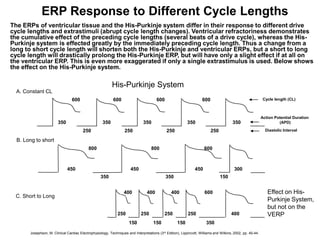
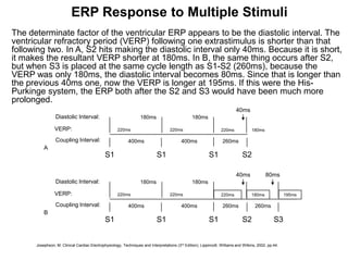
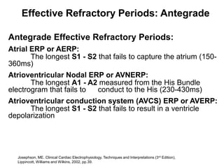
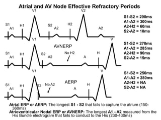
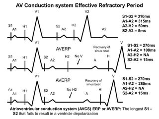
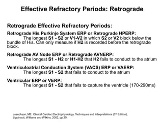
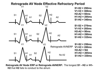
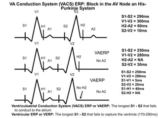
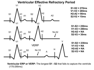
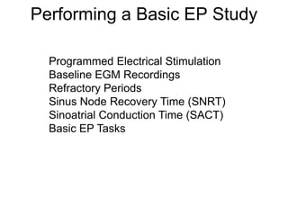
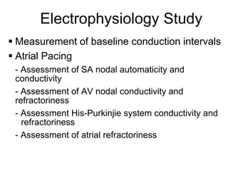
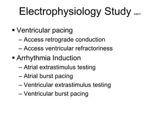
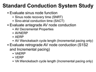
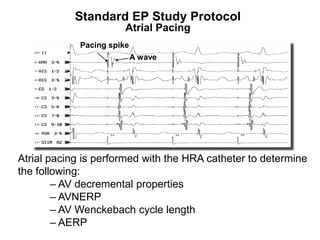
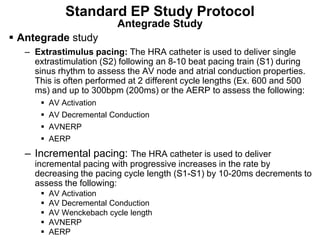
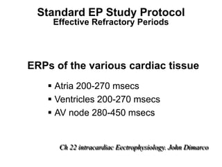
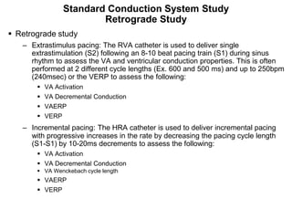
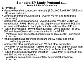
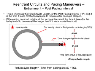
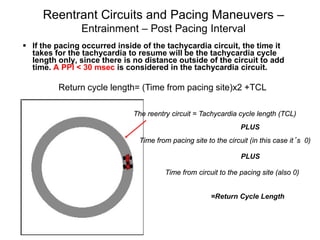
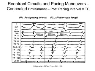
Electrophysiologic studies use pacing techniques like programmed electrical stimulation (PES) to evaluate cardiac properties. PES involves pacing the heart with drive trains and extrastimuli to measure refractory periods, conduction dynamics, and induce arrhythmias. Pacing can be unipolar or bipolar, and incremental, decremental, or with extrastimuli. Refractory periods like the effective refractory period and relative refractory period are measured using premature extrastimuli during pacing. These techniques provide important information about normal cardiac function and arrhythmia mechanisms.
Our concepts of heart disease are based on the enormous reservoir of physiologic and anatomic knowledge derived from the past 70 years' of experience in the cardiac catheterization laboratory.
As Andre Cournand remarked in his Nobel lecture of December 11, 1956, the cardiac catheter was the key in the lock.
By turning this key, Cournand and his colleagues led us into a new era in the understanding of normal and disordered cardiac function in huma
"𝑩𝑬𝑮𝑼𝑵 𝑾𝑰𝑻𝑯 𝑻𝑱 𝑰𝑺 𝑯𝑨𝑳𝑭 𝑫𝑶𝑵𝑬"
𝐓𝐉 𝐂𝐨𝐦𝐬 (𝐓𝐉 𝐂𝐨𝐦𝐦𝐮𝐧𝐢𝐜𝐚𝐭𝐢𝐨𝐧𝐬) is a professional event agency that includes experts in the event-organizing market in Vietnam, Korea, and ASEAN countries. We provide unlimited types of events from Music concerts, Fan meetings, and Culture festivals to Corporate events, Internal company events, Golf tournaments, MICE events, and Exhibitions.
𝐓𝐉 𝐂𝐨𝐦𝐬 provides unlimited package services including such as Event organizing, Event planning, Event production, Manpower, PR marketing, Design 2D/3D, VIP protocols, Interpreter agency, etc.
Sports events - Golf competitions/billiards competitions/company sports events: dynamic and challenging
⭐ 𝐅𝐞𝐚𝐭𝐮𝐫𝐞𝐝 𝐩𝐫𝐨𝐣𝐞𝐜𝐭𝐬:
➢ 2024 BAEKHYUN [Lonsdaleite] IN HO CHI MINH
➢ SUPER JUNIOR-L.S.S. THE SHOW : Th3ee Guys in HO CHI MINH
➢FreenBecky 1st Fan Meeting in Vietnam
➢CHILDREN ART EXHIBITION 2024: BEYOND BARRIERS
➢ WOW K-Music Festival 2023
➢ Winner [CROSS] Tour in HCM
➢ Super Show 9 in HCM with Super Junior
➢ HCMC - Gyeongsangbuk-do Culture and Tourism Festival
➢ Korean Vietnam Partnership - Fair with LG
➢ Korean President visits Samsung Electronics R&D Center
➢ Vietnam Food Expo with Lotte Wellfood
"𝐄𝐯𝐞𝐫𝐲 𝐞𝐯𝐞𝐧𝐭 𝐢𝐬 𝐚 𝐬𝐭𝐨𝐫𝐲, 𝐚 𝐬𝐩𝐞𝐜𝐢𝐚𝐥 𝐣𝐨𝐮𝐫𝐧𝐞𝐲. 𝐖𝐞 𝐚𝐥𝐰𝐚𝐲𝐬 𝐛𝐞𝐥𝐢𝐞𝐯𝐞 𝐭𝐡𝐚𝐭 𝐬𝐡𝐨𝐫𝐭𝐥𝐲 𝐲𝐨𝐮 𝐰𝐢𝐥𝐥 𝐛𝐞 𝐚 𝐩𝐚𝐫𝐭 𝐨𝐟 𝐨𝐮𝐫 𝐬𝐭𝐨𝐫𝐢𝐞𝐬."
[Note: This is a partial preview. To download this presentation, visit:
https://www.oeconsulting.com.sg/training-presentations]
Sustainability has become an increasingly critical topic as the world recognizes the need to protect our planet and its resources for future generations. Sustainability means meeting our current needs without compromising the ability of future generations to meet theirs. It involves long-term planning and consideration of the consequences of our actions. The goal is to create strategies that ensure the long-term viability of People, Planet, and Profit.
Leading companies such as Nike, Toyota, and Siemens are prioritizing sustainable innovation in their business models, setting an example for others to follow. In this Sustainability training presentation, you will learn key concepts, principles, and practices of sustainability applicable across industries. This training aims to create awareness and educate employees, senior executives, consultants, and other key stakeholders, including investors, policymakers, and supply chain partners, on the importance and implementation of sustainability.
LEARNING OBJECTIVES
1. Develop a comprehensive understanding of the fundamental principles and concepts that form the foundation of sustainability within corporate environments.
2. Explore the sustainability implementation model, focusing on effective measures and reporting strategies to track and communicate sustainability efforts.
3. Identify and define best practices and critical success factors essential for achieving sustainability goals within organizations.
CONTENTS
1. Introduction and Key Concepts of Sustainability
2. Principles and Practices of Sustainability
3. Measures and Reporting in Sustainability
4. Sustainability Implementation & Best Practices
To download the complete presentation, visit: https://www.oeconsulting.com.sg/training-presentations
Attending a job Interview for B1 and B2 Englsih learnersErika906060
It is a sample of an interview for a business english class for pre-intermediate and intermediate english students with emphasis on the speking ability.
Remote sensing and monitoring are changing the mining industry for the better. These are providing innovative solutions to long-standing challenges. Those related to exploration, extraction, and overall environmental management by mining technology companies Odisha. These technologies make use of satellite imaging, aerial photography and sensors to collect data that might be inaccessible or from hazardous locations. With the use of this technology, mining operations are becoming increasingly efficient. Let us gain more insight into the key aspects associated with remote sensing and monitoring when it comes to mining.
As a business owner in Delaware, staying on top of your tax obligations is paramount, especially with the annual deadline for Delaware Franchise Tax looming on March 1. One such obligation is the annual Delaware Franchise Tax, which serves as a crucial requirement for maintaining your company’s legal standing within the state. While the prospect of handling tax matters may seem daunting, rest assured that the process can be straightforward with the right guidance. In this comprehensive guide, we’ll walk you through the steps of filing your Delaware Franchise Tax and provide insights to help you navigate the process effectively.
Memorandum Of Association Constitution of Company.pptseri bangash
www.seribangash.com
A Memorandum of Association (MOA) is a legal document that outlines the fundamental principles and objectives upon which a company operates. It serves as the company's charter or constitution and defines the scope of its activities. Here's a detailed note on the MOA:
Contents of Memorandum of Association:
Name Clause: This clause states the name of the company, which should end with words like "Limited" or "Ltd." for a public limited company and "Private Limited" or "Pvt. Ltd." for a private limited company.
https://seribangash.com/article-of-association-is-legal-doc-of-company/
Registered Office Clause: It specifies the location where the company's registered office is situated. This office is where all official communications and notices are sent.
Objective Clause: This clause delineates the main objectives for which the company is formed. It's important to define these objectives clearly, as the company cannot undertake activities beyond those mentioned in this clause.
www.seribangash.com
Liability Clause: It outlines the extent of liability of the company's members. In the case of companies limited by shares, the liability of members is limited to the amount unpaid on their shares. For companies limited by guarantee, members' liability is limited to the amount they undertake to contribute if the company is wound up.
https://seribangash.com/promotors-is-person-conceived-formation-company/
Capital Clause: This clause specifies the authorized capital of the company, i.e., the maximum amount of share capital the company is authorized to issue. It also mentions the division of this capital into shares and their respective nominal value.
Association Clause: It simply states that the subscribers wish to form a company and agree to become members of it, in accordance with the terms of the MOA.
Importance of Memorandum of Association:
Legal Requirement: The MOA is a legal requirement for the formation of a company. It must be filed with the Registrar of Companies during the incorporation process.
Constitutional Document: It serves as the company's constitutional document, defining its scope, powers, and limitations.
Protection of Members: It protects the interests of the company's members by clearly defining the objectives and limiting their liability.
External Communication: It provides clarity to external parties, such as investors, creditors, and regulatory authorities, regarding the company's objectives and powers.
https://seribangash.com/difference-public-and-private-company-law/
Binding Authority: The company and its members are bound by the provisions of the MOA. Any action taken beyond its scope may be considered ultra vires (beyond the powers) of the company and therefore void.
Amendment of MOA:
While the MOA lays down the company's fundamental principles, it is not entirely immutable. It can be amended, but only under specific circumstances and in compliance with legal procedures. Amendments typically require shareholder
RMD24 | Retail media: hoe zet je dit in als je geen AH of Unilever bent? Heid...BBPMedia1
Grote partijen zijn al een tijdje onderweg met retail media. Ondertussen worden in dit domein ook de kansen zichtbaar voor andere spelers in de markt. Maar met die kansen ontstaan ook vragen: Zelf retail media worden of erop adverteren? In welke fase van de funnel past het en hoe integreer je het in een mediaplan? Wat is nu precies het verschil met marketplaces en Programmatic ads? In dit half uur beslechten we de dilemma's en krijg je antwoorden op wanneer het voor jou tijd is om de volgende stap te zetten.
Putting the SPARK into Virtual Training.pptxCynthia Clay
This 60-minute webinar, sponsored by Adobe, was delivered for the Training Mag Network. It explored the five elements of SPARK: Storytelling, Purpose, Action, Relationships, and Kudos. Knowing how to tell a well-structured story is key to building long-term memory. Stating a clear purpose that doesn't take away from the discovery learning process is critical. Ensuring that people move from theory to practical application is imperative. Creating strong social learning is the key to commitment and engagement. Validating and affirming participants' comments is the way to create a positive learning environment.
2. Pacing Methods: Programmed Electrical
Stimulation (PES)
PES is a pacing technique using an intermittent or
continuous introduction of an electrical current to
the intracardiac surface through an electrode
catheter.
Cells near the electrodes depolarize and begin a
wave of depolarization that propagates throughout
the heart.
This facilitates the evaluation of cardiac refractory
periods, conduction dynamics, automaticity and
arrhythmic mechanisms.
2
4. Programmed Electrical Stimulation
PES consists of three types of pacing:
– Incremental (burst)
– Decremental (ramp)
– Extrastimulus
PES is used to measure and evaluate ….
– Refractory periods
– Conduction properties
– Pattern of myocardial activation
– Tachycardia Characteristics
Initiation
Termination
Differentiation
4
5. Definitions and Types of PES
Pacing Drive Train – a series of 6-10 fixed
paced stimuli at a constant rate that are
separated by a pause. Referred to as “S1s”
(stimulus cycle length #1) .
Sensed S1 S1 S1 S1 S1 S1 S1 S1S2 S3 S4
DRIVETRAIN
5
6. Definitions and Types of PES
Incremental Pacing - is pacing the heart at a fixed
rate. The rate is increased (pacing interval
decreased) with each set of beats.
S1-S1 = 400 S1-S1 = 390 S1-S1 = 380 S1-S1 = 370
6
7. Definitions and Types of PES
Decremental Pacing – pacing at a progressively
increasing heart rate by decreasing the amount of
time between each paced beat. Used primarily to
induce or terminate tachycardias. It is also called
“ramp” pacing.
Click to start
Sns Sns Sns Sns S 1 S 1 S 1 S 1 S 1 Sns Sns Sns
7 TACHY.SENSE RAMP
8. Definitions and Types of PES
Exrastimulus Pacing
Sensed S1 S1 S1 S1 S1 S1 S1 S1S2
For the standard EP study
to test the refractory
periods, one extrastimulus Single extras
(S2) will be used. If a
second extrastimulus is
DRIVETRAIN
used, it is usually for
arrhythmia induction and is Sensed S1 S1 S1 S1 S1 S1 S1 S1S2 S 3
called “S3”. Up to 3 (S4)
extrastimuli (S2, S3, S4)
can be given in a standard Double extras
EPS. Any more than 3
extrastimuli would induce a
DRIVETRAIN
non-clinical arrhythmia.
That is, it could induce an Sensed S1 S1 S1 S1 S1 S1 S1 S1S2 S3 S4
arrhythmia in a normal
subject.
Triple extras
DRIVETRAIN
8
9. Common Extrastimulus Induction Protocol
Type of Basic Single extrastimuli Double extrastimuli (ms) Triple extrastimuli (ms)
arrhythmia cycle (ms)
length
(ms)
S1-S1 S1-S1 S1-S2 S1-S1 S1-S2 S2-S3 S1-S1 S1-S2 S2-S3 S3-S4
Atrial 600, 400 600, 400 600- 200 or 600, 400 600-200 or 600-200 or 600, 400 600-200 or 600-200 or 600-200 or
ERP in ERP in ERP in ERP in ERP in ERP in
10ms 10ms 10ms 10ms 10ms 10ms
decrements decrements decrements decrements decrements decrements
Ventricular 600, 400 600, 400 ERP + 60- 600, 400 ERP + 60- ERP + 60- 600, 400 ERP + 60- ERP + 60- ERP + 60-
200 or ERP 200 or ERP 200 or ERP 200 or ERP 200 or ERP 200 or ERP
in 10ms in 10ms in 10ms in 10ms in 10ms
in 10ms decrements decrements decrements decrements decrements
decrements
For triple extrastimuli (S4), the S1-S2 and S2-S3 may be reduced with either the S1-S2 being long and the S2-S3 being short or vice versa. They can also be
decreased simultaneously. Some arrhythmias are often easily induced by a short (S1-S2) - long (S2-S3) configuration.
9
10. Pacing Protocols in EPS
Typical Pacing Protocols
– Right Atrial Straight (Incremental) Pacing
– Decremental Atrial Pacing
– Programmed Atrial Stimuli with Atrial
Extrastimuli
– Right Ventricular Straight (Incremental)
Pacing
– Decremental Ventricular Pacing
– Programmed Ventricular Pacing with Single,
Double and Triple Extrastimuli
10
12. Absolute and Relative Refractory Periods
Absolute (Effective) refractory period - no matter how strong
the stimulus is, the cell can not depolarize.
Relative refractory period - if the stimulus is strong enough
(PAC, PVC or high pacing output) the cell may depolarize
12
13. Absolute and Relative Refractory Periods
The ventricular relative refractory period (RRP) falls around the
middle of the “T wave”, and this is called the vulnerable period.
The same occurs for the atrium. If a stimulus or PVC in the
ventricle or PAC in the atrium falls in this period, it may induce
either atrial fibrillation (if in the atrial RRP), or ventricular
tachycardia or ventricular fibrillation (if in the ventricular RRP).
13
14. Refractory Periods
Premature impulses are used to measure refractory periods of cardiac tissue. They are the:
• Effective refractory period (ERP) – Phase 2 - longest coupling interval that a
premature impulse fails to propagate through cardiac tissue = absolute refractory
period
• Cardiac cells cannot be depolarized during the ERP
• Coupling interval – time between the last paced impulse and premature impulse.
• Relative refractory period (RRP) – time from the end of the ERP to the beginning of
Phase 4 (Phases 3 & 4) – longest coupling interval that a premature impulse results in
slow conduction. Time when cells can be depolarized again with a strong enough
stimulus.
• If a cardiac cell is stimulated during the RRP, the resulting action potential has a
slower Phase 0 slope and the impulse propagates at a slower conduction velocity.
• Functional refractory period (FRP) – shortest time between 2 successive
conducted impulses (time when cells can be depolarized again - usually used
14 describe AV node function). The shortest output of any given input.
to
16. AV Node Conduction (Refractory) Curves
There are 2 main plots used to show the
conduction properties obtained during
programmed stimulation:
– A1-A2 versus H1-H2 and V1-V2.
This gives an assessment of the FRP of the AV
conduction system.
– A1-A2 versus A2-H2 and H2-V2 .
Allows to actually determine conduction times through
the AV conduction system.
rd
16 Josephson, ME. Clinical Cardiac Electrophysiology, Techniques and Interpretations (3
Edition), Lippincott, Williams and Wilkins, 2002, pp.47.
17. AV Node Conduction (Refractory) Curves
A1-A2 versus H1-H2 and V1-V2
The doctor will pace to determine the conduction properties of the AVN. The
conduction curve will look as below.
V1-V2
H1-H2
(msec) 700
A
600
C
Line of Identity
500
FRP
400
B
300 400 500 600 700
A1-A2
ERP (msec)
17
18. Responses to Atrial Extrastimuli
There are 3 main patterns of the response to atrial
stimuli:
– Type I – Most common and involves the impulse
propagation meeting a progressively greater delay in the
AV node without any change in the infranodal (His-
Purkinje) conduction. Thus, the AH interval prolongs, but
the HV interval does not. Block will occur in the AV node
or the atrium.
– Type II – Delay is initially noted in the AV node, but at
shorter coupling intervals (S1-S2), delay is noted in the
His-Purkinje system. However, block still usually occurs in
the AV node first, but may occur in the atrium or
occasionally in the His-Purkinje system.
– Type III – Least common and initially conduction slows in
the AV node, but at a critical S1-S2, a sudden and marked
prolongation occurs in the HV interval (His-Purkinje
system). Block first occurs in the His-Purkinje system.
rd
18 Josephson, ME. Clinical Cardiac Electrophysiology, Techniques and Interpretations (3
Edition), Lippincott, Williams and Wilkins, 2002, pp.46-47.
19. AV Node Conduction (Refractory) Curves
A1-A2 versus A2-H2 and H2-V2 – Type I Response
The doctor will pace to determine the conduction properties of the AVN. The
conduction curve will look as below.
400
A2-H2
H2-V2
300
(msec) 700
200
100
200 300 400 500 600
ERP A1-A2
19 (msec)
20. AV Node Conduction (Refractory) Curves
A1-A2 versus A2-H2 and H2-V2 – Type II Response
The doctor will pace to determine the conduction properties of the AVN. The
conduction curve will look as below.
400
A2-H2
H2-V2
300 (msec) 700
200
100
200 300 400 500 600
ERP A1-A2
20 (msec)
21. AV Node Conduction (Refractory) Curves
A1-A2 versus A2-H2 and H2-V2 – Type III Response
The doctor will pace to determine the conduction properties of the AVN. The
conduction curve will look as below.
400
A2-H2
H2-V2
300 (msec) 700
200
100
200 300 400 500 600
ERP A1-A2
21 (msec)
22. Types of Conduction Properties
Decremental Conduction
– Normal nodal tissue exhibits decremental conduction.
– A propagated impulse at a progressively decreasing
interval causes a progressive increase in the impulse
conduction delay.
(i.e. The increasing prematurity of the impulse = Slower
impulse conduction)
Non-Decremental Conduction
– Atrial and ventricular myocardium and most accessory
pathways (Kent) exhibit non-decremental conduction.
– There is no delay in the propagation of an impulse
through the tissue despite an increasing prematurity of an
impulse.
22 (i.e All or none conduction)
23. Conduction Properties – AV Decremental Conduction
With the AV decremental properties, as the pacing rate is increased,
eventually the rate of conduction will progressively slow, as seen by
progressively longer and longer AH intervals as the S1-S2 or S1-S1 pacing
interval is increased. This prolongation indicates the pacing has entered the
relative refractory period.
S1-S2
AH interval prolongs
23
24. AV Node Conduction Curve – AV Wenckebach
During incremental pacing Wenckebach occurs due to progressively
entering the relative refractory period (RRP) until a beat drops. The ERP
also prolongs as each stimulus enters deeper into the RRP.
Phase
0
Dropped beat
No “H” and “V”
S1
24 S1 S1 S1 S1
25. AV Node Conduction Curve – AV Wenckebach
AV Wenckebach is associated with:
Group beating
Progressively prolonging AH intervals
Prolonging AH
Grouped beats Dropped beats
intervals
25
26. AV Node Conduction Curve – AV Wenckebach
AH Intervals
Dropped beat
With Wenckebach there are grouped beats with gradual prolongation of the AH interval
until conduction to the ventricle eventually drops. Therefore only an occasional “A”
wave will not conduct to produce a “V” (see the dropped “V” above). This occurs as
pacing is hitting far into the relative refractory period.
26
28. Autonomic Nervous System
Increases in sympathetic tone increases
conduction velocity and decreases refractory
periods.
Increases in parasympathetic tone decreases
conduction velocity and increases refractory
periods.
28
30. Relative Refractory Period
The relative refractory period (RRP) is the period of
time when only a stimulus greater than normal
results in an action potential. The RRP is the
longest S1-S2 coupling interval (premature impulse)
that causes prolonged conduction of the S2 relative
to the basic cycle length (S1-S1). The start of the
RRP is just after the end of the full recovery period
where the conduction of the S2 and S1 is the same
(i.e. the RRP will have slower conduction for S2
than for S1).
30
32. Refractory Periods: RRP
Physiology of the Heart, Katz, Ch.14; p. 248.
RRP
Relative, (phase 3,4) (RRP).
• Time when cells can be depolarized again with a strong enough
stimulus. The longest premature coupling interval at which delay
in conduction (prolongation of conduction) occurs.
32
33. Relative Refractory Periods
If a stimulus falls in the relative refractory period, and if it is strong
enough the cell will depolarize. However, depolarization (slope of
phase 0) will become slower and slower the closer you approach the
ERP. For the AV node this is expressed as a progressively
lengthening AH interval as you pace closer and closer to the ERP.
33
35. Relative Refractory Period: Antegrade
Antegrade Relative Refractory Periods:
Atrial RRP or ARRP:
• The longest S1 - S2 interval at which the S2-A2 interval
exceeds the S1-A1. This is called latency. (-ms)
Atrioventricular Nodal RRP or AVNRRP:
• The longest A1 - A2 at which the A2-H2 interval exceeds the
A1-H1. (-ms)
His Purkinje System RRP or HPRRP:
• The longest H1 - H2 at which the H2-V2 interval exceeds the
H1-V1 or results in an aberrant QRS complex. (-ms)
rd
35 Josephson, ME. Clinical Cardiac Electrophysiology, Techniques and Interpretations (3
Edition), Lippincott, Williams and Wilkins, 2002, pp.39.
37. Latency (ARRP)
Latency is defined as the time difference (delay)
between the initiation of a stimulus and the observed
response to that stimulus. As an extra stimulus is
introduced with shorter coupling intervals, the ability
of the targeted tissue to accept and conduct this
impulse becomes more compromised. Increasing the
rate of pacing results in less time for recovery of tissue
(shortening of the action potential). This is especially
true of AV nodal cells.
37
39. Relative Refractory Period: Retrograde
Retrograde Relative Refractory Periods:
Ventriculoatrial RRP or VARRP:
• The longest S1 - S2 interval at which the S2-A2 interval
exceeds the S1-A1. (-ms)
Ventricular RRP or VRRP:
• The longest S1 - S2 interval at which the S2-V2 interval
exceeds the S1-V1. This is called latency. (-ms)
Josephson, ME. Clinical Cardiac Electrophysiology, Techniques and Interpretations (3rd Edition),
39 Lippincott, Williams and Wilkins, 2002, pp.39.
42. Functional Refractory Period (FRP)
The minimum interval between two consecutively
conducted impulses through the cardiac tissue.
The FRP of the AV node can vary, but it tends to
decrease with decreasing cycle lengths.
For atrial and ventricular tissue it tells you how fast
that tissue can conduct on a beat to beat basis.
42
44. Functional Refractory Period: Antegrade
Antegrade Functional Refractory Periods:
Atrial FRP or AFRP
The shortest A1 - A2 in response to any S1- S2.
Atrioventricular Nodal FRP or AVNFRP
The shortest H1- H2 in response to any A1-A2 (320-
680ms).
Atrioventricular Conduction System FRP or AVFRP
The shortest V1 - V2 in response to any S1- S2.
Josephson, ME. Clinical Cardiac Electrophysiology, Techniques and Interpretations (3rd Edition),
44 Lippincott, Williams and Wilkins, 2002, pp.39.
46. Functional Refractory Period: Retrograde
Retrograde Functional Refractory Periods:
Retrograde Atrioventricular Nodal FRP or AVNFRP
The shortest A1- A2 in response to any S1-S2.
Ventriculoatrial Conduction System FRP or VAFRP
The shortest A1- A2 in response to any H1-H2.
Ventricular FRP or VFRP
The shortest V1-V2 in response to any S1-S2 or
shortest V1-V2 as measured on the surface leads.
Josephson, ME. Clinical Cardiac Electrophysiology, Techniques and Interpretations (3rd Edition),
46 Lippincott, Williams and Wilkins, 2002, pp.39.
50. Effective Refractory Period
Effective or absolute, (phase
2) (ERP) is the longest
amount of time when cells
cannot be depolarized
again. The longest input that
fails to conduct.
Atria 200-270 msecs
Ventricles 200-270 msecs
AV node 280-450 msecs
Ch 22 intracardiac Eectrophysiology. John
Dimarco
S1 S2
50 Physiology of the Heart, Katz, Ch.14; p. 248
51. Effective Refractory Period Measurement
The ERP is measured using extrastimulus pacing with an
early beat inserted following 8-10 beats at a fixed rate
(pacing train). The pacing train allows the refractoriness to
stabilize. This stabilization usually occurs after 3-4 beats.
Also the current strength of the stimulus will influence the
ERP. The greater the current strength, the shorter the ERP
(in msec). The ERP will continue to shorten as the current
increases, but eventually becomes fixed at further increases.
Increasing the current strength to 10 mA usually results in
shortening the ERP by 30 msec.
51 •(Josephson, ME. Clinical Cardiac Electrophysiology, Techniques and Interpretations (3rd Edition), Lippincott,
Williams and Wilkins, 2002, pp.39-40.)
52. ERP: Effect of Current Strength
Atrial and ventricular ERPs decrease with the increased current
strength of the impulse. Normal ERP measurements are taken at twice
the diastolic threshold, but if the current strength is increased up to
10mA, the ERP will shorten on average by 30msec. The important thing
is to be consistent with the method you use.
10
8
Current (mA)
6
4
2
0
180 200 220 240
VERP (msec)
52
Josephson, M. Clinical Cardiac Electrophysiology, Techniques and Interpretations (3rd Edition), Lippincott, Williams and Wilkins, 2002, pp. 39-40.
53. Affect of Pacing on the ERP
ERP of atrial and ventricular tissue shortens
with pacing, allowing introduction of
premature beats.
ERP of AV node lengthens with pacing, and
results in blocking of conduction to the
ventricles.
53
54. ERP Response to Different Cycle Lengths
The ERPs of ventricular tissue and the His-Purkinje system differ in their response to different drive
cycle lengths and extrastimuli (abrupt cycle length changes). Ventricular refractoriness demonstrates
the cumulative effect of the preceding cycle lengths (several beats of a drive cycle), whereas the His-
Purkinje system is effected greatly by the immediately preceding cycle length. Thus a change from a
long to short cycle length will shorten both the His-Purkinje and ventricular ERPs, but a short to long
cycle length will drastically prolong the His-Purkinje ERP, but will have only a slight effect if at all on
the ventricular ERP. This is even more exaggerated if only a single extrastimulus is used. Below shows
the effect on the His-Purkinje system.
His-Purkinje System
A. Constant CL
600 600 600 600 Cycle length (CL)
Action Potential Duration
350 350 350 350 350 (APD)
250 250 250 250 Diastolic Interval
B. Long to short
800 800 600
450 450 450 300
350 350 150
400 400 400 600 Effect on His-
C. Short to Long
Purkinje System,
but not on the
250 250 250 250 400 VERP
150 150 150 350
54
Josephson, M. Clinical Cardiac Electrophysiology, Techniques and Interpretations (3rd Edition), Lippincott, Williams and Wilkins, 2002, pp. 40-44.
55. ERP Response to Multiple Stimuli
The determinate factor of the ventricular ERP appears to be the diastolic interval. The
ventricular refractory period (VERP) following one extrastimulus is shorter than that
following two. In A, S2 hits making the diastolic interval only 40ms. Because it is short,
it makes the resultant VERP shorter at 180ms. In B, the same thing occurs after S2,
but when S3 is placed at the same cycle length as S1-S2 (260ms), because the
VERP was only 180ms, the diastolic interval becomes 80ms. Since that is longer than
the previous 40ms one, now the VERP is longer at 195ms. If this were the His-
Purkinge system, the ERP both after the S2 and S3 would have been much more
prolonged.
40ms
Diastolic Interval: 180ms 180ms
VERP: 220ms 220ms 220ms 180ms
Coupling Interval: 400ms 400ms 260ms
A
S1 S1 S1 S2
40ms 80ms
Diastolic Interval: 180ms 180ms
VERP: 220ms 220ms 220ms 180ms 195ms
Coupling Interval: 400ms 400ms 260ms 260ms
B
S1 S1 S1 S2 S3
Josephson, M. Clinical Cardiac Electrophysiology, Techniques and Interpretations (3rd Edition), Lippincott, Williams and Wilkins, 2002, pp.44.
55
56. Effective Refractory Periods: Antegrade
Antegrade Effective Refractory Periods:
Atrial ERP or AERP:
The longest S1 - S2 that fails to capture the atrium (150-
360ms)
Atrioventricular Nodal ERP or AVNERP:
The longest A1 - A2 measured from the His Bundle
electrogram that fails to conduct to the His (230-430ms)
Atrioventricular conduction system (AVCS) ERP or AVERP:
The longest S1 - S2 that fails to result in a ventricle
depolarization
Josephson, ME. Clinical Cardiac Electrophysiology, Techniques and Interpretations (3rd Edition),
56 Lippincott, Williams and Wilkins, 2002, pp.39.
57. Atrial and AV Node Effective Refractory Periods
V1 V2
S1-S2 = 290ms
A1-A2 = 300ms
S1 H1 S2 H2
A1 A2 A2 A2-H2 = 60ms
S2-A2 = 10ms
V1 V
S1-S2 = 270ms
AVNERP A1-A2 = 285ms
S1 H1 S2 No H2 H A2-H2 = 90ms
A1 A2 A S2-A2 = 15ms
V1 V
S1-S2 = 250ms
A1-A2 = 280ms
No A2
AERP H
A2-H2 = NA
S1 H1 S2
A1 A S2-A2 = NA
Atrial ERP or AERP: The longest S1 - S2 that fails to capture the atrium (150-
360ms)
Atrioventricular Nodal ERP or AVNERP: The longest A1 - A2 measured from the
57 His Bundle electrogram that fails to conduct to the His (230-430ms)
58. AV Conduction system Effective Refractory Period
V1 V2
S1-S2 = 310ms
A1-A2 = 315ms
S1 H1 S2 H2 A2-H2 = 50ms
A1 A2 A2 S2-A2 = 5ms
V1 V
Recovery of S1-S2 = 270ms
AVERP sinus beat A1-A2 = 100ms
S1 H2 No V H A2-H2 = NA
H1 S2
A1 A2 A S2-A2 = 15ms
V1 V
AVERP Recovery of S1-S2 = 270ms
sinus beat A1-A2 = 285ms
S1 No H2 H A2-H2 = NA
H1 S2
A1 A2 A S2-A2 = 15ms
Atrioventricular conduction system (AVCS) ERP or AVERP: The longest S1 -
58 S2 that fails to result in a ventricle depolarization
59. Effective Refractory Periods: Retrograde
Retrograde Effective Refractory Periods:
Retrograde His Purkinje System ERP or Retrograde HPERP:
The longest S1 - S2 or V1-V2 in which S2 or V2 block below the
bundle of His. Can only measure if H2 is recorded before the retrograde
block.
Retrograde AV Node ERP or Retrograde AVNERP:
The longest S1 - H2 or H1-H2 that H2 fails to conduct to the atrium
Ventriculoatrial Conduction System (VACS) ERP or VAERP:
The longest S1 - S2 that fails to conduct to the atrium
Ventricular ERP or VERP:
The longest S1 - S2 that fails to capture the ventricle (170-290ms)
Josephson, ME. Clinical Cardiac Electrophysiology, Techniques and Interpretations (3rd Edition),
59 Lippincott, Williams and Wilkins, 2002, pp.39.
60. Retrograde AV Node Effective Refractory Period
V1 V2
S1-S2 = 290ms
V1-V2 = 300ms
S1 H2 H2-A2 = 60ms
H1 S2
A1 A2 H1-H2 = 295ms
S1-H2 = 340ms
V1 V2 S1-S2 = 270ms
V1-V2 = 285ms
H2-A2 = 90ms
S1 H1 S2 H2
A2
H1-H2 = 280ms
A1
S1-H2 = 335ms
V1 V2 S1-S2 = 250ms
Retrograde AVNERP V1-V2 = 280ms
H2-A2 = NA
S1 H1 S2 H2 H1-H2 = 265ms
A1 No A2 S1-H2 = 330ms
Retrograde AV Node ERP or Retrograde AVNERP: The longest S1 - H2 or H1-
60 H2 that H2 fails to conduct to the atrium
61. VA Conduction System (VACS) ERP: Block in the AV Node an His-
Purkinje System
V1 V2
S1-S2 = 290ms
V1-V2 = 300ms
S1 H1 S2 H2 H2-A2 = 60ms
A1 A2 S2-V2 = 10ms
V1 V2
S1-S2 = 250ms
VAERP V1-V2 = 280ms
S1 H1 S2 H2
A1 No A2 H2-A2 = NA
S2-V2 = 30ms
S1-S2 = 250ms
V1 V2 V1-V2 = 280ms
VAERP S1-V1 = 5ms
S2-V2 = 20ms
S1 H1 S2 No H2 S1-H1 = 40ms
A1 No A2 S2-H2 = NA
Ventriculoatrial Conduction System (VACS) ERP or VAERP: The longest S1 - S2 that fails
to conduct to the atrium
61
Ventricular ERP or VERP: The longest S1 - S2 that fails to capture the ventricle (170-290ms)
62. Ventricular Effective Refractory Period
V1 V2
S1-S2 = 270ms
V1-V2 = 285ms
S1 H1 S2 H2 H2-A2 = 90ms
A1 A2
S2-V2 = 15ms
V1 V2
S1-S2 = 250ms
V1-V2 = 280ms
S1 H1 S2 H2 No A2 H2-A2 = NA
A1 S2-V2 = 30ms
V1 V
S1-S2 = 230ms
VERP V1-V2 = NA
H H2-A2 = NA
S1 H1 S2 No V2
A1 A S2-V2 = NA
Ventricular ERP or VERP: The longest S1 - S2 that fails to capture the ventricle
62 (170-290ms)
63. Performing a Basic EP Study
Programmed Electrical Stimulation
Baseline EGM Recordings
Refractory Periods
Sinus Node Recovery Time (SNRT)
Sinoatrial Conduction Time (SACT)
Basic EP Tasks
63
64. What is an EP Study?
Electrical stress test
An invasive study to assess the
heart’s electrical conduction system
Patient under conscious sedation
Often classified outpatient
Done in EP lab, part of cardiac cath labs
64
65. Why Conduct an EP Study?
To evaluate conduction system function
To confirm supraventricular tachycardia
To evaluate ventricular tachyarrhythmias
To classify the extent of bradycardia
To test efficacy of antiarrhythmic drugs
To test efficacy of implanted devices
65
67. Which Type of EP Study?
Clinical Presentation Recommended Study
Documented SVT or Comprehensive EPS
atrial flutter with ablation
Suspected SVT Comprehensive EPS
Syncope Tilt, Baseline EPS, or
loop recorder
Nonsustained VT Baseline EPS
Suspected brady Baseline EPS only if VT
suspected
67
68. EP Study Outcomes
EP Study
Pharmacologic Device
Device Surgical
Catheter No
Therapy Implant Ablation Therapy
Therapy Therapy Therapy
68
69. Basic Steps in an EP Study
Equipment in room and functional
Patient info in recording system
Check plan with physician
Gather sheaths, catheters, connectors
Patient in room and prepped
Prep sterile table, open products
Sedate patient
Catheters placed with acceptable thresholds
Baseline intervals and stimulation protocols
Ablate, wait, re-test
Pull and hold
69
71. Electrophysiology Study
Measurement of baseline conduction intervals
Atrial Pacing
- Assessment of SA nodal automaticity and
conductivity
- Assessment of AV nodal conductivity and
refractoriness
- Assessment His-Purkinjie system conductivity and
refractoriness
- Assessment of atrial refractoriness
71
73. Catheters used in a Conduction
System Study
Quadripolar for HRA Evaluate sinus node function
Evaluate antegrade AV node
Quadripolar for HBE conduction
Quadripolar for RVA Evaluate retrograde AV node
conduction
73
74. Catheters used in a EP Study
Catheters used in standard EP studies:
Quadripolar in the HRA (usually fixed curve)
Quadri, hexa, octa, or decapolar at the HBE
(fixed curve or steerable)
Quadripolar in the RVA (usually fixed curve)
Hex, octa, or decapolar in the CS (fixed curve
or steerable)
74
75. Catheters used in SVT and VT Studies
Catheters used in SVT studies:
Quadripolar in the HRA (usually fixed curve)
Quadri, hexa, octa, or decapolar at the HBE (fixed curve or
steerable)
Quadripolar in the RVA (usually fixed curve)
Hex, octa, or decapolar in the CS (fixed curve or steerable)
Steerable large tip (4mm) mapping catheter
Catheters used in VT studies:
Quadripolar in the HRA (sometimes omitted)
Quadripolar (most common) at the HBE (fixed or steerable)
Quadripolar in the RVA (steerable is common so that it can
be moved to the RVOT)
Steerable large tip (4mm) mapping catheter
75
76. Standard Conduction System Study
Evaluate sinus node function
Sinus node recovery time (SNRT)
Sino-atrial conduction time (SACT)
Evaluate antegrade AV node conduction
AV Decremental Properties
AVNERP
AERP
AV Wenckebach cycle length (Incremental pacing only)
Evaluate retrograde AV node conduction (S1S2
and Incremental pacing)
VAERP
VERP
VA Wenckebach cycle length (Incremental pacing only)
76
77. Standard EP Study Protocol
Atrial Pacing
Pacing spike
A wave
Atrial pacing is performed with the HRA catheter to determine
the following:
– AV decremental properties
– AVNERP
– AV Wenckebach cycle length
77
– AERP
78. Standard Conduction System Study -
Antegrade Stimulation
For SA node evaluation two tests are performed
– SNRT
– SACT
If just one of these tests are performed, the evaluation of the
SA node may not be accurate, therefore it is recommended to
perform both
Since the autonomic nervous system can highly influence
these tests, it is recommended to perform a pharmacological
blockade to observe the true state of the SA node
– Atropine to eliminate the parasympathetic influence
– Propranolol to eliminate the sympathetic influence
Depending on the results of these tests, a pacemaker may be
implanted, so a correct evaluation should be made
78
79. Standard Conduction System Study – Sinus Node
Recovery Time (SNRT)
Sinus node recovery time (SNRT) – time it takes for the SA node to recover from overdrive
suppression of normal automaticity.
Test: To suppress SA nodal automaticity, overdrive pacing impulses are delivered via
the HRA at a rate faster than the intrinsic sinus rate at a constant rate for at least 30
seconds; then abruptly stopped and the SNRT measured. The SNRT is the longest
pause between the last paced beat and the first intrinsic beat after overdrive pacing
ends. SNRT measurements are typically taken at 800, 700, 600, 500, 450, 400, 350
and possibly 300 ms intervals. The longest interval observed during recovery is the
SNRT. An SNRT longer than 1,500 ms is considered abnormal.
Since the first cycles after the sinus node recovery are usually slightly longer than the
BCL, either a corrected sinus node recovery time (CSNRT) or an SNRT:BCL ratio is
used as below:
CSNRT = SNRT – BCL A CSNRT longer than 525 ms is considered abnormal.
SNRT / BCL x 100%. A ratio greater than 160% is considered abnormal.
79
80. Standard Conduction System Study – Sinus Node
Recovery Time (SNRT)
Sinus node recovery times (SNRT's)
A A A1 A1 A1 A2 A3
HRA
SCL
S1 S1 SNRT
SNRT=A1A2 (NORMAL < 1500 MSEC)
80 CSNRT=A1A2-SCL (NORMAL < 525 MSEC)
81. Standard Conduction System Study – Sinoatrial
Conduction Time (SACT)
SA Node (with pacemaker cells)
Transitional
cells
Last pacing Conduction from the
impulse atrium into the SA
node
Conduction from the SA
node to the atrium
Sinoatrial conduction time (SACT) – time it takes for a sinus impulse to conduct
through perinodal (surrounding) atrial tissue
When SA node disease (sick sinus syndrome) occurs, it is due to poor conduction
in the transitional cells and not failure of the pacemaker cells firing
A prolonged SACT suggests sinus exit block.
81
82. Standard Conduction System Study – Sinoatrial
Conduction Time (SACT)
SA Node (PAcells) Transitional
cells
Conduction from the Conduction from the SA node to
atrium into the SA node the atrium
A A
First sinus A wave
Last pacing spike
Return cycle
A SCL A
Pace from the HRA catheter at a rate slightly above the sinus rate for 30 - 60
seconds and then stop abruptly and measure from the last pacing spike to the
82 first sinus A wave
83. Standard Conduction System Study – Sinoatrial
Conduction Time (SACT)
SA Node (PAcells) Transitional
cells
A A
Return cycle
A SCL A
SACT = the return cycle (last S1 to the first sinus A wave) minus the SCL and then
divided by 2 (i.e. A + A)
*SCL = A-A interval measured on the HRA catheter in sinus rhythm
83 A = SACT (normal 50-125ms)
84. Standard Conduction System Study – Antegrade
Extrastimulus Pacing
After completing the SA node evaluation, the
doctor will use both extrastimulus pacing and
incremental pacing
Both antegrade (atrial pacing) and
retrograde (ventricular pacing) studies will be
performed.
84
85. Standard EP Study Protocol
Antegrade Study
Antegrade study
– Extrastimulus pacing: The HRA catheter is used to deliver single
extrastimulation (S2) following an 8-10 beat pacing train (S1) during
sinus rhythm to assess the AV node and atrial conduction properties.
This is often performed at 2 different cycle lengths (Ex. 600 and 500
ms) and up to 300bpm (200ms) or the AERP to assess the following:
AV Activation
AV Decremental Conduction
AVNERP
AERP
– Incremental pacing: The HRA catheter is used to deliver
incremental pacing with progressive increases in the rate by
decreasing the pacing cycle length (S1-S1) by 10-20ms decrements to
assess the following:
AV Activation
AV Decremental Conduction
AV Wenckebach cycle length
AVNERP
85
AERP
86. Standard EP Study Protocol
AV Decremental Conduction
With the AV decremental property, as the pacing rate is increased, eventually the rate
of conduction will progressively slow, as seen by progressively longer and longer AH
intervals as the S1-S2 or S1-S1 pacing interval is increased. This prolongation
indicates the pacing has entered the releative refractory period.
S1-S2
AH interval prolongs
86
87. Standard EP Study Protocol
AV Wenckebach
AH Intervals
Dropped beat
With Wenckebach there are grouped beats with gradual prolongation of the AH interval
until conduction to the ventricle eventually drops. Therefore only an occasional “A”
wave will not conduct to produce a “V” (see the dropped “V” above). This occurs as
pacing is hitting far into the relative refractory period.
87
88. Standard EP Study Protocol
AVNERP
Pacing spike
A
V No His or “V”
The ERP of the AV node is reached when conduction from the atrium
to the ventricle is blocked due to reaching the refractory period of the
AV nodal tissue. This would be evidenced by an “A” wave after the
pacing spike not followed by a His potential or a “V” wave. AVNERP =
280 - 450 msecs
88
89. Standard EP Study Protocol
AVNERP
To identify the ERP of the AV Node a series of programmed stimulation trains are conducted to
find the longest A1-A2 interval that fails to conduct to the His. Identifying the ERP of other
cardiac tissues is done in the same fashion:
Atrial ERP (AERP): The longest S1 - S2 that fails to capture the atrium
Ventricular ERP (VERP): The longest S1 - S2 that fails to capture the ventricle.
ERP of the AV Node
This is the longest A1-A2 that fails to conduct
89 This A1-A2 is longer but it DOES conduct
145
90. Standard EP Study Protocol
AERP
No local atrial
Pacing “spike” electrogram AERP
90 AERP = 200 - 270 msecs
92. Standard EP Study Protocol
Effective Refractory Periods
ERPs of the various cardiac tissue
Atria 200-270 msecs
Ventricles 200-270 msecs
AV node 280-450 msecs
Ch 22 intracardiac Eectrophysiology. John Dimarco
92
93. Standard EP Study Protocol
AH Jump
AH = 80msec
AH = 90msec
AH = 180msec
This sequence is showing evidence of what?
93
94. Standard Conduction System Study
Retrograde Study
Retrograde study
– Extrastimulus pacing: The RVA catheter is used to deliver single
extrastimulation (S2) following an 8-10 beat pacing train (S1) during sinus
rhythm to assess the VA and ventricular conduction properties. This is often
performed at 2 different cycle lengths (Ex. 600 and 500 ms) and up to 250bpm
(240msec) or the VERP to assess the following:
VA Activation
VA Decremental Conduction
VAERP
VERP
– Incremental pacing: The HRA catheter is used to deliver incremental pacing
with progressive increases in the rate by decreasing the pacing cycle length
(S1-S1) by 10-20ms decrements to assess the following:
VA Activation
VA Decremental Conduction
VA Wenckebach cycle length
VAERP
VERP
94
95. Standard EP Study Protocol
Retrograde Conduction Study
– Right Ventricular Straight Pacing
performed to
Check and set pacing thresholds
Check to see if the AV Node works backwards (retrograde conduction)
Check to see if there is an accessory pathway with retrograde
conduction (if no conduction can go retrograde up the normal
conduction system, yet you see retrograde conduction, then it means
there is an accessory pathway)
Do “rescue” pacing
Terminate or induce tachycardias
95
96. Standard EP Study Protocol
Retrograde Conduction Study – Ventricular Pacing
V A
VA
In this example pacing is being performed from the right
ventricular apex (RVA). Therefore you will first have a “V”
wave. Conduction will then conduct up the conduction system
resulting in a His potential and then an “A” wave. This is
called retrograde conduction. However, although it is a
normal phenomenon, not everyone has retrograde
96
conduction.
97. Standard EP Study Protocol
Retrograde Conduction Study – VA Block
V A V A V A V V A V
No “A” wave
Note that on the 4th and 6th beats no “A” wave follows the
“V” wave. This is called VA block.
97
98. Standard EP Study Protocol
Retrograde Conduction Study – VA Decremental Conduction
V HA V H A
Just as when you pace faster and faster from the atrium, when you pace at faster and
faster rates in the ventricle, you will have decremental conduction. That is, as you
pace faster and faster, the VA or HA interval will progressively prolong the faster you
go. This is because as you begin to enter the relative refractory period (RRP) of the
AV node, conduction begins to slow. The further into the RRP you pace, the slower
the conduction. In the example above, you can see that the VA and HA (not easily
seen) widened with the shorter (faster) pacing interval.
98
99. Standard EP Study Protocol
Retrograde Conduction Study – VERP
The ventricular ERP
(VERP) is reached when
you pace at a rate faster VERP
than the absolute
refractory period of the
ventricular tissue. This
would be evidenced by
a pacing spike not No local ventricular
electrogram
followed by a “V” wave.
Consequently there
would be no His
potential or “A” wave. Pacing “spike”
99 VERP = 200 - 270 msecs
101. Standard EP Study Protocol Cont. –
Arrhythmia Induction - SVT
1. 1 or 2 extrastimuli (S2 and S3) during SR from the RV apex
2. 1 or 2 extrastimuli (S2 and S3) during ventricular pacing (S1) at
100, 120 and 150 bpm (600, 500 and 400msec) from the apex
3. Incremental pacing from RV apex up to 250bpm (240msec) in
10-20msec decrements
4. 1 or 2 extrastimuli (S2 and S3) during SR from the HRA
5. 1 or 2 extrastimuli (S2 and S3) during atrial pacing (S1) at 100,
120, and 140 bpm (600,500,400msec) from the HRA
6. Incremental pacing from the HRA up to Wenckebach or 300
bpm (200msec), or until an arrhythmia is initiated in 10-20msec
decrements
7. Repeat steps 4-6 from the CS or left atrium
8. If not inducible with above give an isoproterenol infusion at a
rate of 1 to 6 µg/min to increase patients’ heart rate to at least
20% above the resting sinus rate or shorten the sinus CL to
450 msec and repeat steps 1-7
101
102. Standard EP Study Protocol
Arrhythmia Induction - VT
Atrial Protocol
1.1 extrastimuli (S2) during SR from the HRA
2.1 extrastimuli (S2) during atrial pacing at 100, 120 and 150 bpm (600, 500
and 400msec) from the HRA
3.Incremental pacing from the HRA up to the Wenckebach point, or 300
bpm (200msec), or initiation of SVT in 10-20msec decrements
Ventricular Protocol
1.1 - 2 extrastimuli (S2 and S3) during SR from the RV apex
2.1 - 2 extrastimuli during ventricular pacing at 100, 120 and 150 bpm (600,
500 and 400msec) from the RV apex
3.Incremental pacing from RVA up to 250bpm (240msec) in 10-20msec
decrements
4.3 extrastimuli (S2, S3 and S4) during SR from the RV apex
5.3 extrastimuli (S2, S3 and S4) during ventricular pacing at 100, 120 and
150 bpm (600, 500 and 400msec) from the RV apex
6.Repeat steps 1-5 from the right ventricular outflow tract
7.If not inducible with above give an isoproterenol infusion starting at a rate
102
of 2.5µg/min to increase patients’ heart rate to at least 20% above the
resting rate and repeat steps 1-6
103. Standard EP Study Protocol Cont. –
Arrhythmia Induction
In an EP study various types of pacing are used to induce the arrhythmias so that it
can be evaluated for its type and origin. In the example above a single (S2)
extrastimulus is used to induce the arrhythmia.
103
104. Standard EP Study Protocol Cont. –
Basic EP Tasks - Summary
EP Protocol:
• Measure baseline conduction intervals (BCL, IACT, AH, HV, QRS and
QT) in sinus rhythm
• Ventricular extrastimulus testing (VAERP, VERP, and retrograde
conduction)
• Incremental ventricular pacing (VA conduction, VAERP, VERP, VA
Wenckebach, FRP) - Pace at a rate slightly faster than the BCL and
increase until VA block. Pacing is typically no faster than 240 ms.
• PES in the ventricle (arrhythmia induction) - Drive train (S1) of 600,
500 and then 400 ms with extrastimuli until the VERP.
• Ventricular burst pacing (fixed, incremental or decremental – arrhythmia
induction).
• Atrial extrastimulus testing to measure the AV nodal and atrial
refractory periods.
• Incremental atrial pacing to assess AV and atrial conduction
(AVNERP, AV Wenckebach, AERP)- Pace at a rate slightly faster than
the BCL and decrease until AV block, but not faster than 200 ms.
• PES in the atrium (arrhythmia induction) - Drive train (S1) of 600, 500
and 400 ms with extrastimuli.
• Atrial burst pacing (fixed, incremental or decremental-arrhythmia
104 induction).
106. Reentry Requirements
Reentry circuits consist of a fast
pathway and slow pathway and
reentry requires an area of “slow” This is a longer path to this point...
conduction with a short refractory
period
– this could be caused by:
The AV Node;
An area of disease;
Or, simply a physically longer path
(like this example).
The fast pathway has fast
conduction, but a long refractory
period
– This can be the:
Fast pathway of the AV node
Accessory Pathway
Atrial tissue
Or a shorter path (as in the example)
Note how the wavefront cancels out
in the longer path (slow pathway) …than this one
106
107. Requirements for Reentry
“Sinus” “Reentry”
http://rezidentiat.3x.ro/eng/tulbritmeng.htm
Two limbs joined at their ends The other conducts faster but has
One conducts more slowly but a longer refractory period
107
has a shorter refractory period Unidirectional block in one limb
108. Reentry Requirements
Reentry requires
an area of
unidirectional
block-
– this also can come
from the AV Node
or disease, as well
as normal
variations in
refractoriness in
the presence of an
abnormal structure
(bypass tract).
108
109. Reentry Requirements
Reentry
requires a
complete circuit
that has both an
area of “slow”
conduction and
Unidirectional
block in it.
109
110. Terminating a Reentrant Circuit
Pacing
Pharmacological (Ex. Adenosine)
Ablation…
– Eliminates the complete circuit.
110
111. Reentrant Circuits and Pacing Maneuvers –
Resetting and Advancing the Tachycardia
“Resetting” or “Advancing” a tachycardia:
If you can pace faster than the tachycardia and speed the tachycardia up to
the pacing rate with one or more beats (entrainment) thus resetting or
advancing the tachycardia, then the mechanism is reentry.
111
113. Reentrant Circuits and Pacing Maneuvers –
Entrainment
Entrainment:
– The placement of several pacing impulses
into a tachycardia circuit that does not
terminate it.
The intent of entrainment is to determine
if the pacing site is in the tachycardia
circuit…
If the pacing site is in the circuit, it might
be an effective ablation site
113
114. Reentrant Circuits and Pacing Maneuvers –
Entrainment
Entrainment is continuous pacing during a tachycardia
that accelerates the activation to the pacing cycle
length and does not terminate the arrhythmia.
The ability to entrain a tachycardia supports reentry as
the tachycardia mechanism.
Entrainment pacing can occur outside of or within the
actual tachycardia circuit.
If it occurs outside the circuit, the ECG will be a
combination of the tachycardia morphology and what
the morphology would look like when pacing in normal
sinus rhythm (fusion).
If entrainment occurs within the circuit, the ECG
morphology remains constant (concealed entrainment).
114
115. Reentrant Circuits and Pacing Maneuvers –
Entrainment – Pacing with Fusion
This is a demonstration of pacing with fusion.
115
116. Reentrant Circuits and Pacing Maneuvers –
Entrainment – Pacing with Concealed Entrainment
This is a demonstration of pacing with concealed
entrainment.
116
117. Reentrant Circuits and Pacing Maneuvers –
Entrainment – Post Pacing Interval
This is known as the Return Cycle Length, or the Post Pacing Interval (PPI) and it
is the time it takes for the tachycardia to resume after pacing is stopped.
If the pacing occurred outside of the tachycardia circuit, the time it takes for the
tachycardia to resume will be longer than if it were inside the circuit.
= pacing site The reentry circuit = Tachycardia cycle length (TCL)
PLUS
Time from pacing site to the circuit
PLUS
Time from circuit to the pacing site
=Return Cycle Length
117 Return cycle length= (Time from pacing site)x2 +TCL
118. Reentrant Circuits and Pacing Maneuvers –
Entrainment – Post Pacing Interval
If the pacing occurred inside of the tachycardia circuit, the time it
takes for the tachycardia to resume will be the tachycardia cycle
length only, since there is no distance outside of the circuit to add
time. A PPI < 30 msec is considered in the tachycardia circuit.
Return cycle length= (Time from pacing site)x2 +TCL
The reentry circuit = Tachycardia cycle length (TCL)
PLUS
Time from pacing site to the circuit (in this case it’s 0)
PLUS
Time from circuit to the pacing site (also 0)
=Return Cycle Length
118
119. Reentrant Circuits and Pacing Maneuvers –
Concealed Entrainment – Post Pacing Interval = TCL
PPI :Post pacing interval FCL: Flutter cycle length
15. Lesh et al. JCE Vol.7,No 4, April 1996
119