Downloaded 332 times
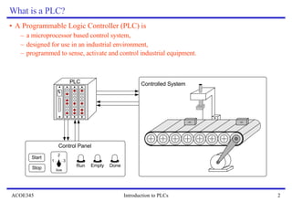
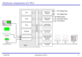
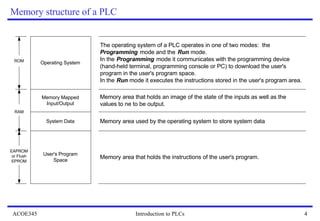

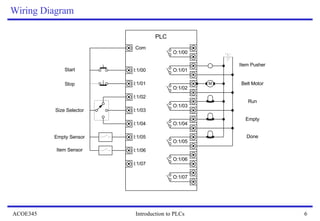

A Programmable Logic Controller (PLC) is a microprocessor-based control system used in industrial environments to sense, activate, and control equipment. PLCs operate in one of two modes: program mode, where a user's program is downloaded to the PLC memory, and run mode, where the program executes in a continuous scan-based cycle of reading inputs, executing the program, and updating outputs. PLCs use digital and analog inputs and outputs to interface with sensors and actuators in industrial control applications.


