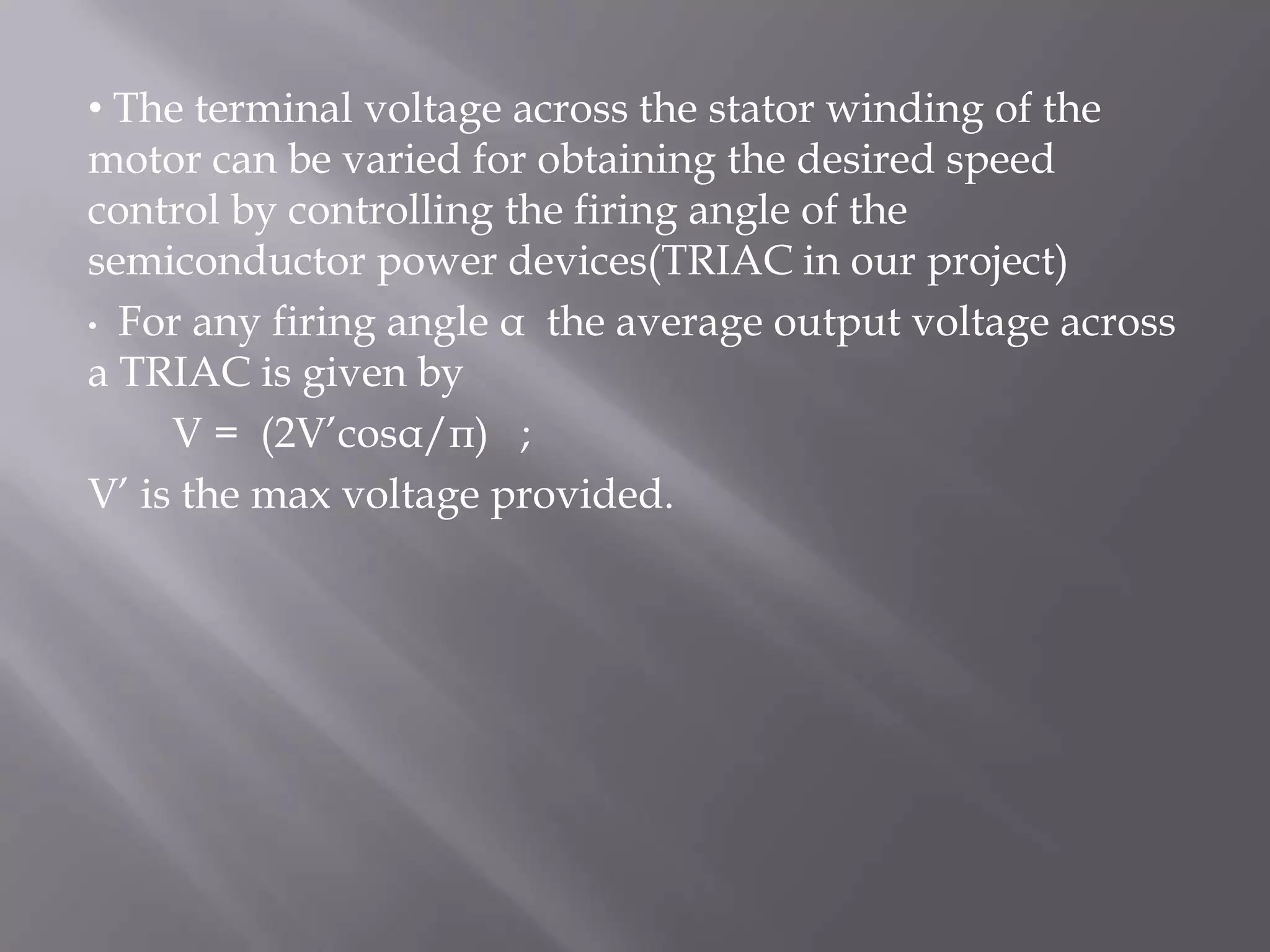
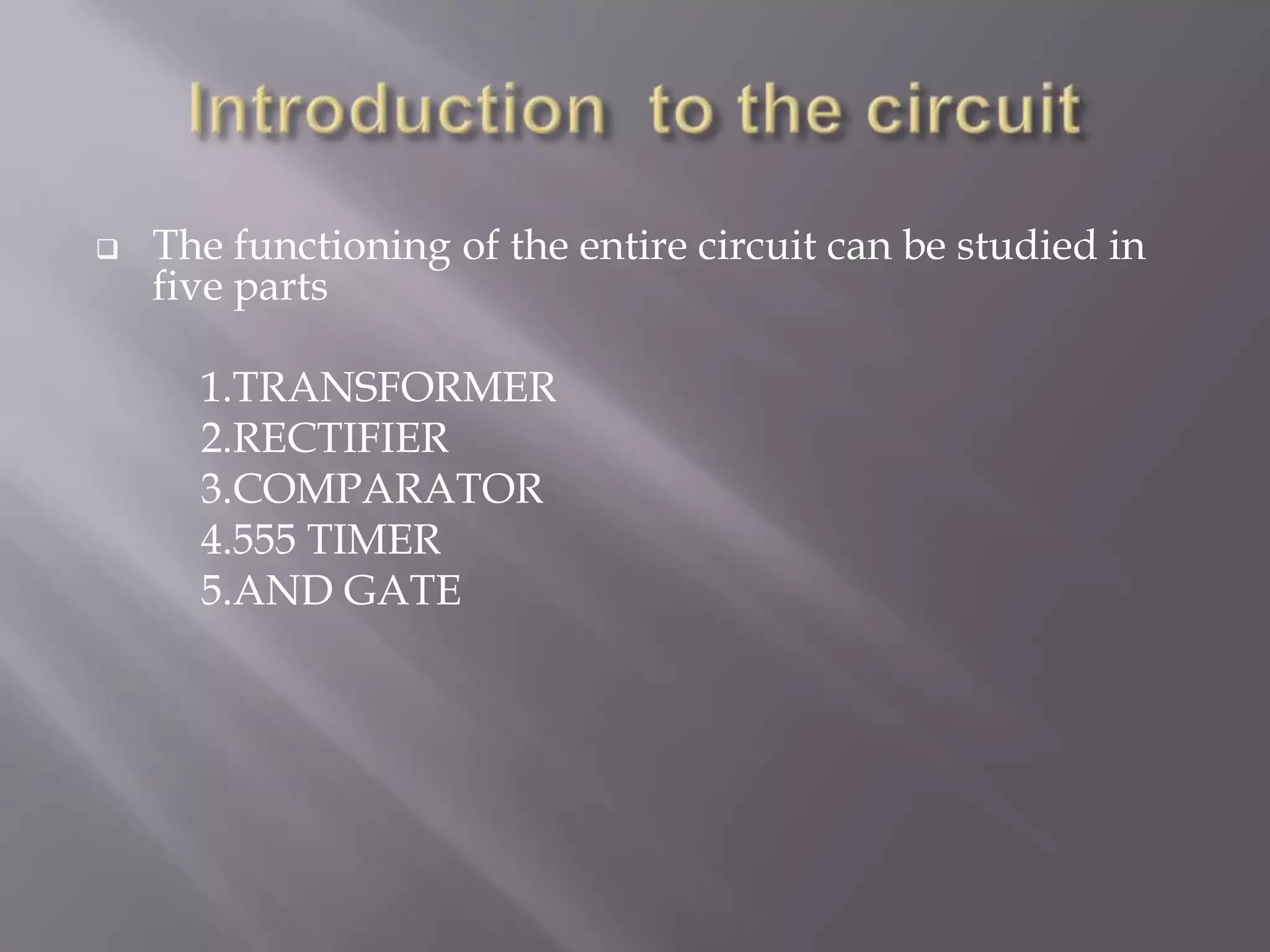
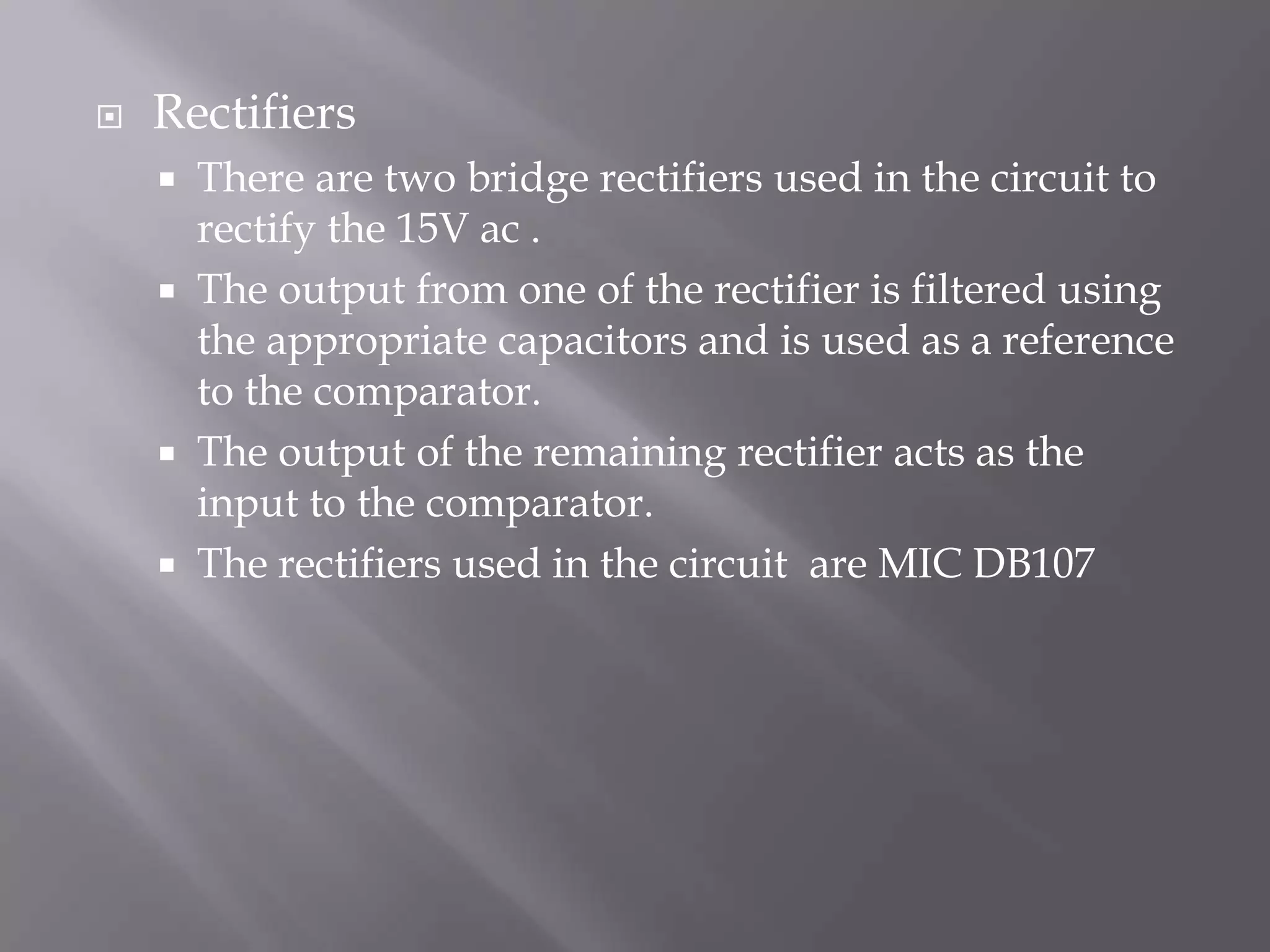
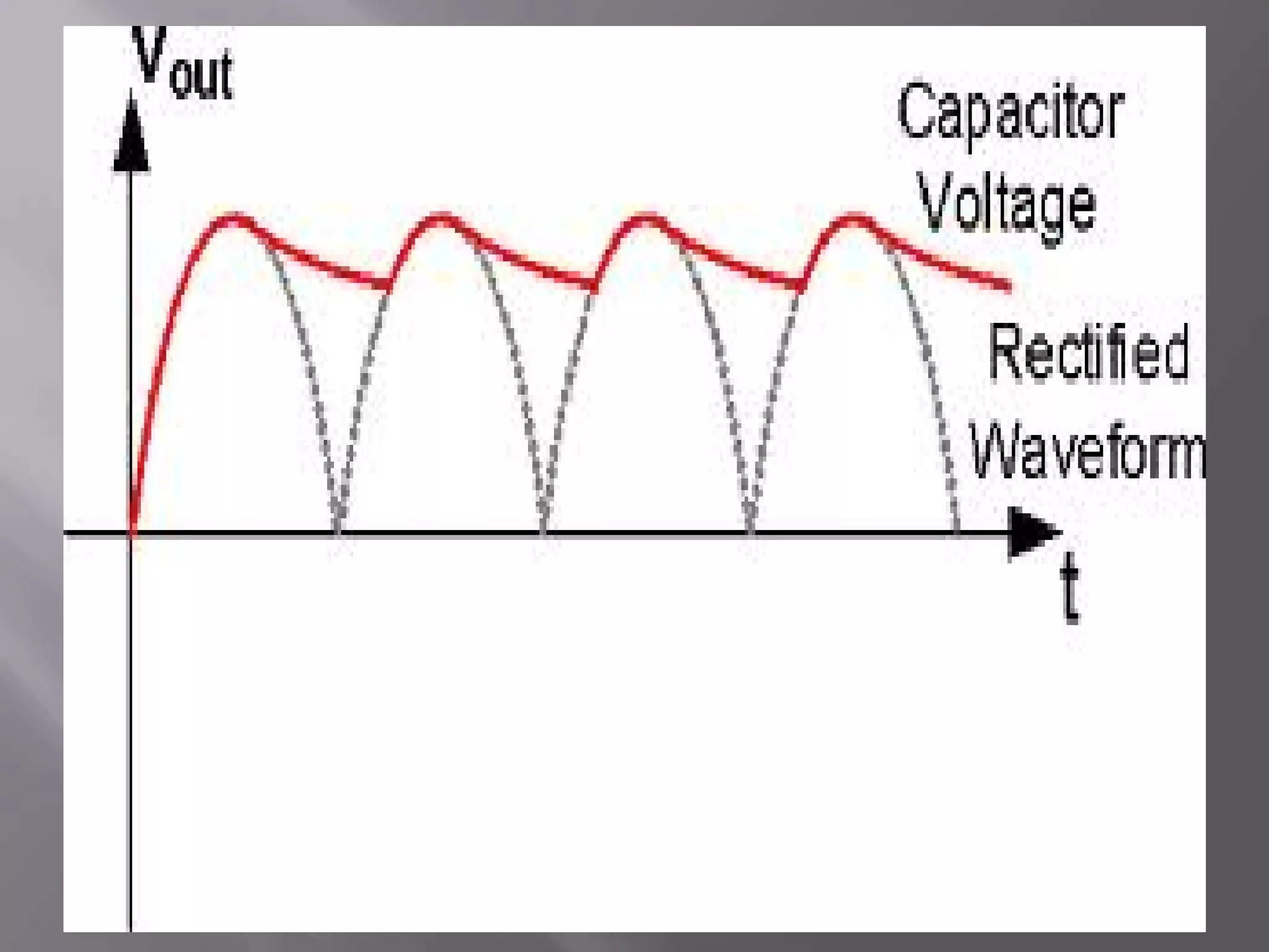
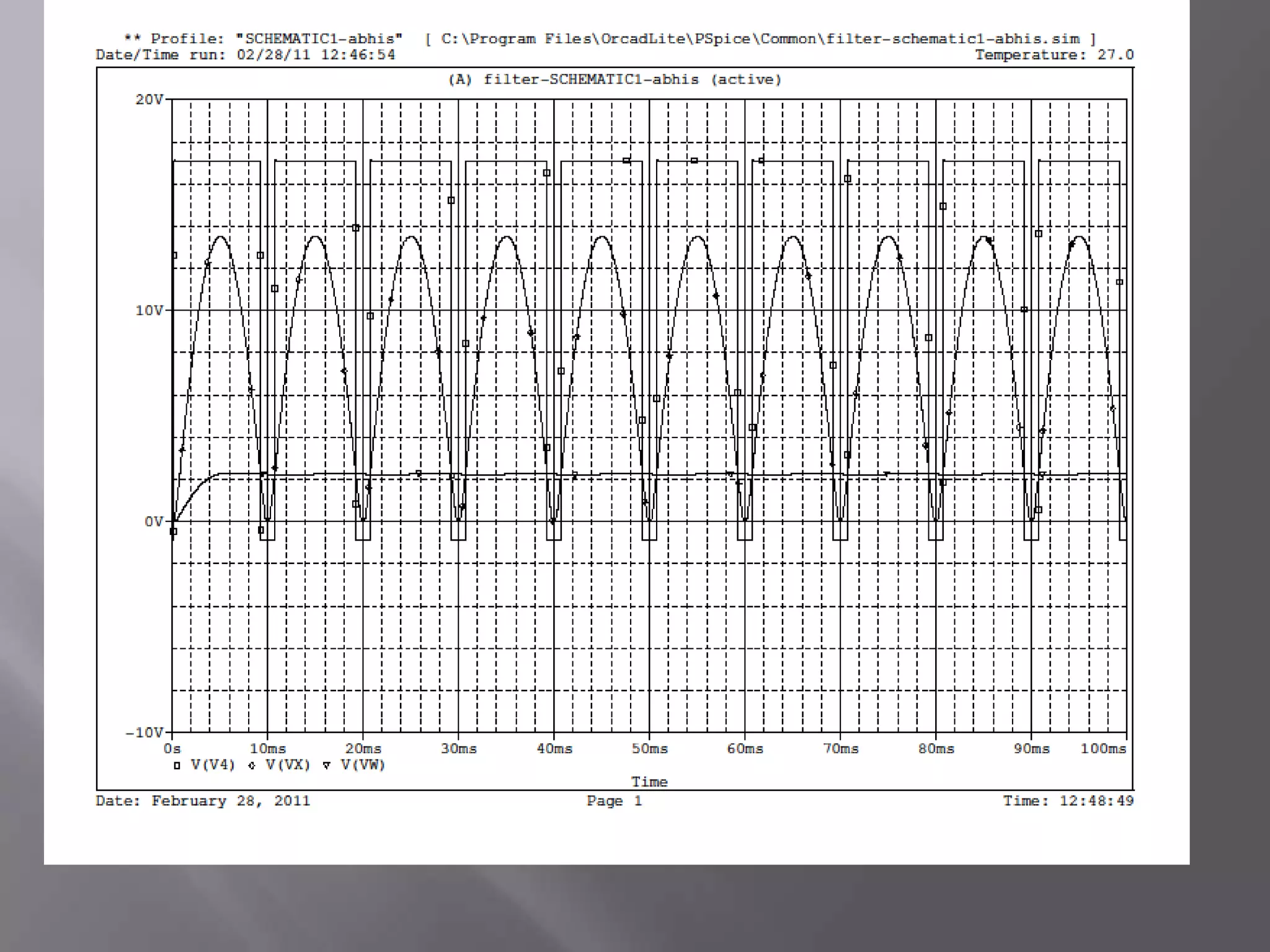
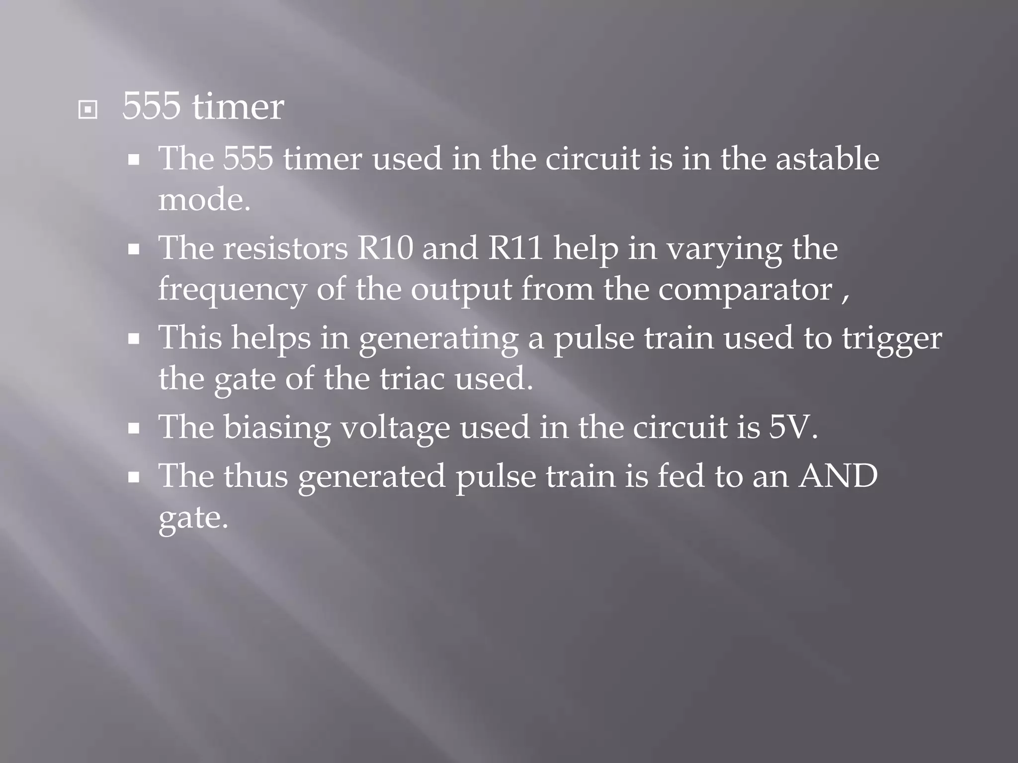
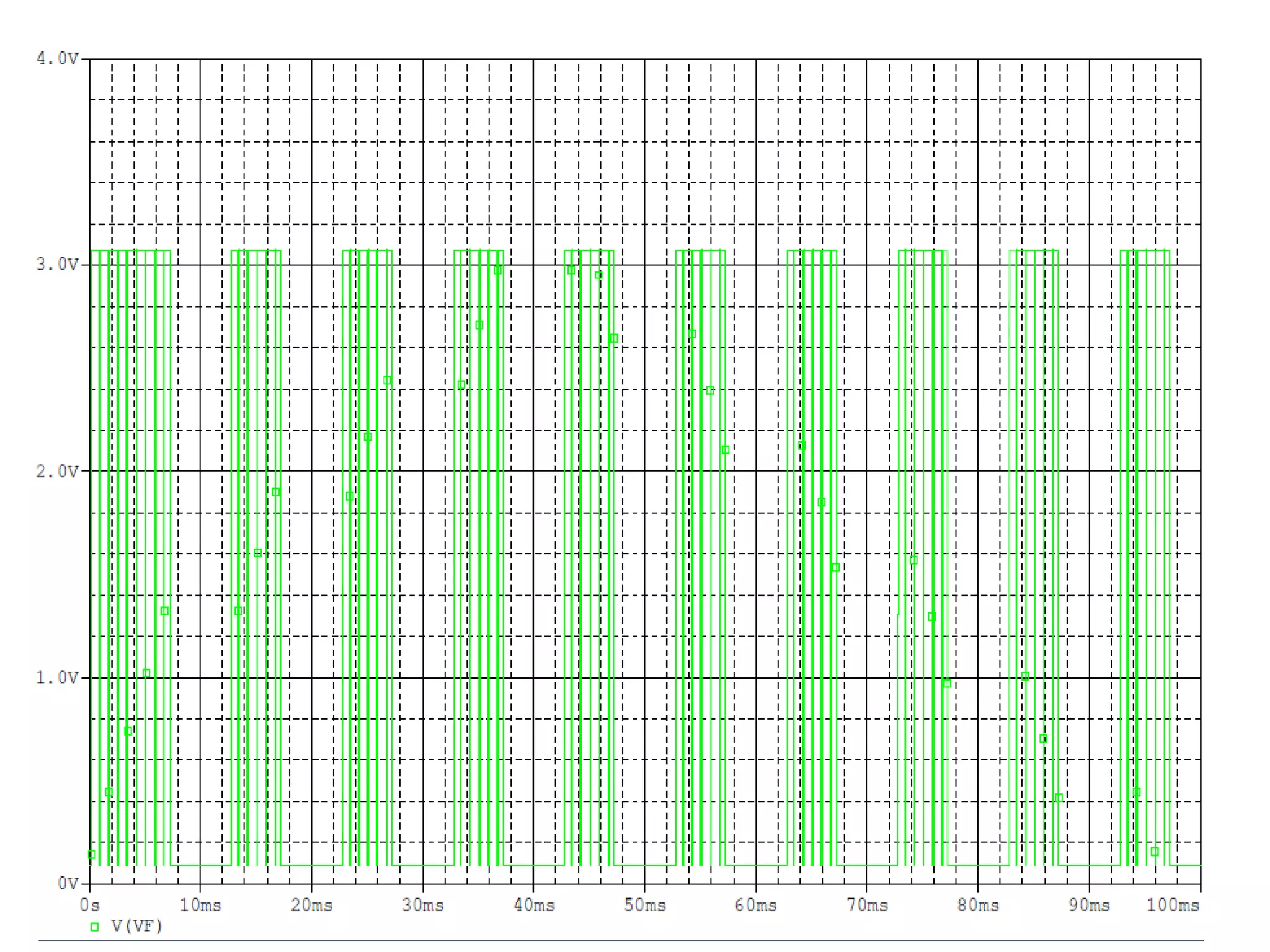
SPEED CONTROL OF 1-φ INDUCTON MOTOR USING A TRIAC
SUBMITTED BY: GROUP NO: 14  ABHISHEK SHIVHARE                     081113013  ASHWANI KUMAR AHIRWAR      081113042  MD JAWED HUSSAIN                       081113057  SUSHIL DAYMA                                 081113062  B.B.HARISH REDDY                          081113065
INTRODUCTION  Single phase induction motor are small motors having a wide field of usefulness where a poly phase supply is not available. They are generally used in fans, blowers, washing machines, refrigerators, etc.
The speed of the induction motor can be varied in a narrow range by varying the voltage applied to the stator winding.
 This method of speed control is suitable for such applications, where the load varies approximately as the square of speed, such as centrifugal pump drives, fan load.  The terminal voltage across the stator winding of the       motor can be varied for obtaining the desired speed control by controlling the firing angle of the  semiconductor power devices(TRIAC in our project)
  For any firing angle α  the average output voltage across a TRIAC is given by        V =  (2V’cosα/π)   ;  V’ is the max voltage provided.
Instruments used
Introduction  to the circuitThe functioning of the entire circuit can be studied in five parts               1.TRANSFORMER          2.RECTIFIER          3.COMPARATOR          4.555 TIMER          5.AND GATE
TRANSFORMER The transformer in our circuit is a step down transformerThis  transforms the 220V input to 15V at 1 amp.It acts as an isolation device between the ac mains and the electronic circuit.
RectifiersThere are two bridge rectifiers used in the circuit to rectify the 15V ac .The output from one of the rectifier is filtered using the appropriate capacitors and is used as a reference to the comparator.The output of the remaining rectifier acts as the input to the comparator.The rectifiers used in the circuit are MIC DB107
ComparatorThe comparator used in the circuit is LM324The comparator compares the rectified voltage at the positive terminal with the filtered input voltage at the negative terminal which acts as a reference and hence generates a square wave.The magnitude of the square wave is equal to the saturation value, and its magnitude is positive when the input voltage is greater than the reference voltage and vice versa.The resultant output wave forms the input to the AND gate
PIN DIAGRAM OF LM324
INTERNAL DIAGRAM OF LM324
555 timer The 555 timer used in the circuit is in the astable mode.The resistors R10 and R11 help in varying the frequency of the output from the comparator ,This helps in generating a pulse train used to trigger the gate of the triac used.The biasing voltage used in the circuit is 5V.The thus generated pulse train is fed to an AND gate.
AND gateThe AND gate used in the circuit is HD74S08.The input of the gate is derived from the output of the comparator and of the 555 timer.The AND gate is used to eliminate the negative pulse train.

Speed control of 1 φ inducton motor using traic

  • 1.
    SPEED CONTROL OF1-φ INDUCTON MOTOR USING A TRIAC
  • 2.
    SUBMITTED BY: GROUPNO: 14 ABHISHEK SHIVHARE 081113013 ASHWANI KUMAR AHIRWAR 081113042 MD JAWED HUSSAIN 081113057 SUSHIL DAYMA 081113062 B.B.HARISH REDDY 081113065
  • 3.
    INTRODUCTION Singlephase induction motor are small motors having a wide field of usefulness where a poly phase supply is not available. They are generally used in fans, blowers, washing machines, refrigerators, etc.
  • 4.
    The speed ofthe induction motor can be varied in a narrow range by varying the voltage applied to the stator winding.
  • 5.
    This methodof speed control is suitable for such applications, where the load varies approximately as the square of speed, such as centrifugal pump drives, fan load. The terminal voltage across the stator winding of the motor can be varied for obtaining the desired speed control by controlling the firing angle of the semiconductor power devices(TRIAC in our project)
  • 6.
    Forany firing angle α the average output voltage across a TRIAC is given by V = (2V’cosα/π) ; V’ is the max voltage provided.
  • 7.
  • 9.
    Introduction tothe circuitThe functioning of the entire circuit can be studied in five parts 1.TRANSFORMER 2.RECTIFIER 3.COMPARATOR 4.555 TIMER 5.AND GATE
  • 10.
    TRANSFORMER The transformerin our circuit is a step down transformerThis transforms the 220V input to 15V at 1 amp.It acts as an isolation device between the ac mains and the electronic circuit.
  • 11.
    RectifiersThere are twobridge rectifiers used in the circuit to rectify the 15V ac .The output from one of the rectifier is filtered using the appropriate capacitors and is used as a reference to the comparator.The output of the remaining rectifier acts as the input to the comparator.The rectifiers used in the circuit are MIC DB107
  • 13.
    ComparatorThe comparator usedin the circuit is LM324The comparator compares the rectified voltage at the positive terminal with the filtered input voltage at the negative terminal which acts as a reference and hence generates a square wave.The magnitude of the square wave is equal to the saturation value, and its magnitude is positive when the input voltage is greater than the reference voltage and vice versa.The resultant output wave forms the input to the AND gate
  • 14.
  • 15.
  • 18.
    555 timer The555 timer used in the circuit is in the astable mode.The resistors R10 and R11 help in varying the frequency of the output from the comparator ,This helps in generating a pulse train used to trigger the gate of the triac used.The biasing voltage used in the circuit is 5V.The thus generated pulse train is fed to an AND gate.
  • 19.
    AND gateThe ANDgate used in the circuit is HD74S08.The input of the gate is derived from the output of the comparator and of the 555 timer.The AND gate is used to eliminate the negative pulse train.
  • 21.
    PROGRESS MADE SOFARP SPICE simulation has been completed
  • 22.
    Bread board testinghas been done
  • 23.
    Working on PCB THANK YOU