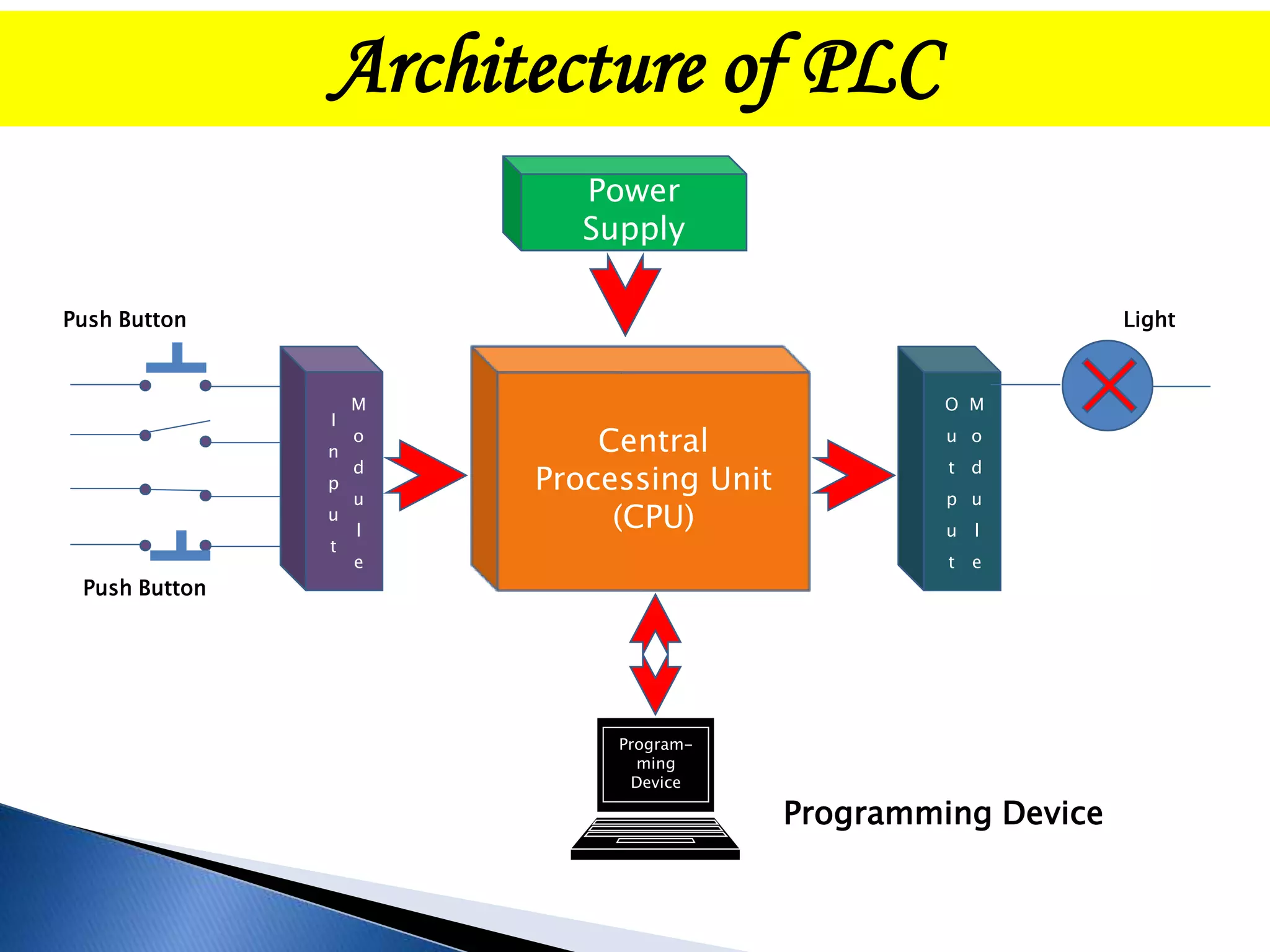
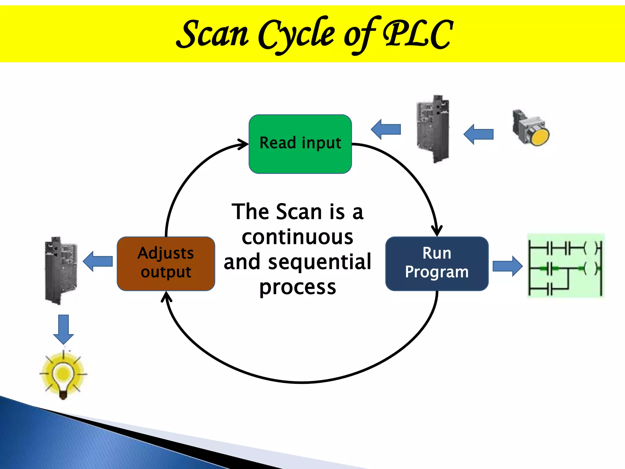
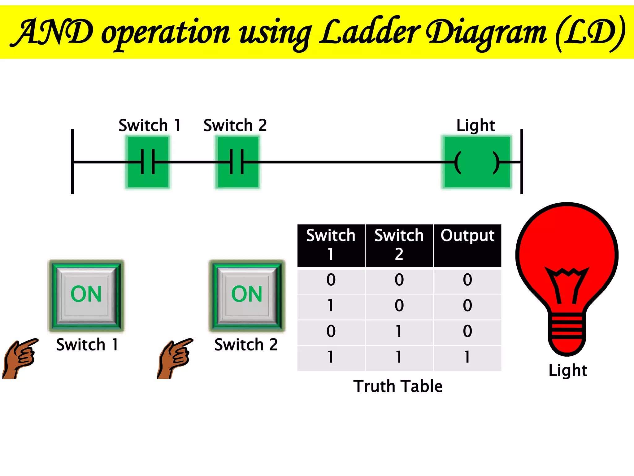
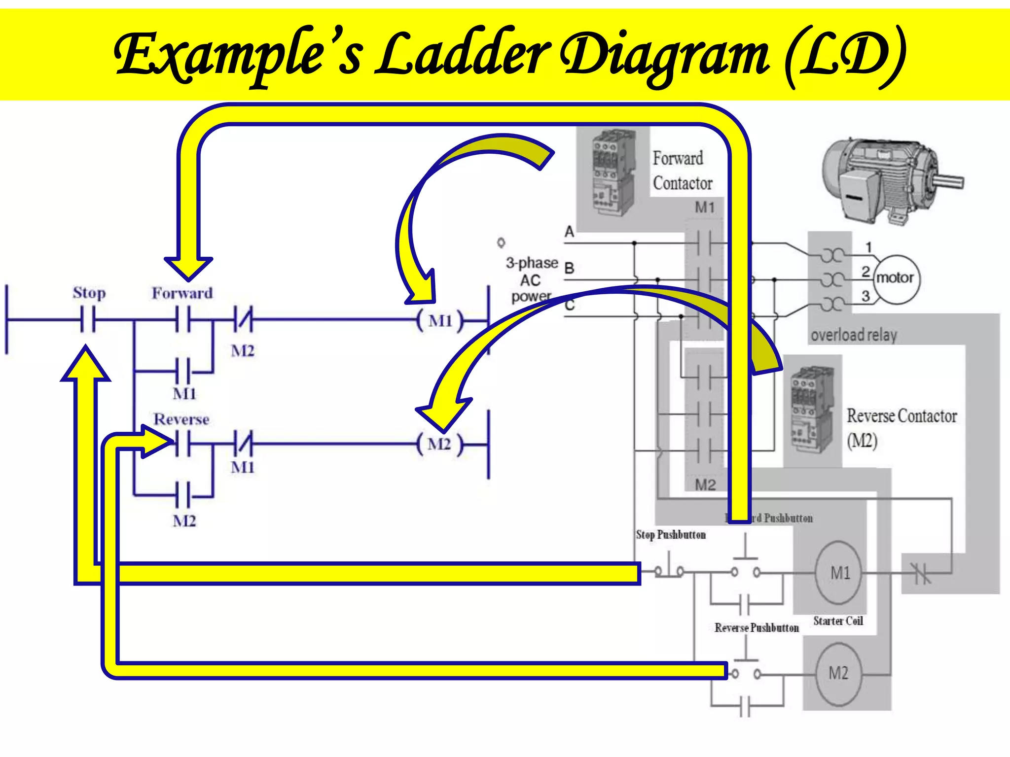
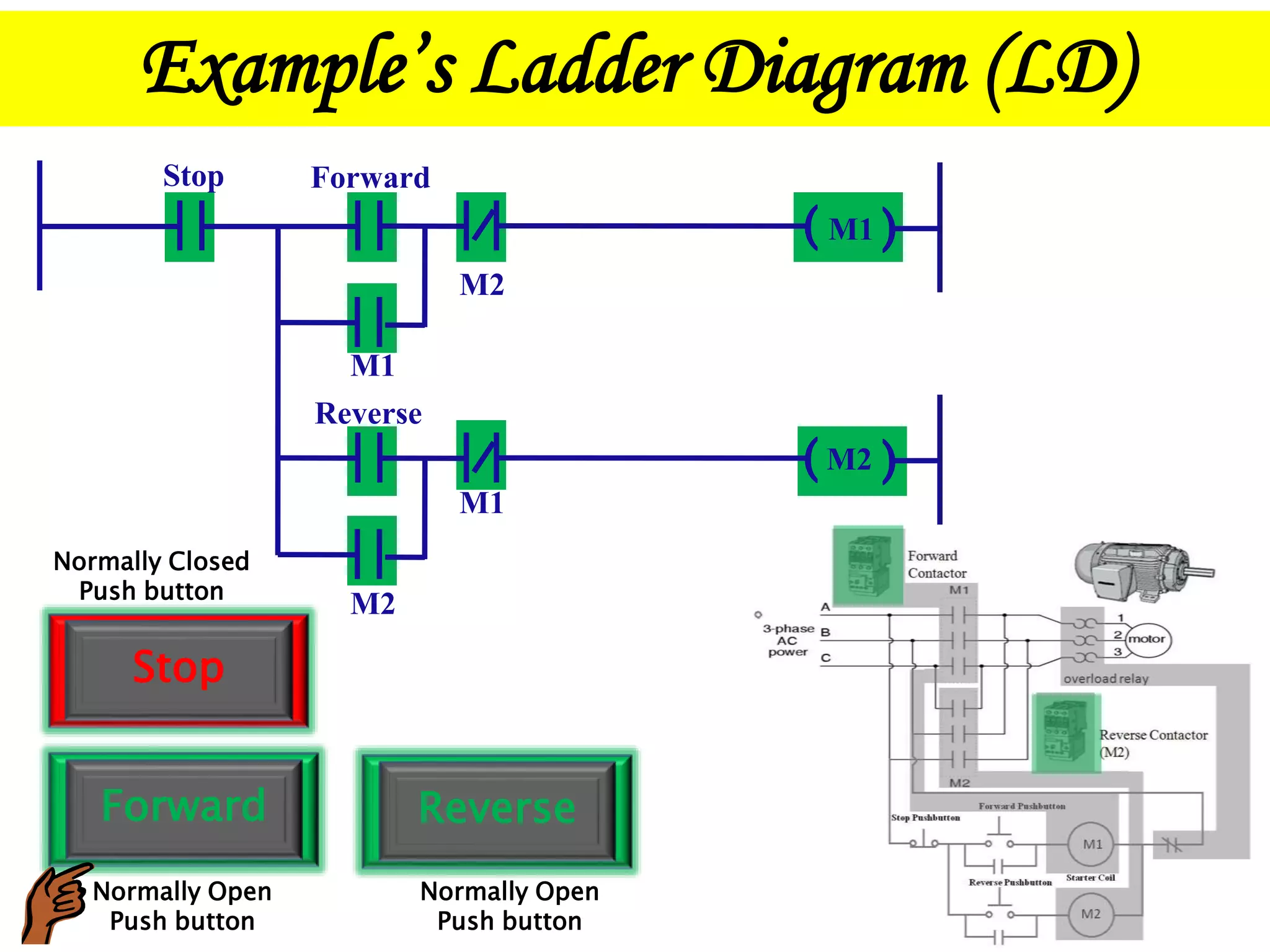
The document provides information about programmable logic controllers (PLCs). It defines a PLC as a digital computer used to automate electromechanical processes. The document then discusses the key advantages of PLCs like being cost-effective, flexible, and able to operate reliably for years. It also describes the basic architecture of a PLC including input and output modules, a central processing unit, and a programming device. Examples of ladder logic programming are also included to illustrate how PLCs can be programmed to control processes like starting motors in forward and reverse directions.
2. What Is Programmable Logic Controller?
A programmable Logic Controller (PLC) is a digital
computer used for automation of electromechanical
processes, such as control of machinery on factory
assembly lines, amusement rides, or light fixtures.
3. • Cost effective for controlling complex systems.
• Flexible and can be reapplied to control other systems
quickly and easily.
• Computational abilities allow more sophisticated control.
• Trouble shooting aids make programming easier and reduce
downtime.
• Reliable components make these likely to operate for years
before failure.
• Small physical size, so shorter project time.
•Ease in documentation.
Advantages of PLC
5. Architecture of PLC
Input Module : It senses the presence or absences of an input signal at each of its
input terminal.
Output Module : The output module operates the opposite manner from the input
signal. A DC signal from the CPU is converted through each module section to a
usable output voltage.
Central Processing Unit (CPU) : It is the brain of every computer. CPU carries out
arithmetic and logical operations.
Programming Device : A programming device is a computer in which programming
is done and then by using data cables the program is downloaded into the PLC. For
connecting to the PLC “RC-232C” cable is used.
RS-232C Cable
6. Scan Cycle of PLC
Read input
Run
Program
Adjusts
output
The Scan is a
continuous
and sequential
process
7. • There are three types of PLC.
1. Unitary PLC
Types Of PLC
2. Modular PLC
3. Rack Mounted PLC :
8. It contains every feature of a basic system in one box.
They are attached to the machine being controlled.
Advantages:
1. Less scanning time
2. Fixed versions are usually small, have less memory so
cost in less .
3. Less troubleshooting time so less downtime.
Disadvantages :
1. A limited number of inputs and outputs.
2. It is not suited for future expansion.
3. If part of the unit fails, it will take much time and
effort to repair, and the entire unit may need replacing.
Unitary PLC
9. It s a range of modules that slot together to build up a system.
The basic are the power supply, the main module containing the
CPU, the input and output module.
Advantages:
1. Great flexibility in choice of modules. Modules can be easily
installed or removed without affecting other modules
2. The main advantage is that more Input and output terminals can
be expanded.
Disadvantages :
1. Scanning time increases with the increase in input and output
modules.
Modular PLC
10. This is similar concept to the modular design but the modules
are on standard cards that slot into a standard rack inside a
cabinet. These are flexible and allow expansion of the system.
Rack Mounted PLC
11. What happens when line voltage comes in contact with
the low voltage DC section of PLC?
6
5 4
3
2
18
7
Relay Coil
NO
NC
NO
NC
24 V
230 V
Plug in base of relay
PLC
12. What happens when line voltage comes in contact with
the low voltage DC section of PLC?
6
5 4
3
2
18
7
Relay Coil
NO
NC
NO
NC
24 V
230 V
Plug in base of Relay
PLC
13. Optical Isolation
It means there is no actual electrical
connection between the input device and the
processor. This eliminates any possibility of the
input line voltage from coming in contact with and
damaging the low voltage DC section of the
processor. It prevents any unwanted voltage from
the i/o section of the processor.
15. Programming Languages of PLC
There are “5” programming Languages in PLC
1. Ladder Diagram (LD)
2. Functional Block Diagram (FBD)
3. Structured Text (ST)
4. Instruction List (IL)
5. Sequential Function Chart (SFC)
16. Ladder Diagram (LD)
It is a graphical programming language. It is programmed
with simple contacts that simulated the opening and
closing of relays it has been expanded to include function
such as counters, timers, shift registers and math
operation.
17. Ladder Diagram (LD)
Contacts and coils
Examine if closed
Examine if open
It works as normally open switch in a ladder program. If it is ON,
the contact will close and allow power (logic) to flow from left to
right. If the status is OFF (logical 0), the contact is Open, power
(logic) will NOT flow from left to right.
It works as normally closed switch in a ladder program, and it
works exactly opposite to that of the examine if closed.
Normally open coil
This can be used to represent any discrete output from the control
logic. When "solved" if the logic to the left of the coil is TRUE, the
referenced output is ON (logical 1).
18. Ladder Diagram (LD)
Timer
•The Timer On Delay instruction begins to count time base intervals
when rung conditions become true. As long as rung conditions
remain true, the timer adjust its accumulated value (ACC) each
evaluation until it reaches the preset value (PRE). The accumulated
value is reset when rung conditions go false, regardless of whether
the timer has timed out.
Timer On Delay
Timer T4:1
Time Base 1.0
Preset 100
Accum 0
TON
(
(
(
(
EN
DN
19. Ladder Diagram (LD)
Counter
•Increments the accumulated value at each false to true transition
and retains the accumulated value when the instruction goes false or
when power cycle occurs.
•The CTU is an instruction that counts false to true transition.
When this transition happens the accumulated value is incremented
by one count.
•A CTU accumulation is reset by the RES instruction.
Count Up
Counter C3:0
Preset 10
Accum 0
CTU
(
(
(
(
CU
DN