Download to read offline


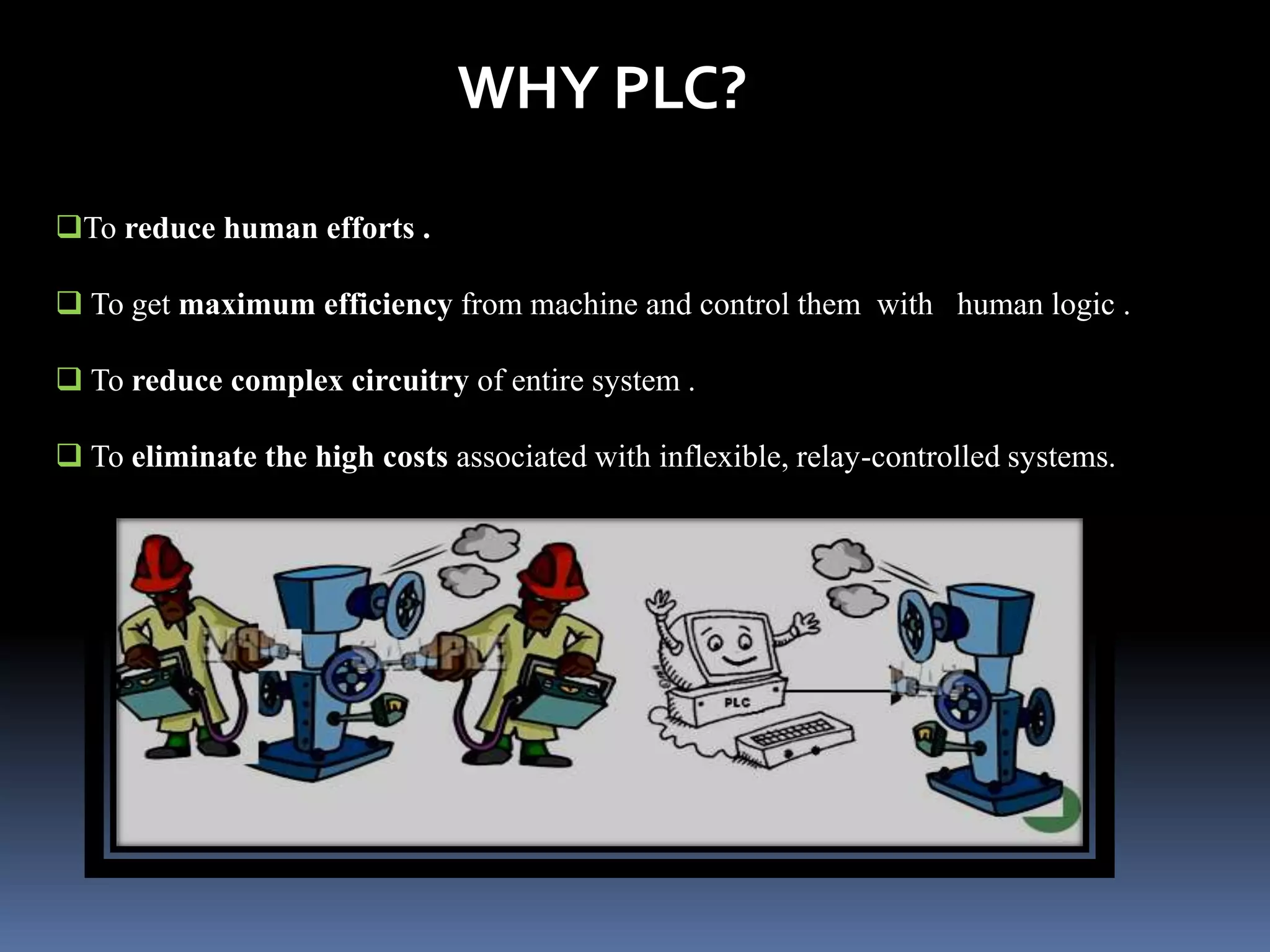

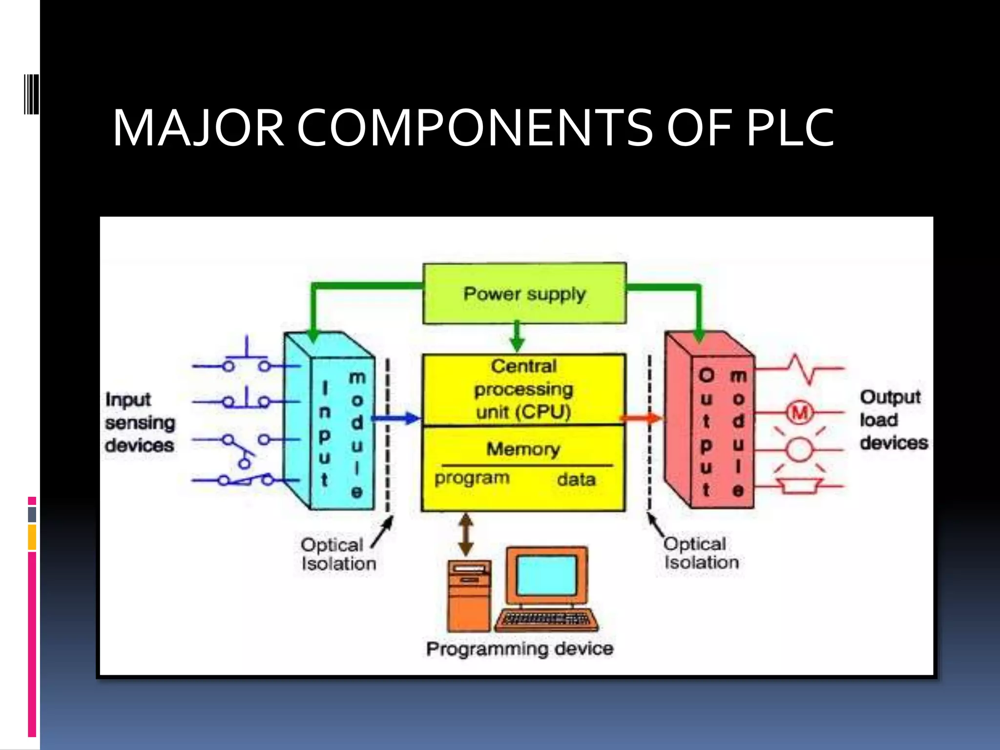
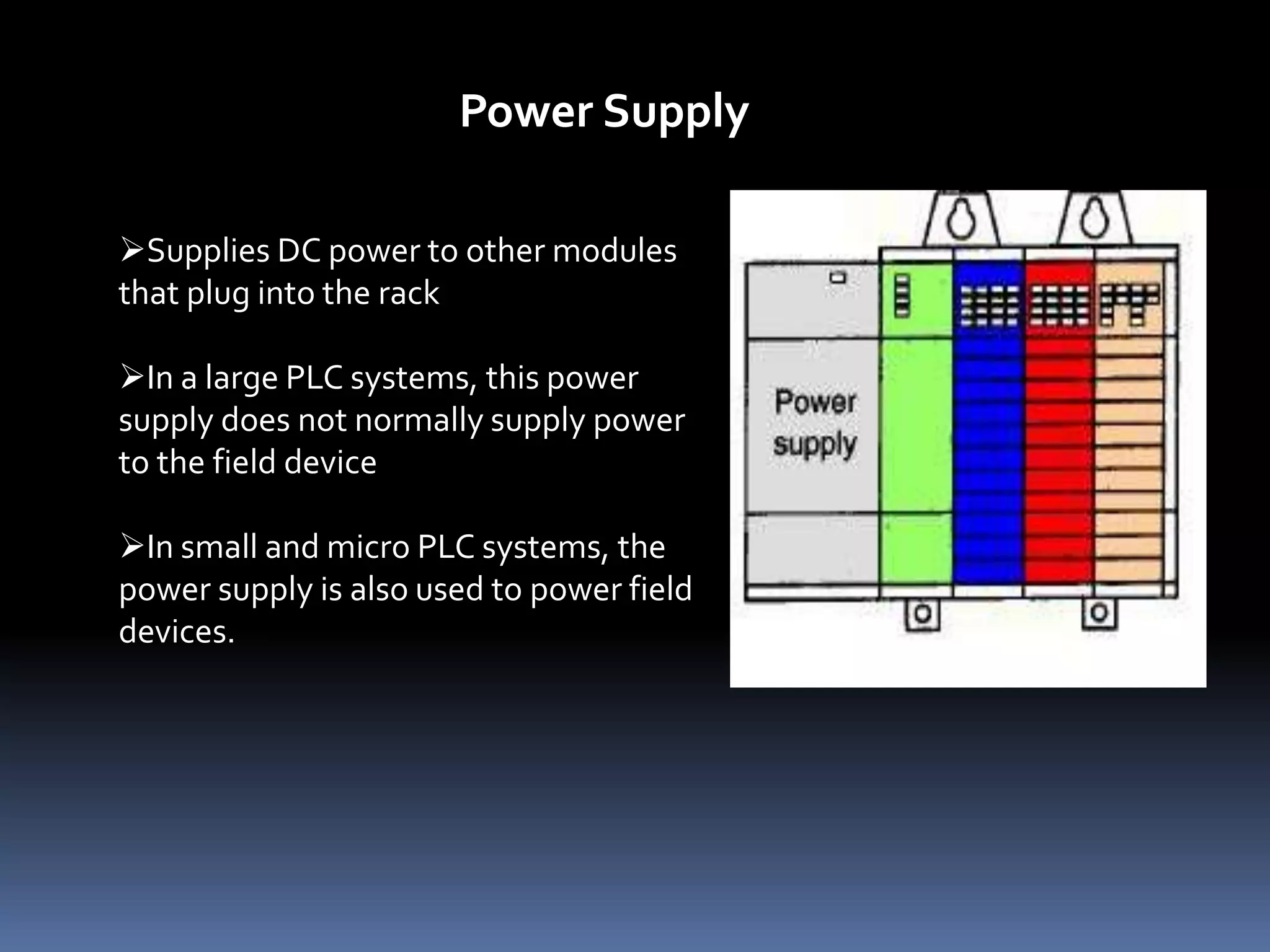


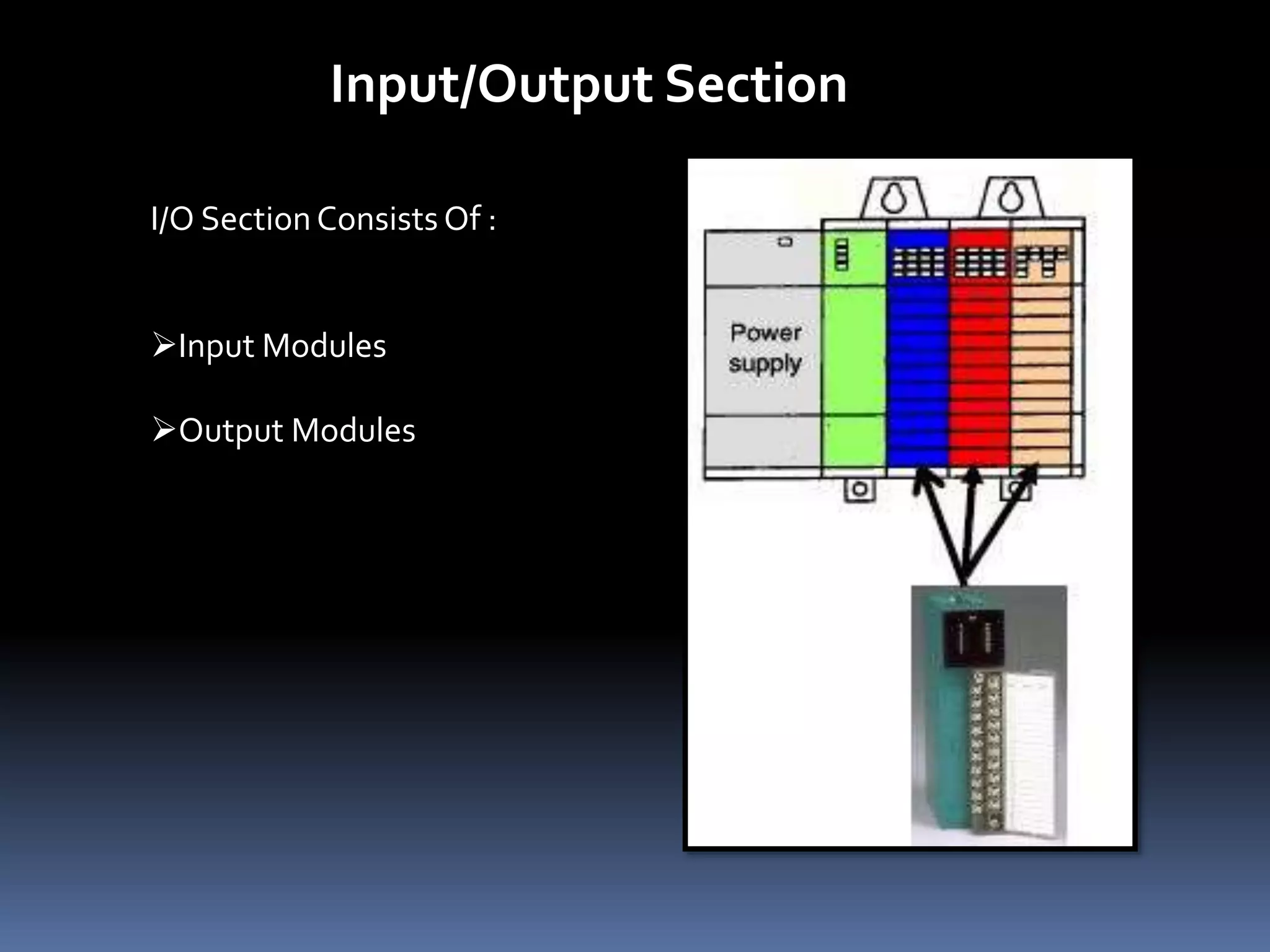


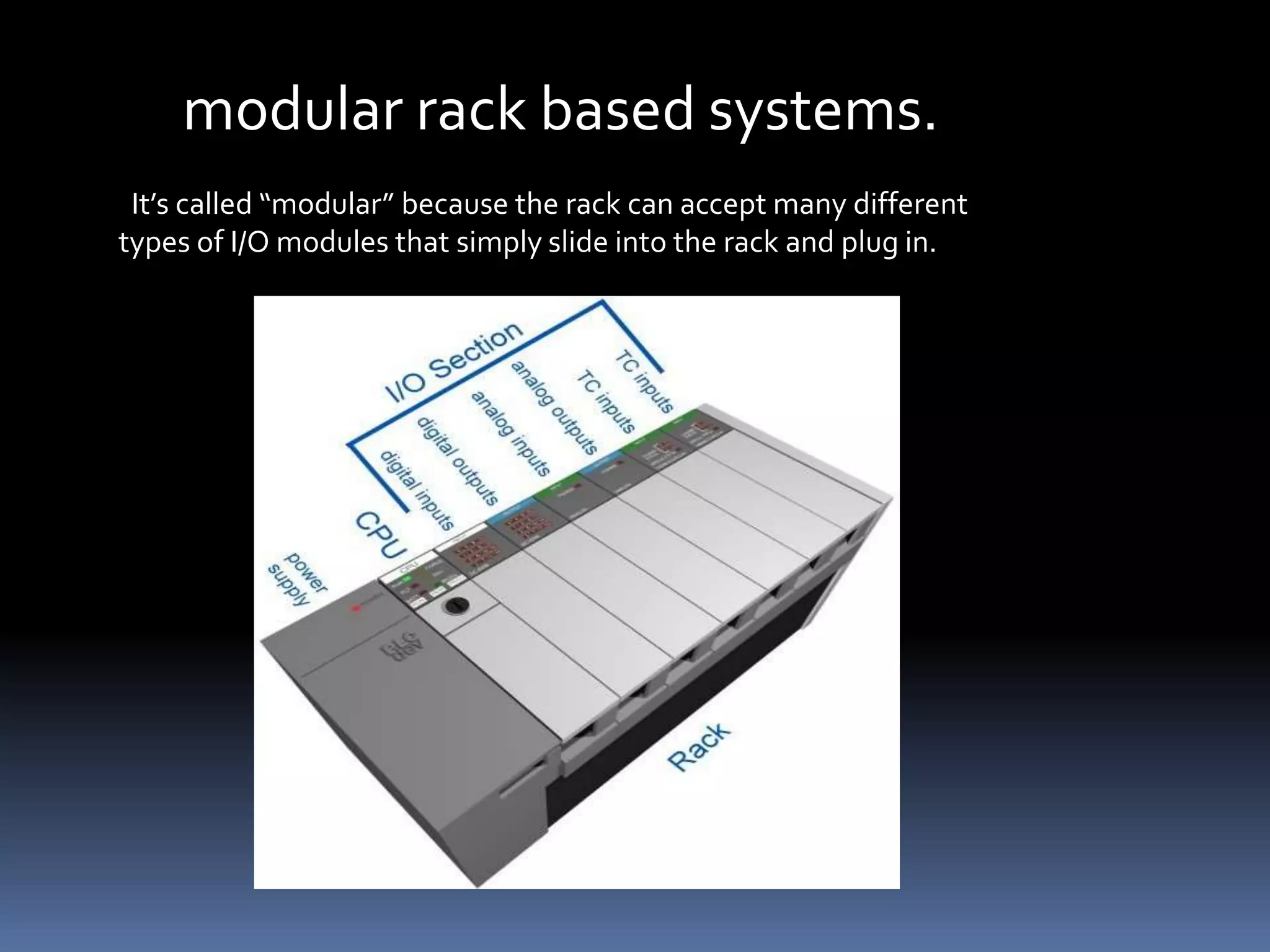

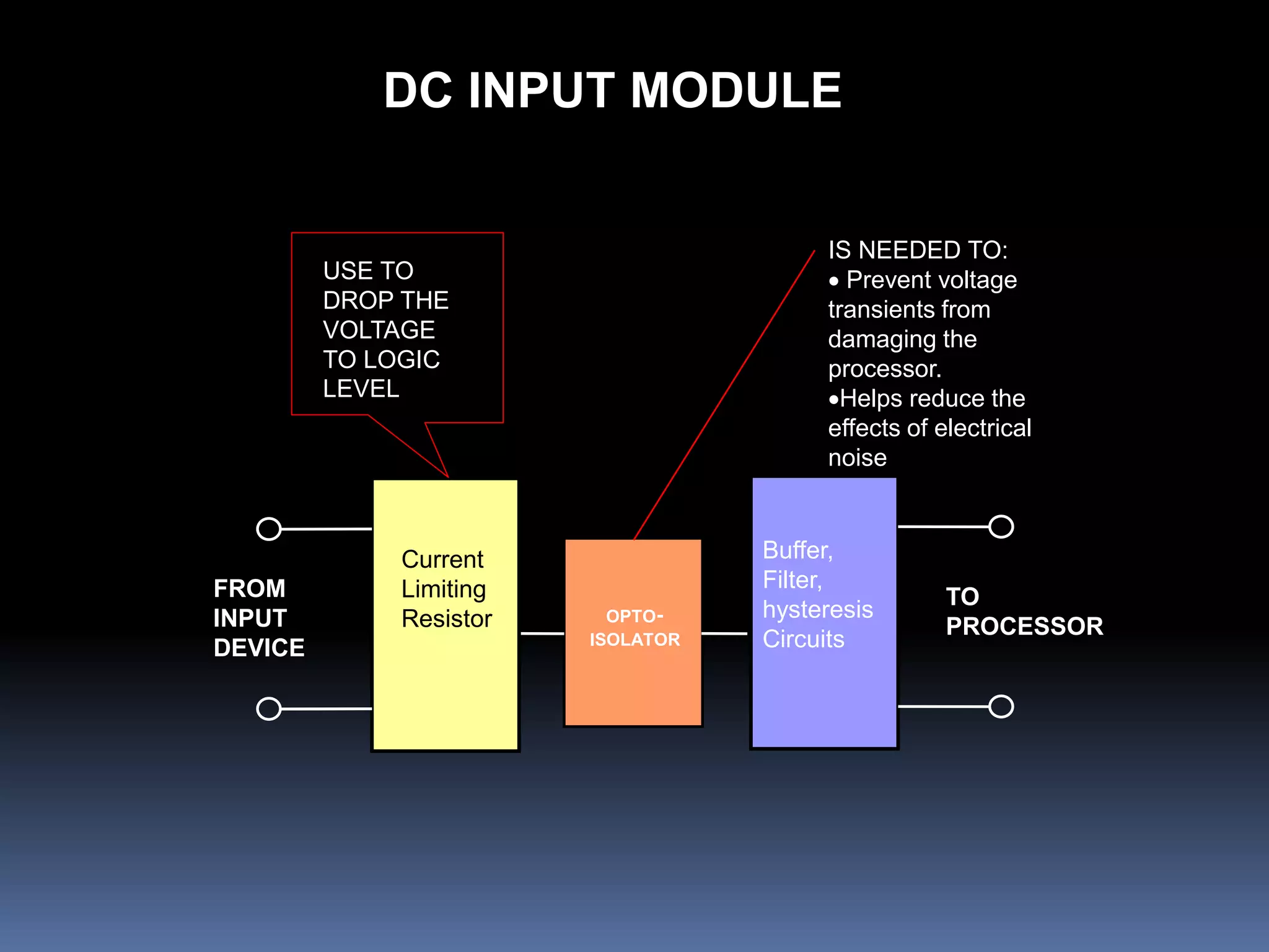
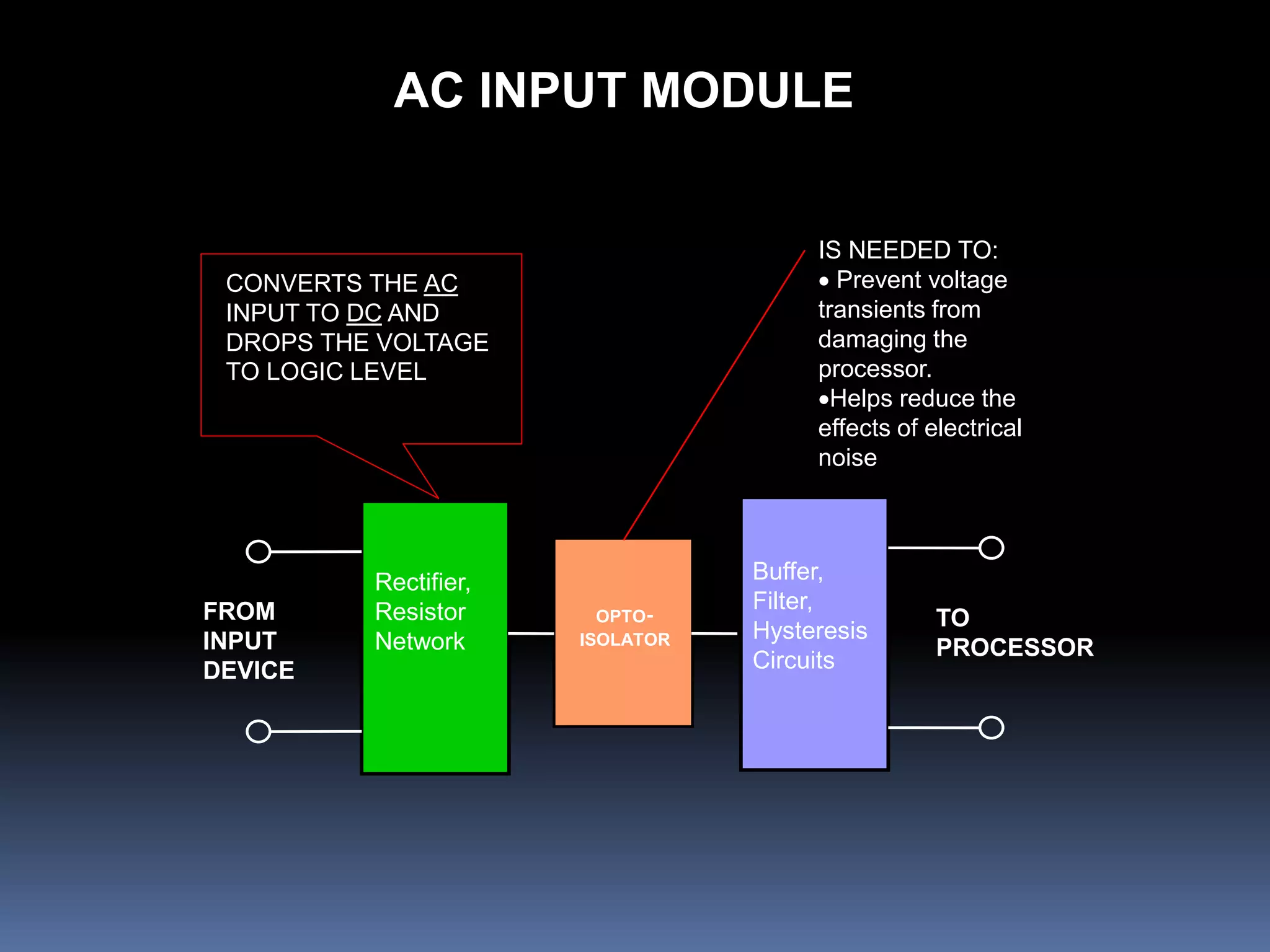


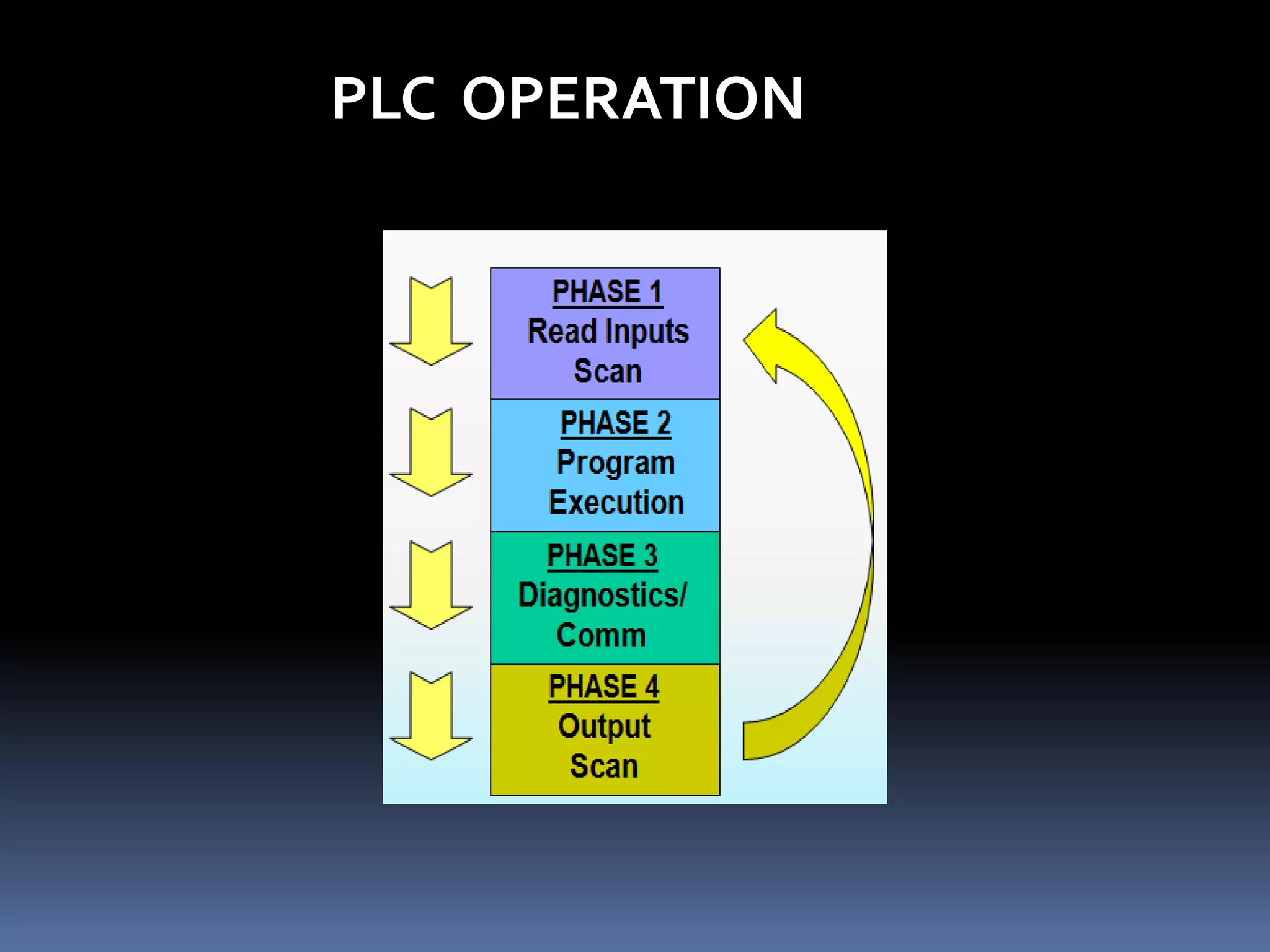

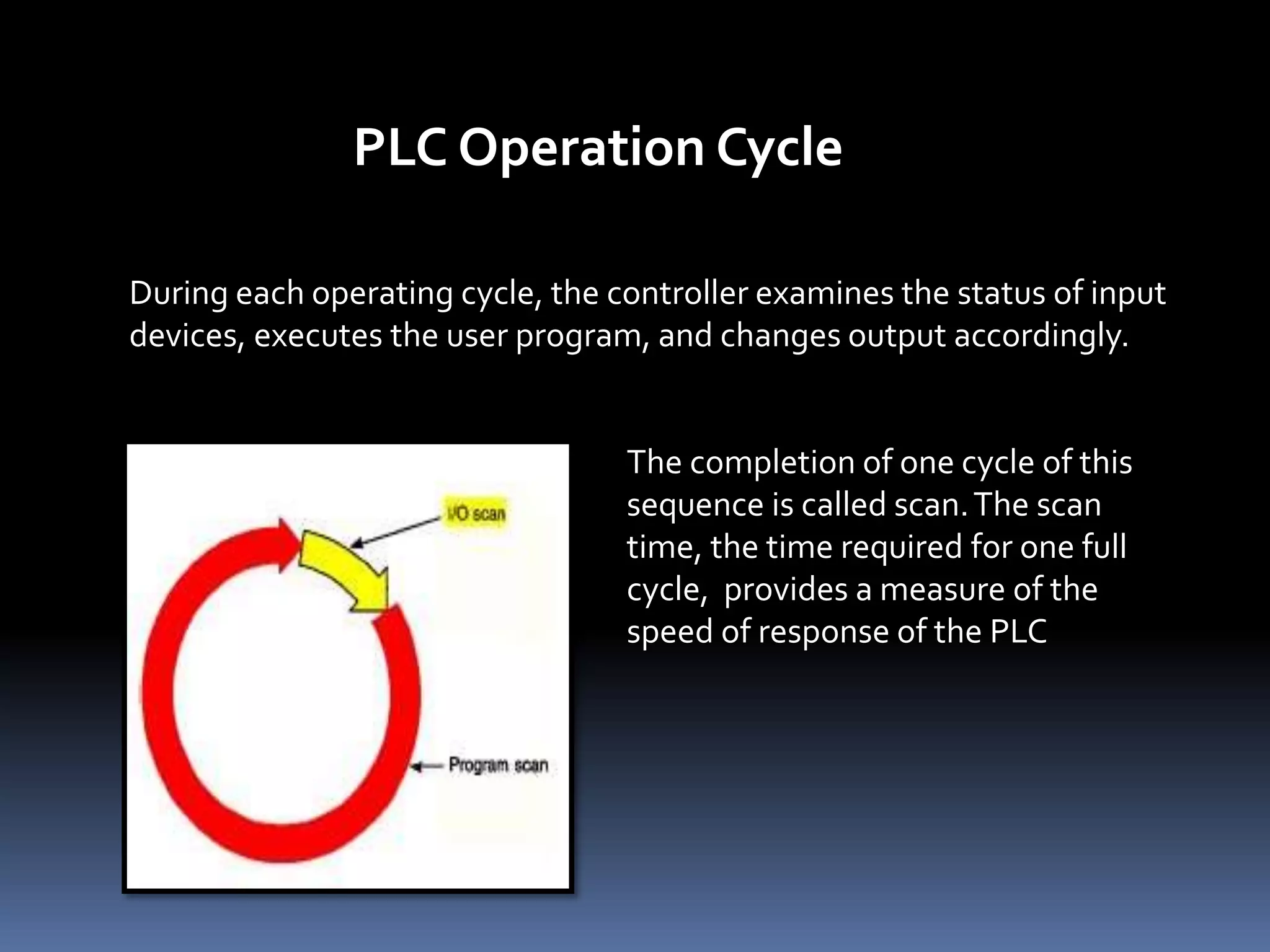
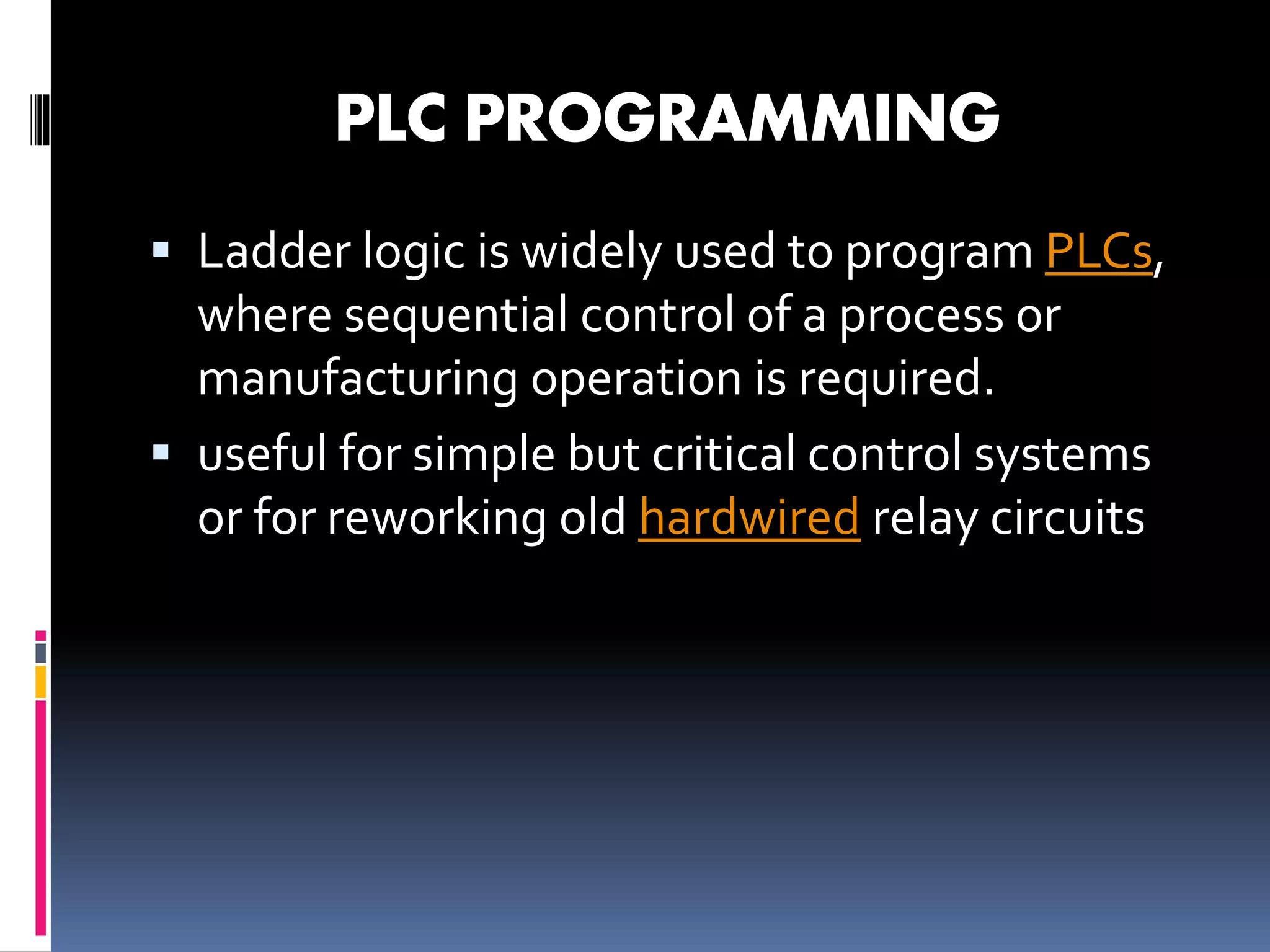


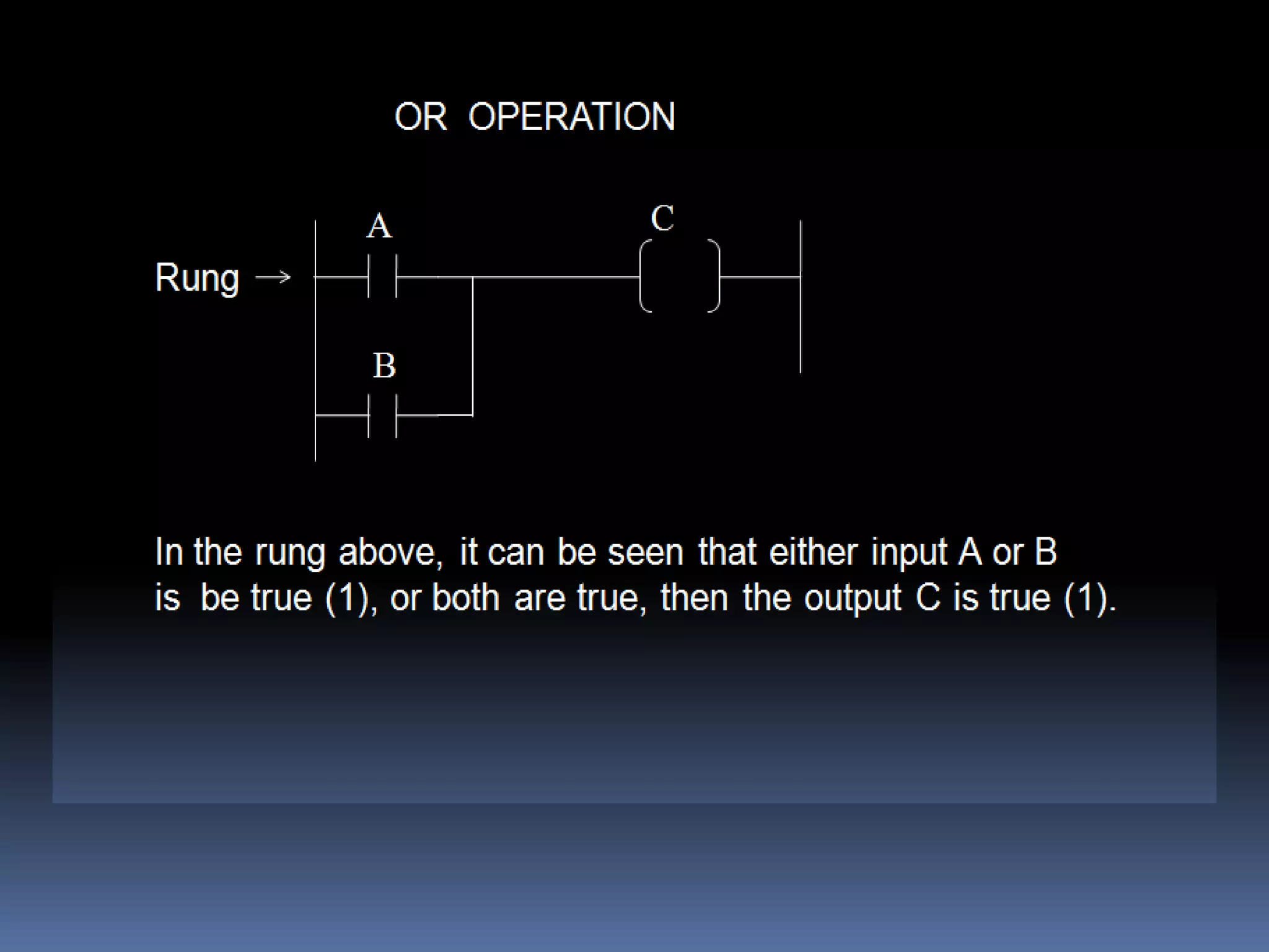
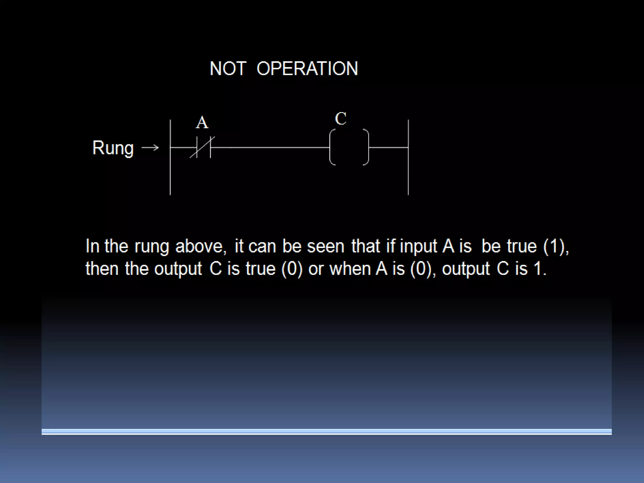
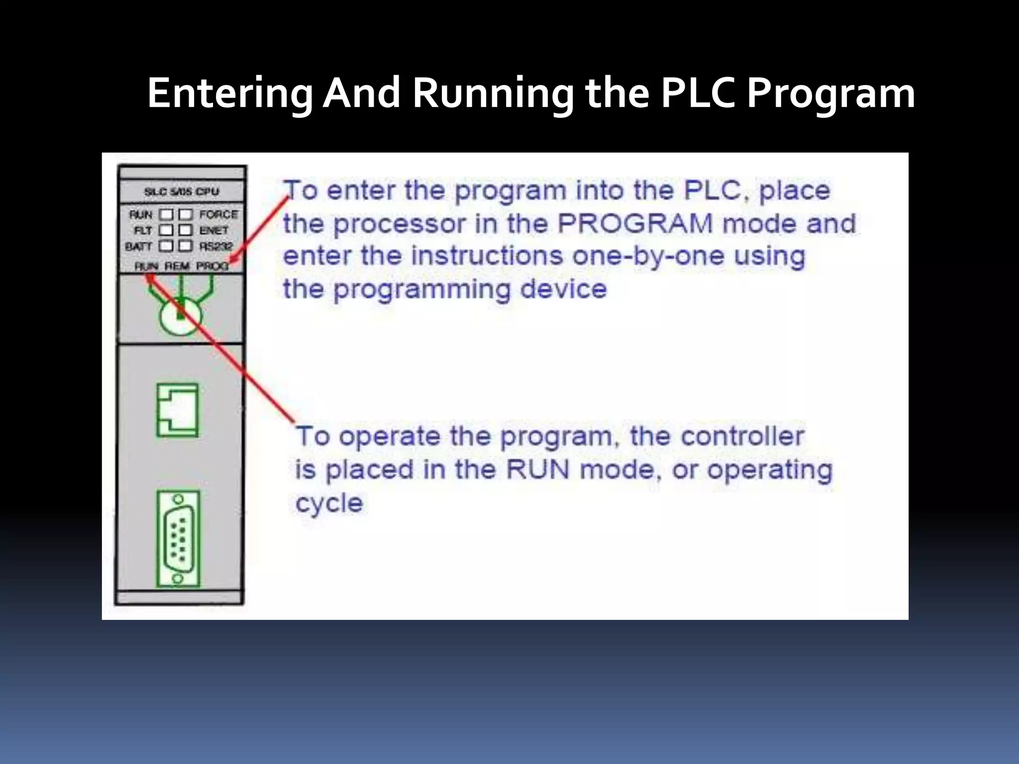


The document discusses automation and programmable logic controllers (PLCs). It describes how PLCs are used in industrial automation to control manufacturing processes and machines. The key components of a PLC system are described, including the central processing unit, memory, I/O modules, and power supply. The document outlines the basic operation of a PLC, including its scan cycle of reading inputs, executing a user program, and updating outputs. PLC programming using ladder logic is also discussed. Examples are provided of different types of inputs and outputs that can be connected to a PLC, as well as areas where PLCs are commonly applied.