SlideShare a Scribd company logo
History of PLC
Before the Programmable controller
• Control system implemented using relay controller.
• Lack of flexibilty for process changes or expansion
• Troubleshooting: Five hours to find and five minutes to fix,it.
History of PLC
• Before The days of the PLC The only way to control mahinery was
through the use of relays.
• PLC was Introduction in late 1960's
• First Commorercial and successful programmable logic controllers
was designed and devloped by modicon as a relay replacer for
general motors.
• Earlier it was a machine with thousands of electronic
parts.
What is a PLC ?
Why PLC Use ?
PLC
OUTPUT
PUSH
BUTTON
INPUT
Motor
A PLC is a solid state/Computerized industrial computer that
performs discrete( 0 , 1 ) or sequential logic in a factory
environment its called PLC
PLC:- Programmable Logic control
What Is PLC..
What is Sequential:- it means when you press a switch
then start light one by one.
What is Discrete:- It means when you press a switch then
start all light.
It was originally developed to replace mechanical
relay,Timer,Counters.PLC are used successfully to
execute complicated control operations in a plant.
Application
Process Automation Plants (e.g. mining, oil &gas)
Application
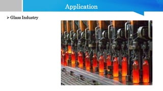
Glass Industry
Application
 Paper Industry
Application
 Cement Manufacturing
Application
 In boilers – Thermal Power Plants
 Car Manufacturing Plants..
Advantages
 Reliability
 Flexibility in programming and reprogramming
 Cost effective for controlling complex systems.
 Small Physical size, shorter project time.
 High Speed of operation.
 Ability to communicate With computer systems in the plant.
 Ease of maintenance / troubleshooting.
 Reduced space.
 Energy Saving
Disadvantages
 PLC device are proprietor it means that part or software of one
manufacturer can't be used in combination with parts of
another manufacturer.
 Limited design and cost option.
 Fixed Circuit operations.
 PLCs manufacturers offer only closed architectures.
Block Diagram of PLC
&
Components of PLC
Block Diagram of PLC
Programming
Communication
Device
Central
Processing
Unit (CPU)
Memory
Program
Power Supply
INPUT
Circuit
(Field Area)
OUTPUT
Circuit
(Field Area)
Optical
Isolation
Optical
Isolation
Components of PLC
 CPU(Central Processing unit)
 INPUT Module
 OUTPUT Module
 Power Supply
 Programming Device
Components of PLC
 CUP(Central Processing unit):-
• CPU module has a central processor, ROM & RAM memory.
• ROM memory includes operating system, driver and application
program. RAM memory is used to store programs and data.
• CPU is the brain of PLC with an octal or hexagonal
microprocessor. Being a microprocessor based CPU, it replaces
timers, relays, and counters.
• Two types of processors as a single bit or word processor can be
incorporated with a PLC.
• CPU reads the input data from sensors, process it and finally the
command to controlling devices.
Components of PLC
CPU consist of following blocks
• ALU(Arithmetic Logic Unit)
• Programming memory.
• Process image memory.
• Internal timer and counter.
• Flags or status bit filter.
• CPU required 5v.
Components of PLC
INPUT MODULE:-
• Input module act as an interface between the field control input and the CPU
voltage/current generated by the sensors,transducer,limit switch,push
button,etc.
• Input module converts the field signal into standard control signal for processing
by the PLC
• The input module of PLC does four main functions.
1. Input module interface receives the signal from process devices at 220 V AC
2. Converts the input signal to 5 V DC that can be used by PLC
3. Isolator block is used to isolate/prevent PLC from undergoing fluctuation
4. After which the signal is sent to the output end i.e the PLC
Components of PLC
OUTPUT Module:-
 Output Module acts as link between the CPU and the output devices located in
the field devices could be relays,contaector,lamps,motorized actuators, solenoid
valves,etc.These device actually control the process.
Power Supply:-
 This module is used to provide the required power to the whole
PLC system.
 It converts the available AC power to DC power which is required
by the CPU and I/O module. PLC generally works on 24V DC
supply and Rack type PLC work on 230/220Vac. Few PLC uses
an isolated power supply.
Components of PLC
Programming Device:-
 A personal computer(PC) is the
most commonly used programming
device.The software allows users to
create,edit,store and troubleshoot
programs.
 This is show pitchure id
programming cable Rs-232 and
Ethernet cabl for Programming
cable
RS-232 Cable
Ethernet Cable
Next Video Topic
 Types of PLC.
Types OF PLC
Types of PLC
Types of PLC
Moduler
PLC
Compact
PLC
Moduler Type PLC
• This type of PLC permits
multiple expansion through
“modules”, hence referred to
as Modular PLC.
• I/O components can be
increased.
• It is easier to use because
each component is
independent of each other.
A Moduler TypePLC
Compact Type PLC
Within a single case, there would be many modules.
It has a fixed number of I/O modules and external I/O cards.
So, it does not have the capability to expand the modules.
Every input and output would be decided by the manufacturer.
PLC are divided into three types based on output namely Relay
output, Transistor output, and Triac Output PLC.
The relay output type is best suited for both AC and DC output
devices. Transistor output type PLC uses switching operations
and used inside microprocessors.
PLC
INPUTs and OUTPUTs
Module
Here Is Two Types Of Input / Output Module.
1. Analog Module:- Analog Input and out module work it's shoud
be 0v ~ 10v , 4ma ~ 20ma , -20ma ~ 20ma.
2. Digital Module:- Digital Input and output module work it's
should be '0' and '1'.
Digtal
Module
Analog
Module
Signal of Inputs ans Outputs module
Digital Type Analog Type
Input Output
• Push Buttons
• Switch
• Limit Switch
• Proximity sensor
• Photo Sensors
• Relay
• Contactors
• Lamps
• Alarm Hotters
• LED
• Solinoid Valved
• Coils
Input Output
• RTD
(Temp Sensor)
• Thermocouple
• Transducers
• Transmitter
• Drive
(Analog
Port)
• Actuator
• Valve Position
PLC Programming
Languages
PLC Programming Languages
Ladder Diagram (LD)
Structured Text (ST)
Sequential Function
Chart (SFC)
Function Block
Diagram (FBD)
Instruction List (IL)
Ladder Diagram (LD)
Ladder Logic
 Ladder logic is the simplest from of PLC programming It is also known as
“Relay logic”.
 The Relay contacts used in relay controlled systems are represented using
ladder logic.we check example.
In the mentioned example, two
pushbuttons are used to control the same
lamp load. When any one of the switches
is closed, the lamp will glow.
The two horizontal lines are called rungs
and two vertical lines are called rails.
Every rung forms the electrical
connectivity between Positive rail (P) and
Negative rail (N). This allows the current
to flow between input and output devices.
Function Block Diagram
 Functional Block Diagram (FBD) is a simple and
graphical method to program multiple functions in
PLC.
 PLC Open has described using FBD in the
standard IEC 61131-3.
A function block is a program instruction unit that,
when executed, yields one or more output values.It
is represented by a block as shown fig.
It is represented as a rectangular block with inputs
entering on left and output lines leaving at the
right.
It gives a relation between the state of input and
output
PLC SCAN TIME
PLC SCAN TIME BASICS CONCEPT
PLC SCAN CYCLE
INPUT SIGNAL LOGIC SOLVE OUTPUT SIGNAL
Input Read NO,NC,OUTPUT
COIL,TMR,CNT
Output Write
PLC Scan Time
LOOP
LOOP
INPUT Signal
Read +
LOGIC
SOLVE +
OUTPUT
Write =
PLC SCAN
TIME
PLC SCAN TIME
Read
Input
Logic Solve
Update
Output
PLC Scan Cycle
• What is a ScanTime:- It is
the time taken PLC to read
INPUT process the logic
Solve and update OUTPUT
in one cycle its called Scan
Time.
• PLC SCAN Time Depends on
No.of inputs,length of
logic,and No.of Outputs.
• This Process in LOOP
• PLC Scan time very between
0.1ms to 50ms.
PLC SCAN TIME
NO.of Inputs
Length of Logic
 Analog module each channel taken 3ms.
 PLC Scan Time Depands in below three parts
No.of Outputs
Scan time depands
on this three parts
PLC Fundamental
wiring
and Sink/Source
PLC Fundamantel
• What Is PLC ?????
Programmable Logic Controller
Hardware
- Ladder Logic
- FBD
- SFC
Reprogramming
• Let's come next page how to use thsi systemparcticaly
PLC Fundamantel
• Example:- Water Level Control
INPUT OUTPUT
Processor
PLC
80%
60%
40%
20%
0%
NO/OFF
Valve
Automatic
Manualy
Valve
Tank
• This System INPUT is User level
requirment like 50% ,80% ,20%.
• And Output is solenoid valve
• This All system runing in
processor means this work on
PLC.so this is functioning of PLC.
• This Fundamantel of PLC...
PLC INPUT Wiring
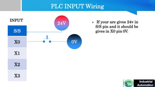
What is Sink and Source:-Sink and source refer to the direction
of current flow between an I/O point on an I/O module and the connected
device. It is only relevant for DC circuits with positive and negative
polarities since current flows both directions in an AC circuit.more
explain..
S/S
X0
X1
X2
X3
INPUT
S/S
X0
0V
24V
24V
0V
_
+
_
+
This Circuit Call Opto
couplor
• If input 24v
then we gives
S/S 0V so it will
be depand on
INPUT
PLC INPUT Wiring
S/S
X0
X1
X2
X3
INPUT
24V
0V
 If your are gives 24v in
S/S pin and it should be
gives in X0 pin 0V.
PLC INPUT Wirnig
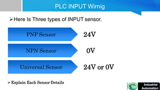
Here Is Three types of INPUT sensor.
PNP Sensor
NPN Sensor
Universal Sensor
24V
0V
24V or 0V
Explain Each Sensor Details
PLC INPUT Wiring
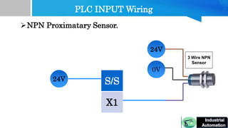
NPN Proximatary Sensor.
24V
0V
S/S
X1
24V
3 Wire NPN
Sensor
PLC INPUT Wiring
PNP Proximatary Sensor.
24V
0V
S/S
X1
0V
3 Wire PNP
Sensor
PLC INPUT Wiring
Universal Proximatary Sensor.
24v
0v
24v
0v
PLC OUTPUT Wiring
Hear Is Two Types Of PLC output.
Transistor Type
Output
Relay Type
Output
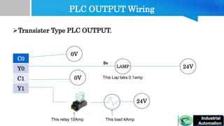
 Transistor type PLC output capcity 0.1A as per PLC
configuration so we can not use havy load out put.
 If you want to use havy load output in transistor type
plc you can use external rely then we use havy load
output.
 Transistor type PLC mostly use in high speed
application.e.g Servo motor,steppar motor etc.
 Relay Type PLC have 1A to 10A capacity so wecan
directly use havy load output.
 its was used in genral purpos
motor,contector,solenoid valve application
PLC OUTPUT Wiring
0V
LAMP 24V
0v
This Lap taks 0.1amp
Transister Type PLC OUTPUT.
C0
Y0
C1
Y1
0V
This load 4Amp
This relay 10Amp
24V
PLC OUTPUT Wiring
0V
LAMP 24V
0v
This Lap taks 0.1amp
Relay Type PLC OUTPUT.
C0
Y0
C1
Y1
0V
24V
This load 4Amp
PLC Wiring
and
Programming
PLC Wirning and Programming
From PLC Wiring to pogramming !!
From PLC Wiring to pogramming
S/S
X0
X1
X2
C
Y0
Y1
Y2
INPUT OUTPUT
24V
0V
0V
24V
This is Software Part
This Is a Hardware Part
X0
X1
Y0
Y1
This Is Normally
Open Contact
Output
Coil
PLC Relay Latching
and Unlatching
PLC Relay Lathing and Unlatching
Relay
 Relay Configuration.
IEC255
5A 250VAC~
5A 240VAC
5A 28Vdc
This Relay Have a 10Amps
capacity.
PLC Relay Lathing and Unlatching
24V 0V
Relay
NO Switch
NO Contact
This is Latching
13 14
5 6
Relay Common
Relay NO
24V 0V
Relay
NO Switch
NO Contact
PLC Relay Lathing and Unlatching
This is UnLatching
NC Switch
5 6
13 14
`
PLC Relay Lathing and Unlatching
Relay Important.
1. Check Coil rating:- 5 Vdc
12 Vdc
24 Vdc
110 Vac
240 Vac
2. Contact rating:-10Amp
Let's We can chacke example why we alwasy chacke contact
rating.
PLC Relay Lathing and Unlatching
• Example:-
L
N
MOTOR
220v
Motor
5Amp
singal
pahse
motor
10Amps
relay
NO
C
PLC Relay Lathing and Unlatching
Motor
Object
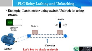
• Example:-Latch motor using switch Unlatch its using
sensor.
Sensor
ON OFF
ON / OFF
Switch
Conveyor
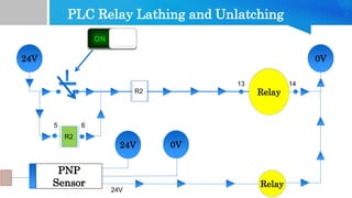
Let's See we chcek on circuit
PLC Relay Lathing and Unlatching
24V 0V
R2
Relay
NO Switch
13 14
5 6
PNP
Sensor
24V 0V
24V
R2
Relay
R2

More Related Content

Similar to plc_scada.pptx

Part 3 block diagram of PLC.
Part 3 block diagram of PLC.Part 3 block diagram of PLC.
Part 3 block diagram of PLC.
KuldeepMakwana6
 
Plc
PlcPlc
Basic PLC
Basic PLCBasic PLC
Basic PLC
Hammzah Niazi
 
Basic PLC.ppt
Basic PLC.pptBasic PLC.ppt
Basic PLC.ppt
RaghadAlnajim1
 
Basic plc
Basic plcBasic plc
Programmable Logic Controller Training Day 1 to 3.pptx
Programmable Logic Controller  Training Day 1 to 3.pptxProgrammable Logic Controller  Training Day 1 to 3.pptx
Programmable Logic Controller Training Day 1 to 3.pptx
dmckinseyrecruitment
 
Basic plc
Basic plcBasic plc
Basic plc
gmvd201091
 
Basic plc
Basic plcBasic plc
Basic plc
mnamky
 
Basic plc
Basic plcBasic plc
Basic plc
kaishik gundu
 
Basic plc
Basic plcBasic plc
Basic plc
shubhammanit
 
Unit 4 - PLC.pptx
Unit 4 - PLC.pptxUnit 4 - PLC.pptx
Unit 4 - PLC.pptx
Charunnath S V
 
PLC-converted.pdf
PLC-converted.pdfPLC-converted.pdf
PLC-converted.pdf
SaidAbouzeid1
 
Basics and applications of programmable logic controller (plc)
Basics and applications of programmable logic controller (plc)Basics and applications of programmable logic controller (plc)
Basics and applications of programmable logic controller (plc)
Ali Altahir
 
MECHATRONICS-UNIT 4-PROGRAMMABLE LOGIC CONTROLLER .ppt
MECHATRONICS-UNIT 4-PROGRAMMABLE LOGIC CONTROLLER .pptMECHATRONICS-UNIT 4-PROGRAMMABLE LOGIC CONTROLLER .ppt
MECHATRONICS-UNIT 4-PROGRAMMABLE LOGIC CONTROLLER .ppt
CHANDRA KUMAR S
 

Similar to plc_scada.pptx (20)

Part 3 block diagram of PLC.
Part 3 block diagram of PLC.Part 3 block diagram of PLC.
Part 3 block diagram of PLC.
 
Plc
PlcPlc
Plc
 
Basic PLC
Basic PLCBasic PLC
Basic PLC
 
Basic PLC.ppt
Basic PLC.pptBasic PLC.ppt
Basic PLC.ppt
 
Basic PLC.ppt
Basic PLC.pptBasic PLC.ppt
Basic PLC.ppt
 
Basic plc
Basic plcBasic plc
Basic plc
 
Programmable Logic Controller Training Day 1 to 3.pptx
Programmable Logic Controller  Training Day 1 to 3.pptxProgrammable Logic Controller  Training Day 1 to 3.pptx
Programmable Logic Controller Training Day 1 to 3.pptx
 
Basic plc
Basic plcBasic plc
Basic plc
 
Basic plc
Basic plcBasic plc
Basic plc
 
Basic plc
Basic plcBasic plc
Basic plc
 
Basic plc
Basic plcBasic plc
Basic plc
 
Basic plc
Basic plcBasic plc
Basic plc
 
Basic plc
Basic plcBasic plc
Basic plc
 
Basic plc
Basic plcBasic plc
Basic plc
 
Basic plc
Basic plcBasic plc
Basic plc
 
Basic plc
Basic plcBasic plc
Basic plc
 
Unit 4 - PLC.pptx
Unit 4 - PLC.pptxUnit 4 - PLC.pptx
Unit 4 - PLC.pptx
 
PLC-converted.pdf
PLC-converted.pdfPLC-converted.pdf
PLC-converted.pdf
 
Basics and applications of programmable logic controller (plc)
Basics and applications of programmable logic controller (plc)Basics and applications of programmable logic controller (plc)
Basics and applications of programmable logic controller (plc)
 
MECHATRONICS-UNIT 4-PROGRAMMABLE LOGIC CONTROLLER .ppt
MECHATRONICS-UNIT 4-PROGRAMMABLE LOGIC CONTROLLER .pptMECHATRONICS-UNIT 4-PROGRAMMABLE LOGIC CONTROLLER .ppt
MECHATRONICS-UNIT 4-PROGRAMMABLE LOGIC CONTROLLER .ppt
 

Recently uploaded

ASME IX(9) 2007 Full Version .pdf
ASME IX(9)  2007 Full Version       .pdfASME IX(9)  2007 Full Version       .pdf
ASME IX(9) 2007 Full Version .pdf
AhmedHussein950959
 
Hierarchical Digital Twin of a Naval Power System
Hierarchical Digital Twin of a Naval Power SystemHierarchical Digital Twin of a Naval Power System
Hierarchical Digital Twin of a Naval Power System
Kerry Sado
 
一比一原版(UofT毕业证)多伦多大学毕业证成绩单如何办理
一比一原版(UofT毕业证)多伦多大学毕业证成绩单如何办理一比一原版(UofT毕业证)多伦多大学毕业证成绩单如何办理
一比一原版(UofT毕业证)多伦多大学毕业证成绩单如何办理
ydteq
 
NO1 Uk best vashikaran specialist in delhi vashikaran baba near me online vas...
NO1 Uk best vashikaran specialist in delhi vashikaran baba near me online vas...NO1 Uk best vashikaran specialist in delhi vashikaran baba near me online vas...
NO1 Uk best vashikaran specialist in delhi vashikaran baba near me online vas...
Amil Baba Dawood bangali
 
H.Seo, ICLR 2024, MLILAB, KAIST AI.pdf
H.Seo,  ICLR 2024, MLILAB,  KAIST AI.pdfH.Seo,  ICLR 2024, MLILAB,  KAIST AI.pdf
H.Seo, ICLR 2024, MLILAB, KAIST AI.pdf
MLILAB
 
MCQ Soil mechanics questions (Soil shear strength).pdf
MCQ Soil mechanics questions (Soil shear strength).pdfMCQ Soil mechanics questions (Soil shear strength).pdf
MCQ Soil mechanics questions (Soil shear strength).pdf
Osamah Alsalih
 
Top 10 Oil and Gas Projects in Saudi Arabia 2024.pdf
Top 10 Oil and Gas Projects in Saudi Arabia 2024.pdfTop 10 Oil and Gas Projects in Saudi Arabia 2024.pdf
Top 10 Oil and Gas Projects in Saudi Arabia 2024.pdf
Teleport Manpower Consultant
 
Gen AI Study Jams _ For the GDSC Leads in India.pdf
Gen AI Study Jams _ For the GDSC Leads in India.pdfGen AI Study Jams _ For the GDSC Leads in India.pdf
Gen AI Study Jams _ For the GDSC Leads in India.pdf
gdsczhcet
 
ML for identifying fraud using open blockchain data.pptx
ML for identifying fraud using open blockchain data.pptxML for identifying fraud using open blockchain data.pptx
ML for identifying fraud using open blockchain data.pptx
Vijay Dialani, PhD
 
The Benefits and Techniques of Trenchless Pipe Repair.pdf
The Benefits and Techniques of Trenchless Pipe Repair.pdfThe Benefits and Techniques of Trenchless Pipe Repair.pdf
The Benefits and Techniques of Trenchless Pipe Repair.pdf
Pipe Restoration Solutions
 
Industrial Training at Shahjalal Fertilizer Company Limited (SFCL)
Industrial Training at Shahjalal Fertilizer Company Limited (SFCL)Industrial Training at Shahjalal Fertilizer Company Limited (SFCL)
Industrial Training at Shahjalal Fertilizer Company Limited (SFCL)
MdTanvirMahtab2
 
ethical hacking in wireless-hacking1.ppt
ethical hacking in wireless-hacking1.pptethical hacking in wireless-hacking1.ppt
ethical hacking in wireless-hacking1.ppt
Jayaprasanna4
 
在线办理(ANU毕业证书)澳洲国立大学毕业证录取通知书一模一样
在线办理(ANU毕业证书)澳洲国立大学毕业证录取通知书一模一样在线办理(ANU毕业证书)澳洲国立大学毕业证录取通知书一模一样
在线办理(ANU毕业证书)澳洲国立大学毕业证录取通知书一模一样
obonagu
 
RAT: Retrieval Augmented Thoughts Elicit Context-Aware Reasoning in Long-Hori...
RAT: Retrieval Augmented Thoughts Elicit Context-Aware Reasoning in Long-Hori...RAT: Retrieval Augmented Thoughts Elicit Context-Aware Reasoning in Long-Hori...
RAT: Retrieval Augmented Thoughts Elicit Context-Aware Reasoning in Long-Hori...
thanhdowork
 
CME397 Surface Engineering- Professional Elective
CME397 Surface Engineering- Professional ElectiveCME397 Surface Engineering- Professional Elective
CME397 Surface Engineering- Professional Elective
karthi keyan
 
AP LAB PPT.pdf ap lab ppt no title specific
AP LAB PPT.pdf ap lab ppt no title specificAP LAB PPT.pdf ap lab ppt no title specific
AP LAB PPT.pdf ap lab ppt no title specific
BrazilAccount1
 
weather web application report.pdf
weather web application report.pdfweather web application report.pdf
weather web application report.pdf
Pratik Pawar
 
Immunizing Image Classifiers Against Localized Adversary Attacks
Immunizing Image Classifiers Against Localized Adversary AttacksImmunizing Image Classifiers Against Localized Adversary Attacks
Immunizing Image Classifiers Against Localized Adversary Attacks
gerogepatton
 
J.Yang, ICLR 2024, MLILAB, KAIST AI.pdf
J.Yang,  ICLR 2024, MLILAB, KAIST AI.pdfJ.Yang,  ICLR 2024, MLILAB, KAIST AI.pdf
J.Yang, ICLR 2024, MLILAB, KAIST AI.pdf
MLILAB
 
Architectural Portfolio Sean Lockwood
Architectural Portfolio Sean LockwoodArchitectural Portfolio Sean Lockwood
Architectural Portfolio Sean Lockwood
seandesed
 

Recently uploaded (20)

ASME IX(9) 2007 Full Version .pdf
ASME IX(9)  2007 Full Version       .pdfASME IX(9)  2007 Full Version       .pdf
ASME IX(9) 2007 Full Version .pdf
 
Hierarchical Digital Twin of a Naval Power System
Hierarchical Digital Twin of a Naval Power SystemHierarchical Digital Twin of a Naval Power System
Hierarchical Digital Twin of a Naval Power System
 
一比一原版(UofT毕业证)多伦多大学毕业证成绩单如何办理
一比一原版(UofT毕业证)多伦多大学毕业证成绩单如何办理一比一原版(UofT毕业证)多伦多大学毕业证成绩单如何办理
一比一原版(UofT毕业证)多伦多大学毕业证成绩单如何办理
 
NO1 Uk best vashikaran specialist in delhi vashikaran baba near me online vas...
NO1 Uk best vashikaran specialist in delhi vashikaran baba near me online vas...NO1 Uk best vashikaran specialist in delhi vashikaran baba near me online vas...
NO1 Uk best vashikaran specialist in delhi vashikaran baba near me online vas...
 
H.Seo, ICLR 2024, MLILAB, KAIST AI.pdf
H.Seo,  ICLR 2024, MLILAB,  KAIST AI.pdfH.Seo,  ICLR 2024, MLILAB,  KAIST AI.pdf
H.Seo, ICLR 2024, MLILAB, KAIST AI.pdf
 
MCQ Soil mechanics questions (Soil shear strength).pdf
MCQ Soil mechanics questions (Soil shear strength).pdfMCQ Soil mechanics questions (Soil shear strength).pdf
MCQ Soil mechanics questions (Soil shear strength).pdf
 
Top 10 Oil and Gas Projects in Saudi Arabia 2024.pdf
Top 10 Oil and Gas Projects in Saudi Arabia 2024.pdfTop 10 Oil and Gas Projects in Saudi Arabia 2024.pdf
Top 10 Oil and Gas Projects in Saudi Arabia 2024.pdf
 
Gen AI Study Jams _ For the GDSC Leads in India.pdf
Gen AI Study Jams _ For the GDSC Leads in India.pdfGen AI Study Jams _ For the GDSC Leads in India.pdf
Gen AI Study Jams _ For the GDSC Leads in India.pdf
 
ML for identifying fraud using open blockchain data.pptx
ML for identifying fraud using open blockchain data.pptxML for identifying fraud using open blockchain data.pptx
ML for identifying fraud using open blockchain data.pptx
 
The Benefits and Techniques of Trenchless Pipe Repair.pdf
The Benefits and Techniques of Trenchless Pipe Repair.pdfThe Benefits and Techniques of Trenchless Pipe Repair.pdf
The Benefits and Techniques of Trenchless Pipe Repair.pdf
 
Industrial Training at Shahjalal Fertilizer Company Limited (SFCL)
Industrial Training at Shahjalal Fertilizer Company Limited (SFCL)Industrial Training at Shahjalal Fertilizer Company Limited (SFCL)
Industrial Training at Shahjalal Fertilizer Company Limited (SFCL)
 
ethical hacking in wireless-hacking1.ppt
ethical hacking in wireless-hacking1.pptethical hacking in wireless-hacking1.ppt
ethical hacking in wireless-hacking1.ppt
 
在线办理(ANU毕业证书)澳洲国立大学毕业证录取通知书一模一样
在线办理(ANU毕业证书)澳洲国立大学毕业证录取通知书一模一样在线办理(ANU毕业证书)澳洲国立大学毕业证录取通知书一模一样
在线办理(ANU毕业证书)澳洲国立大学毕业证录取通知书一模一样
 
RAT: Retrieval Augmented Thoughts Elicit Context-Aware Reasoning in Long-Hori...
RAT: Retrieval Augmented Thoughts Elicit Context-Aware Reasoning in Long-Hori...RAT: Retrieval Augmented Thoughts Elicit Context-Aware Reasoning in Long-Hori...
RAT: Retrieval Augmented Thoughts Elicit Context-Aware Reasoning in Long-Hori...
 
CME397 Surface Engineering- Professional Elective
CME397 Surface Engineering- Professional ElectiveCME397 Surface Engineering- Professional Elective
CME397 Surface Engineering- Professional Elective
 
AP LAB PPT.pdf ap lab ppt no title specific
AP LAB PPT.pdf ap lab ppt no title specificAP LAB PPT.pdf ap lab ppt no title specific
AP LAB PPT.pdf ap lab ppt no title specific
 
weather web application report.pdf
weather web application report.pdfweather web application report.pdf
weather web application report.pdf
 
Immunizing Image Classifiers Against Localized Adversary Attacks
Immunizing Image Classifiers Against Localized Adversary AttacksImmunizing Image Classifiers Against Localized Adversary Attacks
Immunizing Image Classifiers Against Localized Adversary Attacks
 
J.Yang, ICLR 2024, MLILAB, KAIST AI.pdf
J.Yang,  ICLR 2024, MLILAB, KAIST AI.pdfJ.Yang,  ICLR 2024, MLILAB, KAIST AI.pdf
J.Yang, ICLR 2024, MLILAB, KAIST AI.pdf
 
Architectural Portfolio Sean Lockwood
Architectural Portfolio Sean LockwoodArchitectural Portfolio Sean Lockwood
Architectural Portfolio Sean Lockwood
 

plc_scada.pptx

  • 2. Before the Programmable controller • Control system implemented using relay controller. • Lack of flexibilty for process changes or expansion • Troubleshooting: Five hours to find and five minutes to fix,it.
  • 3. History of PLC • Before The days of the PLC The only way to control mahinery was through the use of relays. • PLC was Introduction in late 1960's • First Commorercial and successful programmable logic controllers was designed and devloped by modicon as a relay replacer for general motors. • Earlier it was a machine with thousands of electronic parts.
  • 4. What is a PLC ?
  • 5. Why PLC Use ? PLC OUTPUT PUSH BUTTON INPUT Motor A PLC is a solid state/Computerized industrial computer that performs discrete( 0 , 1 ) or sequential logic in a factory environment its called PLC PLC:- Programmable Logic control
  • 6. What Is PLC.. What is Sequential:- it means when you press a switch then start light one by one. What is Discrete:- It means when you press a switch then start all light. It was originally developed to replace mechanical relay,Timer,Counters.PLC are used successfully to execute complicated control operations in a plant.
  • 11. Application  In boilers – Thermal Power Plants
  • 13. Advantages  Reliability  Flexibility in programming and reprogramming  Cost effective for controlling complex systems.  Small Physical size, shorter project time.  High Speed of operation.  Ability to communicate With computer systems in the plant.  Ease of maintenance / troubleshooting.  Reduced space.  Energy Saving
  • 14. Disadvantages  PLC device are proprietor it means that part or software of one manufacturer can't be used in combination with parts of another manufacturer.  Limited design and cost option.  Fixed Circuit operations.  PLCs manufacturers offer only closed architectures.
  • 15. Block Diagram of PLC & Components of PLC
  • 16. Block Diagram of PLC Programming Communication Device Central Processing Unit (CPU) Memory Program Power Supply INPUT Circuit (Field Area) OUTPUT Circuit (Field Area) Optical Isolation Optical Isolation
  • 17. Components of PLC  CPU(Central Processing unit)  INPUT Module  OUTPUT Module  Power Supply  Programming Device
  • 18. Components of PLC  CUP(Central Processing unit):- • CPU module has a central processor, ROM & RAM memory. • ROM memory includes operating system, driver and application program. RAM memory is used to store programs and data. • CPU is the brain of PLC with an octal or hexagonal microprocessor. Being a microprocessor based CPU, it replaces timers, relays, and counters. • Two types of processors as a single bit or word processor can be incorporated with a PLC. • CPU reads the input data from sensors, process it and finally the command to controlling devices.
  • 19. Components of PLC CPU consist of following blocks • ALU(Arithmetic Logic Unit) • Programming memory. • Process image memory. • Internal timer and counter. • Flags or status bit filter. • CPU required 5v.
  • 20. Components of PLC INPUT MODULE:- • Input module act as an interface between the field control input and the CPU voltage/current generated by the sensors,transducer,limit switch,push button,etc. • Input module converts the field signal into standard control signal for processing by the PLC • The input module of PLC does four main functions. 1. Input module interface receives the signal from process devices at 220 V AC 2. Converts the input signal to 5 V DC that can be used by PLC 3. Isolator block is used to isolate/prevent PLC from undergoing fluctuation 4. After which the signal is sent to the output end i.e the PLC
  • 21. Components of PLC OUTPUT Module:-  Output Module acts as link between the CPU and the output devices located in the field devices could be relays,contaector,lamps,motorized actuators, solenoid valves,etc.These device actually control the process.
  • 22. Power Supply:-  This module is used to provide the required power to the whole PLC system.  It converts the available AC power to DC power which is required by the CPU and I/O module. PLC generally works on 24V DC supply and Rack type PLC work on 230/220Vac. Few PLC uses an isolated power supply.
  • 23. Components of PLC Programming Device:-  A personal computer(PC) is the most commonly used programming device.The software allows users to create,edit,store and troubleshoot programs.  This is show pitchure id programming cable Rs-232 and Ethernet cabl for Programming cable RS-232 Cable Ethernet Cable
  • 24. Next Video Topic  Types of PLC.
  • 26. Types of PLC Types of PLC Moduler PLC Compact PLC
  • 27. Moduler Type PLC • This type of PLC permits multiple expansion through “modules”, hence referred to as Modular PLC. • I/O components can be increased. • It is easier to use because each component is independent of each other. A Moduler TypePLC
  • 28. Compact Type PLC Within a single case, there would be many modules. It has a fixed number of I/O modules and external I/O cards. So, it does not have the capability to expand the modules. Every input and output would be decided by the manufacturer. PLC are divided into three types based on output namely Relay output, Transistor output, and Triac Output PLC. The relay output type is best suited for both AC and DC output devices. Transistor output type PLC uses switching operations and used inside microprocessors.
  • 30. Here Is Two Types Of Input / Output Module. 1. Analog Module:- Analog Input and out module work it's shoud be 0v ~ 10v , 4ma ~ 20ma , -20ma ~ 20ma. 2. Digital Module:- Digital Input and output module work it's should be '0' and '1'. Digtal Module Analog Module
  • 31. Signal of Inputs ans Outputs module Digital Type Analog Type Input Output • Push Buttons • Switch • Limit Switch • Proximity sensor • Photo Sensors • Relay • Contactors • Lamps • Alarm Hotters • LED • Solinoid Valved • Coils Input Output • RTD (Temp Sensor) • Thermocouple • Transducers • Transmitter • Drive (Analog Port) • Actuator • Valve Position
  • 33. PLC Programming Languages Ladder Diagram (LD) Structured Text (ST) Sequential Function Chart (SFC) Function Block Diagram (FBD) Instruction List (IL)
  • 34. Ladder Diagram (LD) Ladder Logic  Ladder logic is the simplest from of PLC programming It is also known as “Relay logic”.  The Relay contacts used in relay controlled systems are represented using ladder logic.we check example. In the mentioned example, two pushbuttons are used to control the same lamp load. When any one of the switches is closed, the lamp will glow. The two horizontal lines are called rungs and two vertical lines are called rails. Every rung forms the electrical connectivity between Positive rail (P) and Negative rail (N). This allows the current to flow between input and output devices.
  • 35. Function Block Diagram  Functional Block Diagram (FBD) is a simple and graphical method to program multiple functions in PLC.  PLC Open has described using FBD in the standard IEC 61131-3. A function block is a program instruction unit that, when executed, yields one or more output values.It is represented by a block as shown fig. It is represented as a rectangular block with inputs entering on left and output lines leaving at the right. It gives a relation between the state of input and output
  • 37. PLC SCAN TIME BASICS CONCEPT PLC SCAN CYCLE INPUT SIGNAL LOGIC SOLVE OUTPUT SIGNAL Input Read NO,NC,OUTPUT COIL,TMR,CNT Output Write PLC Scan Time LOOP LOOP INPUT Signal Read + LOGIC SOLVE + OUTPUT Write = PLC SCAN TIME
  • 38. PLC SCAN TIME Read Input Logic Solve Update Output PLC Scan Cycle • What is a ScanTime:- It is the time taken PLC to read INPUT process the logic Solve and update OUTPUT in one cycle its called Scan Time. • PLC SCAN Time Depends on No.of inputs,length of logic,and No.of Outputs. • This Process in LOOP • PLC Scan time very between 0.1ms to 50ms.
  • 39. PLC SCAN TIME NO.of Inputs Length of Logic  Analog module each channel taken 3ms.  PLC Scan Time Depands in below three parts No.of Outputs Scan time depands on this three parts
  • 41. PLC Fundamantel • What Is PLC ????? Programmable Logic Controller Hardware - Ladder Logic - FBD - SFC Reprogramming • Let's come next page how to use thsi systemparcticaly
  • 42. PLC Fundamantel • Example:- Water Level Control INPUT OUTPUT Processor PLC 80% 60% 40% 20% 0% NO/OFF Valve Automatic Manualy Valve Tank • This System INPUT is User level requirment like 50% ,80% ,20%. • And Output is solenoid valve • This All system runing in processor means this work on PLC.so this is functioning of PLC. • This Fundamantel of PLC...
  • 43. PLC INPUT Wiring What is Sink and Source:-Sink and source refer to the direction of current flow between an I/O point on an I/O module and the connected device. It is only relevant for DC circuits with positive and negative polarities since current flows both directions in an AC circuit.more explain.. S/S X0 X1 X2 X3 INPUT S/S X0 0V 24V 24V 0V _ + _ + This Circuit Call Opto couplor • If input 24v then we gives S/S 0V so it will be depand on INPUT
  • 44. PLC INPUT Wiring S/S X0 X1 X2 X3 INPUT 24V 0V  If your are gives 24v in S/S pin and it should be gives in X0 pin 0V.
  • 45. PLC INPUT Wirnig Here Is Three types of INPUT sensor. PNP Sensor NPN Sensor Universal Sensor 24V 0V 24V or 0V Explain Each Sensor Details
  • 46. PLC INPUT Wiring NPN Proximatary Sensor. 24V 0V S/S X1 24V 3 Wire NPN Sensor
  • 47. PLC INPUT Wiring PNP Proximatary Sensor. 24V 0V S/S X1 0V 3 Wire PNP Sensor
  • 48. PLC INPUT Wiring Universal Proximatary Sensor. 24v 0v 24v 0v
  • 49. PLC OUTPUT Wiring Hear Is Two Types Of PLC output. Transistor Type Output Relay Type Output  Transistor type PLC output capcity 0.1A as per PLC configuration so we can not use havy load out put.  If you want to use havy load output in transistor type plc you can use external rely then we use havy load output.  Transistor type PLC mostly use in high speed application.e.g Servo motor,steppar motor etc.  Relay Type PLC have 1A to 10A capacity so wecan directly use havy load output.  its was used in genral purpos motor,contector,solenoid valve application
  • 50. PLC OUTPUT Wiring 0V LAMP 24V 0v This Lap taks 0.1amp Transister Type PLC OUTPUT. C0 Y0 C1 Y1 0V This load 4Amp This relay 10Amp 24V
  • 51. PLC OUTPUT Wiring 0V LAMP 24V 0v This Lap taks 0.1amp Relay Type PLC OUTPUT. C0 Y0 C1 Y1 0V 24V This load 4Amp
  • 53. PLC Wirning and Programming From PLC Wiring to pogramming !!
  • 54. From PLC Wiring to pogramming S/S X0 X1 X2 C Y0 Y1 Y2 INPUT OUTPUT 24V 0V 0V 24V This is Software Part This Is a Hardware Part X0 X1 Y0 Y1 This Is Normally Open Contact Output Coil
  • 56. PLC Relay Lathing and Unlatching Relay  Relay Configuration. IEC255 5A 250VAC~ 5A 240VAC 5A 28Vdc This Relay Have a 10Amps capacity.
  • 57. PLC Relay Lathing and Unlatching 24V 0V Relay NO Switch NO Contact This is Latching 13 14 5 6 Relay Common Relay NO
  • 58. 24V 0V Relay NO Switch NO Contact PLC Relay Lathing and Unlatching This is UnLatching NC Switch 5 6 13 14
  • 59. ` PLC Relay Lathing and Unlatching Relay Important. 1. Check Coil rating:- 5 Vdc 12 Vdc 24 Vdc 110 Vac 240 Vac 2. Contact rating:-10Amp Let's We can chacke example why we alwasy chacke contact rating.
  • 60. PLC Relay Lathing and Unlatching • Example:- L N MOTOR 220v Motor 5Amp singal pahse motor 10Amps relay NO C
  • 61. PLC Relay Lathing and Unlatching Motor Object • Example:-Latch motor using switch Unlatch its using sensor. Sensor ON OFF ON / OFF Switch Conveyor Let's See we chcek on circuit
  • 62. PLC Relay Lathing and Unlatching 24V 0V R2 Relay NO Switch 13 14 5 6 PNP Sensor 24V 0V 24V R2 Relay R2