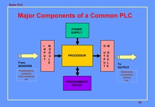
This document provides an overview of a basic PLC training course. It describes the major components of a PLC including the processor, memory, I/O modules, and programming device. It also outlines the course contents which will cover the history of PLCs, programming concepts, applications, and troubleshooting. The objectives are for participants to understand PLC components, programming, applications, and basic troubleshooting.
Seminar Presentation on Programmeble Logic Controller , By an Engineering Student For doing Professional Presentation like Business Presentation, Industrial Use
Hi friends
This PPT consist of automation information ,what is PLC,need of PLC applications,components of PLC ,PLC operations,Timers , Some Program, etc
instead of this it consists SCADA ,what is SCADA,need of SCADA,brands of SCADA, tags ,features of SCADA, Dynamic process graphic , script security etc.......
PowerPoint Presentation on Industrial Automation In which we discuss About PLCs, SCADA,HMI,VFD and various tools of Automation which is used in Industries.
Like Comment & Share
Seminar Presentation on Programmeble Logic Controller , By an Engineering Student For doing Professional Presentation like Business Presentation, Industrial automation process,
PLC is an industrial computer designed for multiple inputs and output arrangements. It is capable of storing the instructions to implement control functions such as sequencing, timing, counting, arithmetic, data manipulation and communication.
A programmable logic controller (PLC) or programmable controller is an industrial digital computer which has been ruggedized and adapted for the control of manufacturing processes, such as assembly lines, or robotic devices, or any activity that requires high reliability, ease of programming and process fault diagnosis.
Basics and applications of programmable logic controller (plc)Ali Altahir
PLC is a multipurpose clock-driven memory-based electronic device which is also known as a specialized industrial computer which deals with different level of complexity and control system.
A PLC is a digital operating electronic apparatus.
Which uses a programmable memory for internal storage of instruction for implementing specific function such as logic, sequencing, timing, counting and arithmetic to control through analog or digital input/output modules various types of machines or process.
Mechatronics is a multidisciplinary field that refers to the skill sets needed in the contemporary, advanced automated manufacturing industry. At the intersection of mechanics, electronics, and computing, mechatronics specialists create simpler, smarter systems.
COLLEGE BUS MANAGEMENT SYSTEM PROJECT REPORT.pdfKamal Acharya
The College Bus Management system is completely developed by Visual Basic .NET Version. The application is connect with most secured database language MS SQL Server. The application is develop by using best combination of front-end and back-end languages. The application is totally design like flat user interface. This flat user interface is more attractive user interface in 2017. The application is gives more important to the system functionality. The application is to manage the student’s details, driver’s details, bus details, bus route details, bus fees details and more. The application has only one unit for admin. The admin can manage the entire application. The admin can login into the application by using username and password of the admin. The application is develop for big and small colleges. It is more user friendly for non-computer person. Even they can easily learn how to manage the application within hours. The application is more secure by the admin. The system will give an effective output for the VB.Net and SQL Server given as input to the system. The compiled java program given as input to the system, after scanning the program will generate different reports. The application generates the report for users. The admin can view and download the report of the data. The application deliver the excel format reports. Because, excel formatted reports is very easy to understand the income and expense of the college bus. This application is mainly develop for windows operating system users. In 2017, 73% of people enterprises are using windows operating system. So the application will easily install for all the windows operating system users. The application-developed size is very low. The application consumes very low space in disk. Therefore, the user can allocate very minimum local disk space for this application.
Final project report on grocery store management system..pdfKamal Acharya
In today’s fast-changing business environment, it’s extremely important to be able to respond to client needs in the most effective and timely manner. If your customers wish to see your business online and have instant access to your products or services.
Online Grocery Store is an e-commerce website, which retails various grocery products. This project allows viewing various products available enables registered users to purchase desired products instantly using Paytm, UPI payment processor (Instant Pay) and also can place order by using Cash on Delivery (Pay Later) option. This project provides an easy access to Administrators and Managers to view orders placed using Pay Later and Instant Pay options.
In order to develop an e-commerce website, a number of Technologies must be studied and understood. These include multi-tiered architecture, server and client-side scripting techniques, implementation technologies, programming language (such as PHP, HTML, CSS, JavaScript) and MySQL relational databases. This is a project with the objective to develop a basic website where a consumer is provided with a shopping cart website and also to know about the technologies used to develop such a website.
This document will discuss each of the underlying technologies to create and implement an e- commerce website.
Student information management system project report ii.pdfKamal Acharya
Our project explains about the student management. This project mainly explains the various actions related to student details. This project shows some ease in adding, editing and deleting the student details. It also provides a less time consuming process for viewing, adding, editing and deleting the marks of the students.
Sachpazis:Terzaghi Bearing Capacity Estimation in simple terms with Calculati...Dr.Costas Sachpazis
Terzaghi's soil bearing capacity theory, developed by Karl Terzaghi, is a fundamental principle in geotechnical engineering used to determine the bearing capacity of shallow foundations. This theory provides a method to calculate the ultimate bearing capacity of soil, which is the maximum load per unit area that the soil can support without undergoing shear failure. The Calculation HTML Code included.
TECHNICAL TRAINING MANUAL GENERAL FAMILIARIZATION COURSEDuvanRamosGarzon1
AIRCRAFT GENERAL
The Single Aisle is the most advanced family aircraft in service today, with fly-by-wire flight controls.
The A318, A319, A320 and A321 are twin-engine subsonic medium range aircraft.
The family offers a choice of engines
Event Management System Vb Net Project Report.pdfKamal Acharya
In present era, the scopes of information technology growing with a very fast .We do not see any are untouched from this industry. The scope of information technology has become wider includes: Business and industry. Household Business, Communication, Education, Entertainment, Science, Medicine, Engineering, Distance Learning, Weather Forecasting. Carrier Searching and so on.
My project named “Event Management System” is software that store and maintained all events coordinated in college. It also helpful to print related reports. My project will help to record the events coordinated by faculties with their Name, Event subject, date & details in an efficient & effective ways.
In my system we have to make a system by which a user can record all events coordinated by a particular faculty. In our proposed system some more featured are added which differs it from the existing system such as security.
Automobile Management System Project Report.pdfKamal Acharya
The proposed project is developed to manage the automobile in the automobile dealer company. The main module in this project is login, automobile management, customer management, sales, complaints and reports. The first module is the login. The automobile showroom owner should login to the project for usage. The username and password are verified and if it is correct, next form opens. If the username and password are not correct, it shows the error message.
When a customer search for a automobile, if the automobile is available, they will be taken to a page that shows the details of the automobile including automobile name, automobile ID, quantity, price etc. “Automobile Management System” is useful for maintaining automobiles, customers effectively and hence helps for establishing good relation between customer and automobile organization. It contains various customized modules for effectively maintaining automobiles and stock information accurately and safely.
When the automobile is sold to the customer, stock will be reduced automatically. When a new purchase is made, stock will be increased automatically. While selecting automobiles for sale, the proposed software will automatically check for total number of available stock of that particular item, if the total stock of that particular item is less than 5, software will notify the user to purchase the particular item.
Also when the user tries to sale items which are not in stock, the system will prompt the user that the stock is not enough. Customers of this system can search for a automobile; can purchase a automobile easily by selecting fast. On the other hand the stock of automobiles can be maintained perfectly by the automobile shop manager overcoming the drawbacks of existing system.
Explore the innovative world of trenchless pipe repair with our comprehensive guide, "The Benefits and Techniques of Trenchless Pipe Repair." This document delves into the modern methods of repairing underground pipes without the need for extensive excavation, highlighting the numerous advantages and the latest techniques used in the industry.
Learn about the cost savings, reduced environmental impact, and minimal disruption associated with trenchless technology. Discover detailed explanations of popular techniques such as pipe bursting, cured-in-place pipe (CIPP) lining, and directional drilling. Understand how these methods can be applied to various types of infrastructure, from residential plumbing to large-scale municipal systems.
Ideal for homeowners, contractors, engineers, and anyone interested in modern plumbing solutions, this guide provides valuable insights into why trenchless pipe repair is becoming the preferred choice for pipe rehabilitation. Stay informed about the latest advancements and best practices in the field.
2. Basic PLC
2
Description
This training introduces the basic hardware and software
components of a Programmable Controller (PLC). It
details the architecture and basic instruction set common
to all PLC’s. Basic programming techniques and logic
designs are covered. This training describes the
operating features of the PLC, the advantages of the
PLC over hard-wired control systems, practical
applications, troubleshooting and maintenance of PLC’s.
3. Basic PLC
3
Objectives
At the end of the training the participants should be able
to:
Describe the major components of a common PLC.
Interpret PLC specifications.
Apply troubleshooting techniques.
Convert conventional relay logic to a PLC language.
Operate and program a PLC for a given application.
4. Basic PLC
4
Course Contents
History of Programmable Controllers
Relay Ladder Logic
Central Processing Unit
Input/Output System
Programming and Peripheral Devices
Programming Concepts
Applications
Troubleshooting and Maintenance
5. Basic PLC
Advantages of PLCs
• Less wiring.
• Wiring between devices and relay contacts are done in
the PLC program.
• Easier and faster to make changes.
• Trouble shooting aids make programming easier and
reduce downtime.
• Reliable components make these likely to operate for
years before failure.
INTRODUCTION TO PLCS
6. Basic PLC
PLC Origin
•- Developed to replace relays in the late 1960s
•- Costs dropped and became popular by 1980s
•- Now used in many industrial designs
7. Basic PLC
7
Historical Background
The Hydramatic Division of the General Motors
Corporation specified the design criteria for the first
programmable controller in 1968
Their primary goal
To eliminate the high costs associated with inflexible,
relay-controlled systems.
8. Basic PLC
8
Historical Background
• The controller had to be designed in modular form, so that
sub-assemblies could be removed easily for replacement or
repair.
• The control system needed the capability to pass data
collection to a central system.
• The system had to be reusable.
• The method used to program the controller had to be simple,
so that it could be easily understood by plant personnel.
9. Basic PLC
9
Programmable Controller Development
1968 Programmable concept developed
1969 Hardware CPU controller, with logic
instructions, 1 K of memory and 128 I/O
points
1974 Use of several (multi) processors within a
PLC - timers and counters; arithmetic
operations; 12 K of memory
and 1024 I/O points
1976 Remote input/output systems introduced
1977 Microprocessors - based PLC introduced
10. Basic PLC
10
Programmable Controller Development
1980 Intelligent I/O modules developed
Enhanced communications facilities
Enhanced software features
(e.g. documentation)
Use of personal microcomputers as
programming aids
1983 Low - cost small PLC’s introduced
1985 on Networking of all levels of PLC, computer
and machine using SCADA software.
11. Basic PLC
11
Programmable Logic Controllers
( Definition according to NEMA standard ICS3-1978)
A digitally operating electronic apparatus which uses a
programming memory for the internal storage of instructions
for implementing specific functions such as logic,
sequencing, timing, counting and arithmetic to control
through digital or analog modules, various types of machines
or process.
12. Basic PLC
12
Leading Brands Of PLC
AMERICAN 1. Allen Bradley
2. Gould Modicon
3. Texas Instruments
4. General Electric
5. Westinghouse
6. Cutter Hammer
7. Square D
EUROPEAN 1. Siemens
2. Klockner & Mouller
3. Festo
4. Telemechanique
14. Basic PLC
14
Areas of Application
Manufacturing / Machining
Food / Beverage
Metals
Power
Mining
Petrochemical / Chemical
15. Basic PLC
15
PLC Size
1. SMALL - it covers units with up to 128 I/O’s and
memories up to 2 Kbytes.
- these PLC’s are capable of providing
simple to advance levels or machine
controls.
2. MEDIUM - have up to 2048 I/O’s and memories up
to 32 Kbytes.
3. LARGE - the most sophisticated units of the PLC
family. They have up to 8192 I/O’s and
memories up to 750 Kbytes.
- can control individual production
processes or entire plant.
16. Basic PLC
16
Tank Used to Mix Two Liquids
A
B
C
FS
MOTOR
TIMER
FLOAT SWITCH
SOLENOIDS
SOLENOID
1 -MINUTE
17. Basic PLC
17
Tank Used to Mix Two Liquids
A tank is used to mix two liquids. The control circuit operates
as follows:
1. When the start button is pressed, solenoids A and B
energize. This permits the two liquids to begin filling the tank.
2. When the tank is filled, the float switch trips. This de-
energizes solenoids A and B and starts the motor used to
mix the liquids together.
3. The motor is permitted to run for one minute. After one
minute has elapsed, the motor turns off and solenoid C
energizes to drain the tank.
18. Basic PLC
4. When the tank is empty, the float switch de-energizes
solenoid C.
5. A stop button can be used to stop the process at any
point.
6. If the motor becomes overloaded, the action of the entire
circuit will stop.
7. Once the circuit has been energized it will continue to
operate until it is manually stopped.
18
Tank Used to Mix Two Liquids
19. Basic PLC
19
Major Components of a Common PLC
PROCESSOR
POWER
SUPPLY
I M
N O
P D
U U
T L
E
O M
U O
T D
P U
U L
T E
PROGRAMMING
DEVICE
From
SENSORS
Pushbuttons,
contacts,
limit switches,
etc.
To
OUTPUT
Solenoids,
contactors,
alarms
etc.
20. Basic PLC
20
Major Components of a Common PLC
POWER SUPPLY
Provides the voltage needed to run the primary PLC
components
I/O MODULES
Provides signal conversion and isolation between the
internal logic- level signals inside the PLC and the field’s
high level signal.
21. Basic PLC
21
Major Components of a Common PLC
PROCESSOR
Provides intelligence to command and govern the activities
of the entire PLC systems.
PROGRAMMING DEVICE
used to enter the desired program that will determine the
sequence of operation and control of process equipment or
driven machine.
22. Basic PLC
22
Programming Device
Also known as:
Industrial Terminal ( Allen Bradley )
Program Development Terminal ( General Electric )
Programming Panel ( Gould Modicon )
Programmer ( Square D )
Program Loader ( Idec-Izumi )
Programming Console ( Keyence / Omron )
24. Basic PLC
24
I/O Module
• The I/O interface section of a PLC connects it to
external field devices.
• The main purpose of the I/O interface is to condition the
various signals received from or sent to the external input
and output devices.
• Input modules converts signals from discrete or analog
input devices to logic levels acceptable to PLC’s processor.
• Output modules converts signal from the processor to
levels capable of driving the connected discrete or analog
output devices.
25. Basic PLC
25
I/O Module
DC INPUT MODULE
OPTO-
ISOLATOR
IS NEEDED TO:
• Prevent voltage
transients from
damaging the
processor.
•Helps reduce the
effects of electrical
noise
Current
Limiting
Resistor
FROM
INPUT
DEVICE
USE TO
DROP THE
VOLTAGE
TO LOGIC
LEVEL
Buffer,
Filter,
hysteresis
Circuits
TO
PROCESSOR
26. Basic PLC
26
I/O Module
AC INPUT MODULE
OPTO-
ISOLATOR
IS NEEDED TO:
• Prevent voltage
transients from
damaging the
processor.
•Helps reduce the
effects of electrical
noise
Rectifier,
Resistor
Network
FROM
INPUT
DEVICE
CONVERTS THE AC
INPUT TO DC AND
DROPS THE
VOLTAGE TO LOGIC
LEVEL
Buffer,
Filter,
Hysteresis
Circuits
TO
PROCESSOR
30. Basic PLC
30
I/O Module
DC / AC OUTPUT MODULE
OPTO-
ISOLATOR
IS NEEDED TO:
• Prevent voltage
transients from
damaging the
processor.
•Helps reduce the
effects of electrical
noise
FROM
PROCESSOR
TTL
Circuits
Amplifier
RELAY
TRIAC
X’SISTOR
TO
OUTPUT
DEVICE
32. Basic PLC
32
I/O Circuits
DIFFERENT TYPES OF I/O CIRCUITS
1. Pilot Duty Outputs
Outputs of this type typically are used to drive high-current
electromagnetic loads such as solenoids, relays, valves, and
motor starters.
These loads are highly inductive and exhibit a large inrush
current.
Pilot duty outputs should be capable of withstanding an
inrush current of 10 times the rated load for a short period of
time without failure.
33. Basic PLC
33
I/O Circuits
2. General - Purpose Outputs
These are usually low- voltage and low-current and are used
to drive indicating lights and other non-inductive loads. Noise
suppression may or may not be included on this types of
modules.
3. Discrete Inputs
Circuits of this type are used to sense the status of limit
switches, push buttons, and other discrete sensors. Noise
suppression is of great importance in preventing false
indication of inputs turning on or off because of noise.
34. Basic PLC
34
I/O Circuits
4. Analog I/O
Circuits of this type sense or drive analog signals.
Analog inputs come from devices, such as thermocouples,
strain gages, or pressure sensors, that provide a signal
voltage or current that is derived from the process variable.
Standard Analog Input signals: 4-20mA; 0-10V
Analog outputs can be used to drive devices such as
voltmeters, X-Y recorders, servomotor drives, and valves
through the use of transducers.
Standard Analog Output signals: 4-20mA; 0-5V; 0-10V
35. Basic PLC
35
I/O Circuits
5. Special - Purpose I/O
Circuits of this type are used to interface PLCs to very specific
types of circuits such as servomotors, stepping motors PID
(proportional plus integral plus derivative) loops, high-speed
pulse counting, resolver and decoder inputs, multiplexed
displays, and keyboards.
This module allows for limited access to timer and counter
presets and other PLC variables without requiring a program
loader.
37. Basic PLC
37
L1 L2
P. B SWITCH
INPUT MODULE
WIRING DIAGRAM
LADDER PROGRAM
I:2
0
I= Input
Module
slot # in rack
Module
Terminal #
Allen-Bradley 1746-1A16
Address I:2.0/0
38. Basic PLC
38
N.O
C
L2 L1
L1
L2
OUTPUT MODULE
WIRING
MOTOR
CONTACTOR
O:4
0CONTACTOR
LADDER PROGRAM
L1 L2
FIELD WIRING
•SOLENOID
•VALVES
•LAMP
•BUZZER
39. Basic PLC
39
Discrete Input
A discrete input also referred as digital input is an input that is
either ON or OFF are connected to the PLC digital input. In the
ON condition it is referred to as logic 1 or a logic high and in the
OFF condition maybe referred to as logic o or logic low.
Normally Open Pushbutton
Normally Closed Pushbutton
Normally Open switch
Normally Closed switch
Normally Open contact
Normally closed contact
41. Basic PLC
41
IN
PLC
Analog
Input
Module
Tank
Level Transmitter
An analog input is an input signal that has a continuous
signal. Typical inputs may vary from 0 to 20mA, 4 to 20mA
or 0 to10V. Below, a level transmitter monitors the level of
liquid in the tank. Depending on the level Tx, the signal to the
PLC can either increase or decrease as the level increases
or decreases.
Analog Input
42. Basic PLC
42
OUT
PLC
Digital
Output
Module
Lamp
A discrete output is either in an ON or OFF condition. Solenoids,
contactors coils, lamps are example of devices connected to the
Discrete or digital outputs. Below, the lamp can be turned ON or
OFF by the PLC output it is connected to.
Digital Output
43. Basic PLC
43
OUT
PLC
Analog
Output
Module
An analog output is an output signal that has a continuous
signal. Typical outputs may vary from 0 to 20mA, 4 to 20mA
or 0 to10V.
Analog Output
E
P
Pneumatic control valve
Supply air
Electric to pneumatic transducer
0 to 10V
44. Basic PLC
44
Processor
The processor module contains the PLC’s microprocessor,
its supporting circuitry, and its memory system.
The main function of the microprocessor is to analyze data
coming from field sensors through input modules, make
decisions based on the user’s defined control program and
return signal back through output modules to the field
devices. Field sensors: switches, flow, level, pressure, temp.
transmitters, etc. Field output devices: motors, valves,
solenoids, lamps, or audible devices.
The memory system in the processor module has two parts:
a system memory and an application memory.
45. Basic PLC
45
Memory Map Organization
SYSTEM
•System memory includes an area called the EXECUTIVE,
composed of permanently-stored programs that direct all system
activities, such as execution of the users control program,
communication with peripheral devices, and other system
activities.
•The system memory also contains the routines that implement
the PLC’s instruction set, which is composed of specific control
functions such as logic, sequencing, timing, counting, and
arithmetic.
•System memory is generally built from read-only memory
devices.
APPLICATION
•The application memory is divided into the data table area and
user program area.
•The data table stores any data associated with the user’s control
program, such as system input and output status data, and any
stored constants, variables, or preset values. The data table is
where data is monitored, manipulated, and changed for control
purposes.
•The user program area is where the programmed instructions
entered by the user are stored as an application control program.
•Data Table
•User Program
46. Basic PLC
46
Memory Designs
VOLATILE.
A volatile memory is one that loses its stored information
when power is removed.
Even momentary losses of power will erase any information
stored or programmed on a volatile memory chip.
Common Type of Volatile Memory
RAM. Random Access Memory(Read/Write)
Read/write indicates that the information stored in the
memory can be retrieved or read, while write indicates that
the user can program or write information into the memory.
47. Basic PLC
47
Memory Designs
The words random access refer to the ability of any
location (address) in the memory to be accessed or used.
Ram memory is used for both the user memory (ladder
diagrams) and storage memory in many PLC’s.
RAM memory must have battery backup to retain or protect
the stored program.
48. Basic PLC
48
Memory Designs
Several Types of RAM Memory:
1.MOS
2.HMOS
3.CMOS
The CMOS-RAM (Complimentary Metal Oxide
Semiconductor) is probably one of the most popular. CMOS-
RAM is popular because it has a very low current drain when
not being accessed (15microamps.), and the information
stored in memory can be retained by as little as 2Vdc.
49. Basic PLC
49
Memory Designs
NON-VOLATILE
Has the ability to retain stored information when power is
removed, accidentally or intentionally. These memories do not
require battery back-up.
Common Type of Non-Volatile Memory
ROM, Read Only Memory
Read only indicates that the information stored in memory
can be read only and cannot be changed. Information in ROM
is placed there by the manufacturer for the internal use and
operation of the PLC.
50. Basic PLC
50
Memory Designs
Other Types of Non-Volatile Memory
PROM, Programmable Read Only Memory
Allows initial and/or additional information to be written into
the chip.
PROM may be written into only once after being received
from the PLC manufacturer; programming is accomplish by
pulses of current.
The current melts the fusible links in the device, preventing it
from being reprogrammed. This type of memory is used to
prevent unauthorized program changes.
51. Basic PLC
51
Memory Designs
EPROM, Erasable Programmable Read Only Memory
Ideally suited when program storage is to be semi-
permanent or additional security is needed to prevent
unauthorized program changes.
The EPROM chip has a quartz window over a silicon
material that contains the electronic integrated circuits. This
window normally is covered by an opaque material, but
when the opaque material is removed and the circuitry
exposed to ultra violet light, the memory content can be
erased.
The EPROM chip is also referred to as UVPROM.
52. Basic PLC
52
Memory Designs
EEPROM, Electrically Erasable Programmable Read
Only Memory
Also referred to as E2
PROM, is a chip that can be
programmed using a standard programming device and can
be erased by the proper signal being applied to the erase pin.
EEPROM is used primarily as a non-volatile backup for the
normal RAM memory. If the program in RAM is lost or erased,
a copy of the program stored on an EEPROM chip can be
down loaded into the RAM.
53. Basic PLC
53
PLC Operation
Basic Function of a Typical PLC
Read all field input devices via the input interfaces, execute
the user program stored in application memory, then, based
on whatever control scheme has been programmed by the
user, turn the field output devices on or off, or perform
whatever control is necessary for the process application.
This process of sequentially reading the inputs, executing
the program in memory, and updating the outputs is known
as scanning.
54. Basic PLC
54
While the PLC is running, the scanning process includes the
following four phases, which are repeated continuously as
individual cycles of operation:
PHASE 2
Program
Execution
PHASE 3
Diagnostics/
Comm
PHASE 4
Output
Scan
PHASE 1
Read Inputs
Scan
55. Basic PLC
55
PHASE 1 – Input Status scan
• A PLC scan cycle begins with the CPU reading the status
of its inputs.
PHASE 2– Logic Solve/Program Execution
• The application program is executed using the status of
the inputs
PHASE 3– Logic Solve/Program Execution
• Once the program is executed, the CPU performs
diagnostics and communication tasks
56. Basic PLC
56
PHASE 4 - Output Status Scan
•An output status scan is then performed, whereby the
stored output values are sent to actuators and other field
output devices. The cycle ends by updating the outputs.
57. Basic PLC
57
As soon as Phase 4 are completed, the entire cycle begins
again with Phase 1 input scan.
The time it takes to implement a scan cycle is called SCAN
TIME. The scan time composed of the program scan time,
which is the time required for solving the control program, and
the I/O update time, or time required to read inputs and
update outputs. The program scan time generally depends on
the amount of memory taken by the control program and type
of instructions used in the program. The time to make a single
scan can vary from 1 ms to 100 ms.
58. Basic PLC
58
PLC Communications
Common Uses of PLC Communications Ports
Changing resident PLC programs - uploading/downloading
from a supervisory controller (Laptop or desktop computer).
Forcing I/O points and memory elements from a remote
terminal.
Linking a PLC into a control hierarchy containing several
sizes of PLC and computer.
Monitoring data and alarms, etc. via printers or Operator
Interface Units (OIUs).
59. Basic PLC
59
PLC Communications
Serial Communications
PLC communications facilities normally provides serial
transmission of information.
Common Standards
RS 232
Used in short-distance computer communications, with the
majority of computer hardware and peripherals.
Has a maximum effective distance of approx. 30 m at 9600
baud.
60. Basic PLC
60
PLC Communications
Local Area Network (LAN)
Local Area Network provides a physical link between all
devices plus providing overall data exchange management or
protocol, ensuring that each device can “talk” to other
machines and understand data received from them.
LANs provide the common, high-speed data communications
bus which interconnects any or all devices within the local
area.
LANs are commonly used in business applications to allow
several users to share costly software packages and
peripheral equipment such as printers and hard disk storage.
61. Basic PLC
61
PLC Communications
RS 422 / RS 485
Used for longer-distance links, often between several PCs
in a distributed system. RS 485 can have a maximum
distance of about 1000 meters.
62. Basic PLC
62
PLC Communications
Programmable Controllers and Networks
Dedicated Network System of Different Manufacturers
Manufacturer Network
Allen-Bradley Data Highway
Gould Modicon Modbus
General Electric GE Net Factory LAN
Mitsubishi Melsec-NET
Square D SY/NET
Texas Instruments TIWAY
63. Basic PLC
63
Specifications
Several factors are used for evaluating the quality and
performance of programmable controllers when selecting a
unit for a particular application. These are listed below.
NUMBER OF I /O PORTS
This specifies the number of I/O devices that can be
connected to the controller. There should be sufficient I/O
ports to meet present requirements with enough spares to
provide for moderate future expansion.
64. Basic PLC
Selecting a PLC
Criteria
• Number of logical inputs and outputs.
• Memory
• Number of special I/O modules
• Scan Time
• Communications
• Software
65. Basic PLC
A Detailed Design Process
1. Understand the process
2. Hardware/software selection
3. Develop ladder logic
4. Determine scan times and memory requirements
66. Basic PLC
66
Specifications
OUTPUT-PORT POWER RATINGS
Each output port should be capable of supplying sufficient
voltage and current to drive the output peripheral connected
to it.
SCAN TIME
This is the speed at which the controller executes the relay-
ladder logic program. This variable is usually specified as the
scan time per 1000 logic nodes and typically ranges from 1 to
200 milliseconds.
67. Basic PLC
67
Specifications
MEMORY CAPACITY
The amount of memory required for a particular application is
related to the length of the program and the complexity of the
control system. Simple applications having just a few relays
do not require significant amount of memory. Program length
tend to expand after the system have been used for a while. It
is advantageous to a acquire a controller that has more
memory than is presently needed.
69. Basic PLC
Troubleshooting
1. Look at the process
2. PLC status lights
HALT - something has stopped the CPU
RUN - the PLC thinks it is OK (and probably is)
ERROR - a physical problem has occurred with the PLC
3. Indicator lights on I/O cards and sensors
4. Consult the manuals, or use software if available.
5. Use programming terminal / laptop.
70. Basic PLC
List of items required when working with PLCs:
1. Programming Terminal - laptop or desktop PC.
2. PLC Software. PLC manufacturers have
their own specific software and license key.
3. Communication cable for connection from Laptop
to PLC.
4. Backup copy of the ladder program (on diskette, CDROM,
hard disk, flash memory). If none, upload it from the PLC.
5. Documentation- (PLC manual, Software manual, drawings,
ladder program printout, and Seq. of Operations manual.)
72. Basic PLC
72
PROGRAMMING
Normally Open
(NO)
Normally Closed
(NC)
Power flows through these contacts when they are closed. The
normally open (NO) is true when the input or output status bit
controlling the contact is 1. The normally closed (NC) is true
when the input or output status bit controlling the contact is 0.
73. Basic PLC
73
Coils
Coils represent relays that are energized when power flows to
them. When a coil is energized it causes a corresponding
output to turn on by changing the state of the status bit controlling
the output to 1. That same output status bit maybe used to control
normally open or normally closed contact anywhere in the program.
74. Basic PLC
74
Boxes
Boxes represent various instructions or functions that are
Executed when power flows to the box. Some of these
Functions are timers, counters and math operations.
75. Basic PLC
75
AND OPERATION
Each rung or network on a ladder program represents
a logic operation. In the rung above, both inputs A and B
must be true (1) in order for the output C to be true (1).
Rung
A B C
76. Basic PLC
76
OR OPERATION
In the rung above, it can be seen that either input A or B
is be true (1), or both are true, then the output C is true (1).
Rung
A
B
C
77. Basic PLC
77
NOT OPERATION
In the rung above, it can be seen that if input A is be true (1),
then the output C is true (0) or when A is (0), output C is 1.
Rung
A C